EP1273012B1 - Verfahren und system zur herstellung eines speicherbehälters zum lagern von kernbrennstoff - Google Patents
Verfahren und system zur herstellung eines speicherbehälters zum lagern von kernbrennstoff Download PDFInfo
- Publication number
- EP1273012B1 EP1273012B1 EP01920093A EP01920093A EP1273012B1 EP 1273012 B1 EP1273012 B1 EP 1273012B1 EP 01920093 A EP01920093 A EP 01920093A EP 01920093 A EP01920093 A EP 01920093A EP 1273012 B1 EP1273012 B1 EP 1273012B1
- Authority
- EP
- European Patent Office
- Prior art keywords
- formwork
- fuel
- pool
- concrete
- receiver
- Prior art date
- Legal status (The legal status is an assumption and is not a legal conclusion. Google has not performed a legal analysis and makes no representation as to the accuracy of the status listed.)
- Expired - Lifetime
Links
- 238000003860 storage Methods 0.000 title claims abstract description 124
- 239000003758 nuclear fuel Substances 0.000 title claims abstract description 44
- 238000000034 method Methods 0.000 title claims abstract description 33
- 238000004519 manufacturing process Methods 0.000 title claims abstract description 12
- 238000009415 formwork Methods 0.000 claims abstract description 105
- 239000000446 fuel Substances 0.000 claims abstract description 103
- XLYOFNOQVPJJNP-UHFFFAOYSA-N water Substances O XLYOFNOQVPJJNP-UHFFFAOYSA-N 0.000 claims abstract description 66
- 230000002787 reinforcement Effects 0.000 claims description 17
- 230000003014 reinforcing effect Effects 0.000 claims description 14
- 238000012546 transfer Methods 0.000 claims description 12
- 239000002826 coolant Substances 0.000 claims description 10
- 239000002915 spent fuel radioactive waste Substances 0.000 claims description 8
- 238000004891 communication Methods 0.000 claims description 3
- 239000012530 fluid Substances 0.000 claims description 3
- 230000004308 accommodation Effects 0.000 claims 2
- 238000007789 sealing Methods 0.000 claims 2
- 238000007599 discharging Methods 0.000 claims 1
- 238000004873 anchoring Methods 0.000 description 7
- 229910000831 Steel Inorganic materials 0.000 description 5
- 239000003570 air Substances 0.000 description 5
- 239000010959 steel Substances 0.000 description 5
- 238000010276 construction Methods 0.000 description 4
- 239000000463 material Substances 0.000 description 4
- 238000013461 design Methods 0.000 description 3
- 238000012544 monitoring process Methods 0.000 description 3
- 238000012958 reprocessing Methods 0.000 description 3
- 230000000712 assembly Effects 0.000 description 2
- 238000000429 assembly Methods 0.000 description 2
- 238000001816 cooling Methods 0.000 description 2
- 230000000694 effects Effects 0.000 description 2
- 238000010438 heat treatment Methods 0.000 description 2
- 238000007689 inspection Methods 0.000 description 2
- 238000012986 modification Methods 0.000 description 2
- 230000004048 modification Effects 0.000 description 2
- 230000005855 radiation Effects 0.000 description 2
- 230000011664 signaling Effects 0.000 description 2
- 230000000153 supplemental effect Effects 0.000 description 2
- 239000012080 ambient air Substances 0.000 description 1
- 230000027455 binding Effects 0.000 description 1
- 238000009739 binding Methods 0.000 description 1
- 230000005540 biological transmission Effects 0.000 description 1
- 238000005266 casting Methods 0.000 description 1
- 238000011109 contamination Methods 0.000 description 1
- 230000006378 damage Effects 0.000 description 1
- 230000000994 depressogenic effect Effects 0.000 description 1
- 238000001514 detection method Methods 0.000 description 1
- 230000002708 enhancing effect Effects 0.000 description 1
- 238000009434 installation Methods 0.000 description 1
- 238000012432 intermediate storage Methods 0.000 description 1
- 230000007774 longterm Effects 0.000 description 1
- 239000000314 lubricant Substances 0.000 description 1
- 238000005259 measurement Methods 0.000 description 1
- 239000002184 metal Substances 0.000 description 1
- NJPPVKZQTLUDBO-UHFFFAOYSA-N novaluron Chemical compound C1=C(Cl)C(OC(F)(F)C(OC(F)(F)F)F)=CC=C1NC(=O)NC(=O)C1=C(F)C=CC=C1F NJPPVKZQTLUDBO-UHFFFAOYSA-N 0.000 description 1
- 230000000149 penetrating effect Effects 0.000 description 1
- 230000001681 protective effect Effects 0.000 description 1
- 230000000284 resting effect Effects 0.000 description 1
- 238000003466 welding Methods 0.000 description 1
Images


Classifications
-
- G—PHYSICS
- G21—NUCLEAR PHYSICS; NUCLEAR ENGINEERING
- G21F—PROTECTION AGAINST X-RADIATION, GAMMA RADIATION, CORPUSCULAR RADIATION OR PARTICLE BOMBARDMENT; TREATING RADIOACTIVELY CONTAMINATED MATERIAL; DECONTAMINATION ARRANGEMENTS THEREFOR
- G21F5/00—Transportable or portable shielded containers
- G21F5/005—Containers for solid radioactive wastes, e.g. for ultimate disposal
-
- G—PHYSICS
- G21—NUCLEAR PHYSICS; NUCLEAR ENGINEERING
- G21F—PROTECTION AGAINST X-RADIATION, GAMMA RADIATION, CORPUSCULAR RADIATION OR PARTICLE BOMBARDMENT; TREATING RADIOACTIVELY CONTAMINATED MATERIAL; DECONTAMINATION ARRANGEMENTS THEREFOR
- G21F9/00—Treating radioactively contaminated material; Decontamination arrangements therefor
- G21F9/28—Treating solids
- G21F9/34—Disposal of solid waste
- G21F9/36—Disposal of solid waste by packaging; by baling
-
- B—PERFORMING OPERATIONS; TRANSPORTING
- B28—WORKING CEMENT, CLAY, OR STONE
- B28B—SHAPING CLAY OR OTHER CERAMIC COMPOSITIONS; SHAPING SLAG; SHAPING MIXTURES CONTAINING CEMENTITIOUS MATERIAL, e.g. PLASTER
- B28B23/00—Arrangements specially adapted for the production of shaped articles with elements wholly or partly embedded in the moulding material; Production of reinforced objects
-
- G—PHYSICS
- G21—NUCLEAR PHYSICS; NUCLEAR ENGINEERING
- G21F—PROTECTION AGAINST X-RADIATION, GAMMA RADIATION, CORPUSCULAR RADIATION OR PARTICLE BOMBARDMENT; TREATING RADIOACTIVELY CONTAMINATED MATERIAL; DECONTAMINATION ARRANGEMENTS THEREFOR
- G21F5/00—Transportable or portable shielded containers
- G21F5/005—Containers for solid radioactive wastes, e.g. for ultimate disposal
- G21F5/008—Containers for fuel elements
-
- G—PHYSICS
- G21—NUCLEAR PHYSICS; NUCLEAR ENGINEERING
- G21F—PROTECTION AGAINST X-RADIATION, GAMMA RADIATION, CORPUSCULAR RADIATION OR PARTICLE BOMBARDMENT; TREATING RADIOACTIVELY CONTAMINATED MATERIAL; DECONTAMINATION ARRANGEMENTS THEREFOR
- G21F5/00—Transportable or portable shielded containers
- G21F5/06—Details of, or accessories to, the containers
- G21F5/10—Heat-removal systems, e.g. using circulating fluid or cooling fins
-
- Y—GENERAL TAGGING OF NEW TECHNOLOGICAL DEVELOPMENTS; GENERAL TAGGING OF CROSS-SECTIONAL TECHNOLOGIES SPANNING OVER SEVERAL SECTIONS OF THE IPC; TECHNICAL SUBJECTS COVERED BY FORMER USPC CROSS-REFERENCE ART COLLECTIONS [XRACs] AND DIGESTS
- Y02—TECHNOLOGIES OR APPLICATIONS FOR MITIGATION OR ADAPTATION AGAINST CLIMATE CHANGE
- Y02E—REDUCTION OF GREENHOUSE GAS [GHG] EMISSIONS, RELATED TO ENERGY GENERATION, TRANSMISSION OR DISTRIBUTION
- Y02E30/00—Energy generation of nuclear origin
- Y02E30/30—Nuclear fission reactors
Definitions
- This invention relates to a method for storing nuclear fuel, especially spent nuclear fuel that has been extracted from a nuclear reactor and is to be stored for a shorter or longer time, e.g. while waiting for reprocessing, destruction or transport to an ultimate storage. Moreover, the invention relates to a system for carrying the method into effect.
- spent fuel When spent fuel is extracted from a nuclear reactor it is usually placed in a water pool near the reactor, often within the nuclear power station, where it is kept until it is transported to a reprocessing plant or to a storage site, such a an ultimate storage.
- the present invention is concerned with the step of the storage process which includes containment of the spent nuclear fuel in a storage container.
- step also may include transfer of the spent fuel from the reactor site or an intermediate-storage pool to the site of where the containment is effected, and also the method for the disposition of the storage container in a storage site following the containment operation.
- a method for storing nuclear fuel in a storage container including a concrete body and a fuel receiver embedded in the concrete body comprises the steps of: introducing the nuclear fuel into the fuel receiver; providing formwork for the concrete body and mounting the fuel receiver within the formwork; placing the formwork in an immersed position in a pool containing a body of water; placing concrete in the immersed formwork to form the concrete body; and removing the formwork with the concrete body formed therein from the pool.
- the containment of the nuclear fuel in the storage container is integrated in the making of the storage container.
- the making of the major part if the storage container, i.e. the concrete body, and thus the embedding of the fuel receiver in the concrete thus is performed in its entirety under water and preferably in a manner such that the fuel receiver will be jointlessly embedded in the concrete.
- the invention offers a possibility of a rational and secure implementation of the entire process, including the transfer of the nuclear fuel to and into the fuel receiver. Throughout this process the fuel can be immersed in water at a safe depth.
- a system for implementation of the process namely a system for manufacturing a storage container for nuclear fuel, especially spent nuclear fuel, and containment of the fuel in a fuel receiver in a concrete body forming part of the storage container, said system comprising: a water pool of a depth at least equal to the height of the storage container to be manufactured; facilities for assembling concrete formwork for the concrete body of the storage container; facilities for moving the formwork and the fuel receiver to the water pool; facilities for introducing the nuclear fuel in the fuel receiver; facilities for placing concrete in the formwork with the formwork immersed in water in the water pool to form the concrete body in the formwork; and facilities for removing the formwork and the concrete body formed therein from the water pool.
- the pool has at least two pool sections which can be interconnected, suitably through a water lock, namely a pool section in which the fuel is introduced into the fuel receiver and another pool section in which the placement of the concrete in the formwork is effected.
- the depth of the first pool section suitably is at least equal to the sum of the height of the storage container and the height of fuel units, such as fuel assemblies or fuel rod units, which hold the fuel and are introduced from above into the fuel receiver. This depth permits keeping the fuel units constantly immersed.
- the depth is such that the fuel units need never come closer to the water surface than 2 to 3 m.
- This pool section may have a lesser depth than the first pool section, but the depth should be at least equal to the height of the storage container so that the entire storage container can be constantly immersed.
- an further pool section is provided which communicates with the first pool section, suitably through a water lock.
- the fuel units may be placed while waiting for their introduction into the fuel receiver.
- This further pool section should also be of such a depth that the fuel units may be constantly immersed in the water and preferably have their top parts at least 2 to 3 m below the water surface.
- the storage device shown in Figs. 1, hereinafter also referred to as a cask and designated by 10, is only an example of the type of storage container which is useful for storing nuclear fuel in accordance with the invention, namely a storage container that includes a concrete body and at least one fuel receptacle or receiver embedded in the concrete body and serving to hold the nuclear fuel during storage.
- the nuclear fuel to be stored may take various forms, but the embodiment of the storage container or cask 10 shown in Fig. 1 is especially useful for the storage of fuel in the form of fuel assemblies or bundles of fuel rods. This also is true of the cask shown in Fig. 3.
- the cask 10 is in the shape of a straight cylindrical body having an axial through cylindrical central passage 11 of circular cross-section.
- the main part of the space accommodated by the cylinder is occupied by a concrete body 12, which is of the same general shape as the entire cask.
- the cylindrical outer surface of the concrete body 12 is covered by a cylindrical shell 13, and its central passage is lined with a cylindrical centre tube 14 forming the major part of the central passage 11.
- the shell 13 and the centre tube 14 are permanent parts of the formwork in which the concrete body 12 is cast, i.e. they remain parts of the cask 10 in use.
- the ends of the concrete body 12 are covered by a circular lower end cover 15 and a similar upper end cover 16.
- the end covers 15 and 16 are made of sheet steel and like the shell 13 and the centre tube 14 they are permanent formwork parts.
- Embedded in the concrete body 12 is a pre-stressed reinforcement, generally designated by 17, which is anchored in the end covers 15 and 16 and pre-stresses the concrete body three-dimensionally, that is axially and in all radial directions.
- the reinforcement 17 is positioned adjacent the cylindrical outer surface of the concrete body 12.
- a fuel receiver including a number of closed circular cylindrical receiver sections or storage vessels, generally designated by 18 is embedded in the concrete body 12 such that there are no joints in the concrete contacting the storage vessels.
- the storage vessels are hermetically sealed and form distributed storage compartments (fuel compartments) for holding the stored fuel units.
- the storage vessels 18 are eight in number and positioned with their axes on an imaginary cylindrical surface which is concentric with the concrete body 12 and the central passage 11.
- the distance separating the storage vessels 18 from the centre tube 14 is much smaller than the distance separating the storage vessels 18 and the shell 13.
- the storage compartments formed by the storage vessels 18 are filled with a fluid coolant, such as water.
- each storage vessel 18 the coolant circulates through natural convection (thermosiphon circulation) in a closed coolant circuit including a tube 19, the ends of which communicate with the interior of the storage vessel 18 at the upper and lower ends of the vessel and which is positioned mainly in the radially outer part of the concrete body 12.
- the coolant carries part of the heat produced in the storage vessel 18 outwardly to that part of the concrete body, and from that part the heat can dissipate into the ambient air or water. Additional heat is carried away inwardly into the central passage 11 from which it can be dissipated convectively into the ambient medium by air or water flowing upwardly through the passage.
- That part of the coolant circuit which is located outside the storage vessel 18 also includes an expansion vessel 20 adjacent the upper end of the storage vessel.
- the end covers 15 and 16 are substantially identical, and in the following description they are primarily represented by the upper end cover 16. Both end covers 15, 16 serve as end walls of the permanent formwork in which the concrete body 12 is cast, as anchoring members for the reinforcement 17 of the concrete body, and as protective members of the ends of the concrete body in the completed cask 10. Additionally, the upper end cover 16 can serve as a work platform during stressing of the reinforcement and any future removal of the contents of the storage vessels 18. Such removal includes working off the concrete directly above the storage vessels 18, so that the upper ends of the storage vessels can be reopened.
- the end cover 16 consists mainly of an upper or outer plate 21 and a lower or inner plate 22.
- the plates 21, 22 are joined together in a suitable manner, e.g. by welding, and the space between them is partly or completely filled with concrete.
- the space between the plates may also accommodate equipment which is accessible from the exterior of the cask 10 and used e.g. for monitoring and signalling purposes, such as equipment for temperature and activity measurements, leakage detection and communication with monitoring stations.
- Both plates 21, 22 are circular and have a central opening of approximately the same diameter as the centre tube 14. At their inner edge and their outer edge the plates are provided with downwardly directed circular cylindrical rims 23 and 24 on the outer plate 21, and 25 and 26 on the inner plate 22. The rims 23 and 24 on the outer plate 21 extend over the rims 25 and 26 on the inner plate 22. The upper end of the shell 13 extends into the gap between the outer rims 23 and 25, and in a corresponding manner the upper end of the centre tube 14 extends into the gap between the inner rims 24 and 26.
- annular steel rail 27 On the radially outer part of the inner plate 24 an annular steel rail 27 is supported which serves as an anchoring member for two groups of circumferentially uniformly spaced anchoring members (rods, cables or wires) 28, 29 of the reinforcement 17, and as a means for introducing the pre-stressing forces into the concrete body 12. Additionally, the rail 27 serves as an anchoring member for a plurality of circumferentially spaced devices (not shown) for attaching lifting devices used for lifting the entire cask 10.
- the central portion of the outer plate 21 is depressed and provided with a number of openings 31, one such opening being directly above each storage vessel 18.
- a corresponding opening 32 is provided in the inner plate 22 .
- These openings are sized such that the fuel units can readily be introduced into the open upper ends of the storage vessels 18 before the concrete body 12 is formed by placement of the concrete.
- the diameter of the openings 31, 32 is at least as large as the diameter of the storage vessels 18.
- Adjacent the openings 32 the upper plate 21 also is provided with auxiliary means, symbolically represented by dots 33, for the positioning and attachment of suitable tools for working off the concrete beneath the openings when the contents of the storage vessels 18 are to be made accessible a shorter or longer storage time after the cask 10 has been completed, such as when the stored fuel units are to be extracted to be subjected to inspection or reprocessing or other treatment.
- a ring of openings 34 are formed for the passage of concrete placing tubes (not shown) through which concrete is introduced into the space defined between the shell 13, the centre tube 14 and the end covers 15, 16. Moreover, there is a ring of openings 35 through which anchoring devices for the reinforcing members 27, 28 are accessible for manipulation.
- the lower end cover 15 may be substantially identical with the upper end cover 16 but may also be modified at least such that it does not have openings corresponding to the openings 31, 32 and 34 of the upper end cover 16.
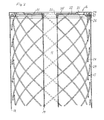
- Figs. 2 shows the steel reinforcement 17 in greater detail.
- a characteristic feature of the reinforcement 17 is the disposition of each of the reinforcing members 28, 29 of the two groups along a spiral line, namely a cylindrical helical line, between the end covers 15 and 16.
- the reinforcing members 28 are disposed along an imaginary cylindrical surface slightly closer to the shell 13 than the reinforcing members 29 of the other group, which are also disposed on an imaginary cylindrical surface and the hand of which is opposite to the hand of the reinforcing members of the first group.
- the two imaginary cylindrical surfaces are concentric with the shell 13 and the centre tube 14.
- the helix angle of all reinforcing members is about 45°, and at least at some of their intersections the reinforcing members suitably are interconnected by wire bindings or other suitable interconnecting members (not shown).
- each reinforcing member 28, 29 suitably is enclosed in a tubular sheath (not shown in the drawings).
- the storage device 40 shown in Fig. 3, which is hereinafter also designated as a cask, is primarily intended for interim or other relatively short-term storage of nuclear fuel, especially during shipping or transfer of nuclear fuel units, e.g. when moving nuclear fuel units from storage pools to a long-term storage site.
- the cask 40 differs from the cask 10 of Figs. 1, 2 in that it only has a single fuel receiver or storage vessel 41, which is centrally positioned and not intended to be completely surrounded by the concrete. Instead, the storage vessel 41 is sealed by means of a separate non-permanent or reopenable closure device 41, which is only diagrammatically shown in Fig. 3 because it may be of any suitable conventional design.
- Fig. 3 also shows a fuel unit B held in a centered position in the storage space defined by the storage vessel 41, resting on a pedestal 43 therein.
- the cask 40 has no separate cooling arrangement. Because the storage is of a short-term nature, the heat produced by the fuel unit can be absorbed by the concrete body without undue heating of the cask. However, if the cask should require separate cooling means, it may be provided with a number of through axial passages which are disposed in a ring about the storage vessel 41 and extend axially through the cask. Air or water can flow upwardly through the passages by natural convection to carry away heat conducted outwardly from the storage vessel 41.
- the outer side of the concrete body 44 is provided with a metal jacket 45 which extends over and past, upwardly and downwardly, the section of the storage vessel 41 that accommodates the nuclear fuel unit B.
- This jacket which is suitably made of steel, has a considerable wall thickness, e.g. 10 cm. It adds to the radiation protection afforded by the section of the concrete body 44 it encloses.
- the diameter of the concrete body 44 can therefore be substantially smaller than in the case where the concrete body alone provides the radiation protection.
- the reinforcement 46 is essentially identical with the reinforcement 17 in Fig. 1. However, the end covers 47 and 48 are slightly different from those shown in Fig. 1. In this case the rail 27 is positioned on the outer side of the outer plate 47A, 48A in an annular groove the bottom wall of which engages the outer side of the inner end cover plate 47B, 48B.
- the design of the end covers shown in Fig. 3 can also be used for the storage container shown in Fig. 1. It is advantageous in that the reinforcing members 46A, 46B are more easily accessible for tensioning and anchoring tha in the design shown in Fig. 1.
- the installation or system shown in Fig. 4 for the manufacture of the sealed storage containers 10 with the nuclear fuel contained therein may suitably be located near the site where the storage containers are to be kept during storage, regardless of whether that site is an ultimate storage site or an interim storage site.
- the storage site may be near a nuclear power plant or at some other place where spent nuclear fuel is stored.
- the nuclear fuel is presumed to be temporarily kept under water in a pool which is dedicated to such short-term storage and from which it is transferred to the system according to the invention.
- this pool is designated by 50 and comprises three individual pool sections.
- the nuclear fuel is transferred in shipping or interim storage containers 51 of the kind shown in Fig. 3, for example, to a different pool or pool system 52 having three pool sections 53, 54, 55 which can be selectively placed in communication with one another, suitably through water locks (only diagrammatically indicated at L in Fig. 4).
- the transfer of the containers 51 is symbolised by arrows A which also symbolises the facilities required for the transfer, such as hoisting or conveying machinery and any other necessary load-handling and control equipment etc.
- Pool section 53 which is dedicated to receiving the interim storage containers 51 coming from the pool 50, is filled with water to a depth which is at least equal to and preferably at least 2-3 m greater than the sum of the height of the transport storage containers 51 and the height of the fuel units held in the containers 51.
- the fuel units B can be lifted from the containers 51 and then shifted horizontally without penetrating the water surface.
- the fuel units should newer come closer to the water surface than 2-3 m.
- the fuel units can be taken out of the interim storage containers by the side of the pool section and put down into racks or other suitable holders in the pool.
- the fuel units removed from the transport containers 51 are introduced into the storage vessels 18 mounted in the formwork which has been prepared for the manufacture of the casks 10 and immersed in the body of water held in the pool section 54.
- the fuel units are taken from the pool section 53 and moved under water to the pool section 54 where they are put down into the storage vessels 18 in the formwork; throughout this operation the fuel units are completely immersed in the water.
- the depth of the body of water in the pool section 54 is at least equal to the height of the formwork and the height of the fuel units, and preferably several metres greater.
- the formwork is assembled in an assembly station 56 by the side of the pool 52 and then lifted and moved to the pool section 54 and placed on the pool bottom. Assembly can be carried out using pre-assembled units which are transported to the assembly station where the formwork is assembled from these units. This is diagrammatically shown in Fig. 4 where the assembly station 56 comprises three sections designated by 57, 58 and 59.
- the lower end cover 15 is assembled and the shell 13 and the centre tube 14 are mounted on the lower end cover.
- the unit 60 so formed is then moved to the section 59 where the group of storage vessels 18 forming the fuel receiver is added to the unit and secured in position therein by means of suitable supporting and anchoring means.
- This step which can also be carried out in the section 57, is symbolised by an arrow C which also symbolises the facilities required for carrying out the step, such as hoisting or conveying machinery and any other necessary load-handling and control equipment etc.
- section 58 of the assembly station 56 the upper end cover 16 and the reinforcement 17 are joined to form a unit 61 which is then lifted and moved to the section 59 and combined with the unit 60 to form the completed formwork 62.
- This step is symbolised by an arrow D which also symbolises the facilities required for carrying out the step, such as hoisting or conveying machinery and any other necessary load-handling and control equipment etc.
- the unit formed by the formwork 62 is then lifted and moved to the pool section 54 and put down on the bottom of that pool section and filled with water. Prior to that, the storage vessels 18 have been filled with the coolant, such as pure water.
- This step is symbolised by an arrow E which also symbolises the facilities required for carrying out the step, such as hoisting or conveying machinery and any other necessary load-handling and control equipment etc.
- the fuel units are transferred from pool section 53 into the storage vessels 18 in the formwork 62 (arrow B). Naturally, the fuel units then displace some of the pure water in the vessels 18. Because of the pre-filling of the storage vessels with the pure water coolant, contamination of the coolant is avoided.
- the depth of the water in pool section 54 of course should be great enough to ensure that the fuel units need not come closer to the water surface than 2 to 3 m.
- the storage vessels 18 are sealed, whereupon the formwork 62 is transferred to the pool section 55.
- the depth of the water body therein in great enough to ensure that the formwork will be completely immersed.
- the depth of the water is such that the top of the formwork is at least 2 to 3 m below the water surface.
- the transfer of the formwork to the pool section is symbolised by an arrow F which also symbolises the facilities required for carrying out the transfer step, such as hoisting or conveying machinery and any other necessary load-handling and control equipment etc.
- the formwork 62 is filled with concrete taken from a nearby concrete station 63.
- the placement of the concrete in the formwork is carried out by means of one or more so-called tremie tubes, that is, placing tubes used for underwater placement of concrete, which are passed through the openings 34, 35 in the upper end cover 16 down to near the lower end cover 15.
- tremie tubes that is, placing tubes used for underwater placement of concrete, which are passed through the openings 34, 35 in the upper end cover 16 down to near the lower end cover 15.
- the placing tube or tubes is/are raised such that the lower tube end is constantly slightly below that surface.
- the concrete may be vibrated during the placement.
- the concrete placement step described in the preceding paragraph is symbolised by an arrow G which also symbolises the facilities required for carrying out the this step, such as hoisting or conveying machinery and any other necessary load-handling and control equipment, the tremie or placing tubes, etc.
- the reinforcement 17 When the concrete has set and hardened to some extent, but not reached its ultimate strength, such as after one or two days, the reinforcement 17 is tensioned to some degree, working from the upper end cover 16. The completed cask 10 can then be taken out of the pool section 55. After some additional time, the reinforcement 17 is further tensioned in one or more steps, until it has reached its final pre-tension. This aftertensioning is suitably carried out from both end covers 15, 16. Containment of the reinforcing members in tubular sheaths, which may be filled with a lubricant, ensures transmission of the tensioning force all the way between the end covers. When the tensioning is completed, concrete may be injected into the sheaths and the cavities at the rails 27 in the end covers.
- the completed cask is transported to a storage site, designated by 64 in Fig. 4.
- the casks 10 may be stacked, e.g. with three casks in each stack, leaving an open space between the stacks so that air, or water if the storage site is in water, can flow freely between the stacks.
- the stacks are suitably placed on a support which allows air or water to flow into and upwardly through the shafts formed by the aligned central passages 11 in the casks 10.
- this shaft may be extended upwardly by means of an extension tube for enhancing the chimney draught or thermosiphon flow that the shaft produces as a result of the heating of the air or water caused by the heat generated by the nuclear fuel in the casks 10 and conducted to the shaft.
- a purifying system 65 Adjacent to the pool section 55 a purifying system 65 is provided, through which the water in that pool section is circulated to be purified.
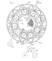
- the manufacturing system or plant shown in Figs. 5 to 7 largely embodies the principles of the system shown in Fig. 4 but is somewhat different in respect of the construction of the pool 52, that is, the part of the system in which the fuel units are introduced into the storage vessels mounted in the formwork and concrete is placed in the formwork.
- Parts in Figs. 5-7 for which there are corresponding parts in Fig. 4 have the same reference numerals as the parts in Fig. 4.
- the pool 52 in Figs. 5-7 differs from the pool in Fig. 4 mainly by being in the shape of a circular, silo-like construction, in which the formvork 62 is moved along an arcuate path.
- the outermost part of the pool 52 is formed by an outer wall 52A, which is a truss-like circular cylindrical shell construction with an outer shell 52B, an inner shell 52C and a number of walls 52C interconnecting the outer and inner shells.
- the open spaces between the outer and inner shells may be used as storage rooms for equipment and materials used in the production of casks.
- a circular cylindrical inner wall 52F Inside the outer wall 52A and concentric with it there is a circular cylindrical inner wall 52F.
- the space between the outer wall 52A and the inner wall 52F, and also the space inside the inner wall are filled with water.
- the last-mentioned space forms the pool section 53 where the shipping storage containers 51 and the fuel units B are placed before the fuel units are transferred to the storage vessels 18 in the formwork 62.
- pool section 54 may be regarded as corresponding to a part of the pool section 54 of Fig. 4, while the pool sections 55A and 55B may be regarded as corresponding respectively to the rest of the pool section 54 and the pool section 55 of Fig. 4. Pool sections 54A and 55C have no direct counterparts in Fig. 4.
- the assembled formwork 62 with the storage vessels 18 mounted therein are transferred, e.g. lifted over to pool section 53 in which they are placed on a carriage 70 that is movable on a track 71.
- This track runs along a circular line or path through all pool sections except pool section 55C and may be slightly inclined in the direction of movement of the carriages 70 to facilitate the movement.
- the formwork 62 may be moved from pool section 554 to the following pool sections 54A, 55A, 55B and 55C. In order that this movement may take place without intermixing the water contained in the various sections too much, the delimitations between pool sections 54A/54B, 54B/55A and 55A/55C are formed by water locks represented by the radial walls shown in the figures.
- the formwork 62 may be moved within and between the pool section by means of hoisting machinery.
- Pool 55C is used in a manner described below to hold casks 10 to be opened for removal of the stored nuclear fuel.
- pool section 54A can hold formwork 62 for two casks at a time, but it may also be dimensioned and designed to hold formwork for either a single cask or more than two casks.
- pool section 55A The thus charged formwork 62 is then moved from pool section 54B to pool section 55A through the intervening water lock.
- pool section 55A the casting of the concrete body of the cask is carried out in the manner described with reference to Fig. 4.
- Pool section 55A can hold formwork 62 for two casks at a time, but it may also be made to hold formwork for a single cask or formwork for more than two casks. If it is made to hold formwork for two or more casks, is may also serve as a buffer space, so that formwork for a cask that has already been cast can be left in pool section 55A until space is free in pool section 55B without the placement of concrete in the formwork for the next cask is obstructed.
- the formwork 62 with the placed concrete therein is moved to pool section 55B where the concrete is allowed to set and harden and supplemental work on the now more or less completed cask 10 may be carried out, such as initial tensioning and/or aftertensioning of the reinforcement members.
- the cask When the concrete in the cask 10 has hardened sufficiently, the cask is lifted from pool section 55B to be moved to a storage site corresponding to the storage site 64 shown in Fig. 4, if required after additional supplemental work on the casks has been carried out by the side of the pool 52.
- Pool section 55C is used if for some reason a cask 10 containing nuclear fuel needs to be reopened for removal or inspection of the nuclear fuel. This may be necessary if the fuel is to be reprocessed or otherwise has to be removed from the cask.
- the cask 10 is immersed in pool section 55C and opened. If the cask is made in accordance with Figs. 1 to 3, the opening is carried out by working off the concrete above the storage vessels, so that the stored fuel units can be lifted and transferred to the central pool section 53 and placed in shipping casks 51 without having in any phase of the process to be raised to the water surface in the pool section or even come close to it.
- the formwork 62 is not provided with storage vessels corresponding to the storage vessels 18 shown in Fig. 1 before the formwork is placed in pool section 54.
- storage vessels in the form of special fuel containers are used, in which the nuclear fuel is loaded while the fuel containers are in a separate pool or pool section or in pool section 53.
- the part which corresponds to the formwork 62 is prepared so that it can receive the fuel containers after it has been placed in the pool section 54.
- that part of the formwork which corresponds to the formwork unit 60 may be provided with suitable guides and supports enabling positioning of the fuel containers correctly in the formwork prior to the placement of the concrete.
- That part of the formwork which corresponds to the formwork unit 60 may first be placed in pool section 54, in which the fuel containers are the positioned in that part, whereupon the part corresponding to the formwork unit 61 is mounted.
Landscapes
- Engineering & Computer Science (AREA)
- High Energy & Nuclear Physics (AREA)
- Physics & Mathematics (AREA)
- General Engineering & Computer Science (AREA)
- Mechanical Engineering (AREA)
- Manufacturing & Machinery (AREA)
- Chemical & Material Sciences (AREA)
- Ceramic Engineering (AREA)
- Environmental & Geological Engineering (AREA)
- Filling Or Discharging Of Gas Storage Vessels (AREA)
- Details Of Rigid Or Semi-Rigid Containers (AREA)
- Conveying And Assembling Of Building Elements In Situ (AREA)
- Solid Fuels And Fuel-Associated Substances (AREA)
- Structure Of Emergency Protection For Nuclear Reactors (AREA)
- Processing Of Solid Wastes (AREA)
- Underground Structures, Protecting, Testing And Restoring Foundations (AREA)
Claims (25)
- Verfahren zur Lagerung von Kernbrennstoff in einem Lagerungsbehälter (10), der einen Betonkörper (12) und eine in dem Betonkörper eingebettete Brennstoffaufnahme (18) umfasst, enthaltend die Schritte- Einführen des Kernbrennstoffs in die Brennstoffaufnahme,- Bereitstellen einer Schalung (62) für den Betonkörper (12) und Anbringen der Brennstoffaufnahme in der Schalung,- Anordnen der Schalung in einer getauchten Position in einem Becken (52), das einen Wasserkörper enthält,- Anordnen von Beton in der getauchten Schalung (62), um den Betonkörper (12) zu bilden, und- Entfernen der Schalung mit dem darin gebildeten Betonkörper aus dem Becken (52).
- Verfahren nach Anspruch 1, bei welchem der Kernbrennstoff in die Brennstoffaufnahme eingeführt wird, nachdem die Schalung (62) in der getauchten Position in dem Becken (54) angeordnet wurde.
- Verfahren nach Anspruch 2, bei welchem der Brennstoff (B) von einer Unterwasserposition in einem benachbarten Becken oder Beckenabschnitt (53) in die Brennstoffaufnahme (18) übertragen wird.
- Verfahren nach Anspruch 2 oder 3, bei welchem anschließend an das Einführen des Kernbrennstoffs (B) in die Brennstoffaufnahme (18) und das Versiegeln der Brennstoffaufnahme die Schalung (62), während sie in einer getauchten Position ist, in ein benachbartes Becken oder einen benachbarten Beckenabschnitt (55) übertragen wird, in dem das Einfüllen des Betons in die Schalung (62) bewirkt wird.
- Verfahren nach Anspruch 3, bei welchem der Kernbrennstoff in dem benachbarten Becken oder Beckenabschnitt (53) platziert wird, während er in einem Transportbehälter (51) untergebracht ist, und bei welchem der Transportbehälter in einer getauchten Position in diesem Becken oder Beckenabschnitt platziert wird.
- Verfahren nach Anspruch 1, bei welchem der Brennstoff in die Brennstoffaufnahme eingeführt wird, bevor die Brennstoffaufnahme in die Schalung eingeführt wird, und bei welchem die Brennstoffaufnahme mit dem darin eingeführten Brennstoff in der Schalung platziert wird, nachdem die Schalung in der getauchten Position in dem Becken (52) platziert wurde.
- Verfahren nach Anspruch 6, bei welchem die Brennstoffaufnahme mit dem darin eingeführten Brennstoff in einer getauchten Position von einem Becken oder Beckenabschnitt, der bzw. das einen Wasserkörper enthält, zu der getauchten Schalung übertragen wird.
- Verfahren nach einem der Ansprüche 1 bis 7, bei welchem die Brennstoffaufnahme (18) in dem Beton fugenlos eingebettet wird.
- Verfahren nach einem der Ansprüche 1 bis 8, bei welchem der Betonkörper (12) in der Form eines im wesentlichen geraden, aufrechtstehenden Zylinders gegossen wird.
- Verfahren nach Anspruch 9, bei welchem der Betonkörper (12) mit einem zentralen, axialen Durchgangskanal (11) geformt wird und die Brennstoffaufnahme (18) in dem Betonkörper als eine Anzahl von einzeln versiegelbaren Aufnahmeabschnitten vorgesehen wird, die um den zentralen Kanal angeordnet sind, und bei welchem der Kernbrennstoff (B) während seines Einführens in die Brennstoffaufnahme auf die Aufnahmeabschnitte verteilt wird.
- Verfahren nach einem der Ansprüche 1 bis 10, bei welchem die Schalung (62) als eine permanente Schalung mindestens aus den folgenden Bestandteilen zusammengesetzt wird: eine untere Endabdeckung (15), eine obere Endabdeckung (16) und eine zylindrische Außenwand (13), die mit den Endabdeckungen verbunden ist, und bei welchem eine Bewehrung (17) in der Schalung (62) montiert und in den Endabdeckungen (15, 16) verankert wird.
- Verfahren nach Anspruch 11, bei welchem die Bewehrung (17) als zwei Gruppen von Bewehrungselementen (28, 29) vorgesehen wird, die schraubenlinienförmig entlang zwei imaginären Zylinderoberflächen innerhalb von und nahe an der Innenseite der äußeren Schalungswand (13) verlaufen, wobei die Bewehrungselemente (28) jeder Gruppe in Umfangsrichtung gleichmäßig beabstandet sind und den gleichen Drehsinn haben, wohingegen der Drehsinn der Bewehrungselemente (28) der anderen Gruppe dem Drehsinn der Bewehrungselemente der ersten Gruppe entgegengesetzt ist.
- Verfahren nach einem der Ansprüche 1 bis 12, bei welchem der Beton in der Schalung (62) durch mindestens ein vertikales Einfüllrohr eingefüllt wird, dessen Mündung dem untersten Teil des Schalungshohlraums benachbart positioniert ist, wenn das Einfüllen beginnt, und mit fortschreitendem Einfüllen angehoben wird, so dass sie konstant geringfügig unterhalb der Oberfläche des eingefüllten Betons ist.
- Verfahren nach einem der Ansprüche 9 bis 13, bei welchem die Bewehrungselemente (28, 29) zumindest in einem gewissen Ausmaß unter Spannung gesetzt werden, nachdem der Beton teilweise, jedoch nicht vollständig ausgehärtet ist.
- Verfahren nach einem der Ansprüche 1 bis 14, bei welchem die Schalung außerhalb des Beckens, in dem der Kernbrennstoff in die Brennstoffaufnahme eingeführt wird, zusammengebaut und mit der Brennstoffaufnahme (18) versehen wird.
- System zur Herstellung eines Lagerbehälters (10) für Kernbrennstoff (B), insbesondere verbrauchten Kernbrennstoff, und zum Einschließen des Brennstoffs in einer Brennstoffaufnahme (18) in einem Betonkörper (12), der einen Teil des Lagerbehälters bildet, welches System enthält- ein Wasserbecken (52) mit einer Tiefe, die mindestens gleich der Höhe des herzustellenden Lagerbehälters (10) ist,- Einrichtungen für den Zusammenbau einer Betonschalung (62) für den Betonkörper (12) des Lagerbehälters (10),- Einrichtungen zum Bewegen der Schalung und der Brennstoffaufnahme zu dem Wasserbecken (52),- Einrichtungen zum Einführen des Kernbrennstoffs in die Brennstoffaufnahme (18),- Einrichtungen zum Einfüllen von Beton in die Schalung (62), während die Schalung in dem Wasserbecken (52) in Wasser getaucht ist, um den Betonkörper in der Schalung zu bilden, und- Einrichtungen zum Entfernen der Schalung (62) und des darin gebildeten Betonkörpers (12) aus dem Wasserbecken (52).
- System nach Anspruch 16, bei welchem das Wasserbecken (52) einen ersten Beckenabschnitt (53) zur Unterbringung von getauchtem Kernbrennstoff (B) und einen zweiten Beckenabschnitt (54, 54A) zur getauchten Unterbringung der Schalung (62) aufweist.
- System nach Anspruch 17, umfassend Einrichtungen zum Einführen von Kernbrennstoff in die Brennstoffaufnahme (18), wobei die Brennstoffaufnahme in der Schalung untergebracht ist, sowie Einrichtungen zum Versiegeln der Brennstoffaufnahme mit dem darin untergebrachten Kernbrennstoff.
- System nach Anspruch 18, bei welchem die Einrichtungen zum Einführen von Kernbrennstoff in die Brennstoffaufnahme (18) Einrichtungen zum Übertragen von Brennstoff von dem ersten Beckenabschnitt (53) zu dem zweiten Beckenabschnitt (54) und zum Einführen des Kernbrennstoffs in die Brennstoffaufnahme (18) in dem zweiten Beckenabschnitt (54) umfassen.
- System nach einem der Ansprüche 17 bis 19, bei welchem das Wasserbecken (52) mehrere Beckenabschnitte (54A, 54B, 55A, 55B, 55C) hat, die entlang einer schleifenförmigen Linie, vorzugsweise einem Kreis, angeordnet sind, und bei welchem das System Ausrüstungen (70, 71) zum Bewegen der Betonschalung (62) zwischen den Beckenabschnitten umfasst.
- System nach einem der Ansprüche 17 bis 20, bei welchem das Wasserbecken einen dritten Beckenabschnitt (55, 55B) zur getauchten Unterbringung der Schalung (62) mit in die Brennstoffaufnahme (18) eingeführtem Kernbrennstoff (B) umfasst.
- System nach einem der Ansprüche 18 bis 21, bei welchem die Beckenabschnitte (53-55) durch Wasserschleusen miteinander verbunden sind.
- System nach einem der Ansprüche 16 bis 21, bei welchem die Einrichtungen zum Zusammenbauen der Schalung (62) zu dem Wasserbecken (52) benachbart angeordnet sind.
- System nach einem der Ansprüche 16 bis 23, bei welchem die Einrichtungen zum Entfernen der Schalung (62) und des darin befindlichen Betonkörpers (12) aus dem Wasserbecken (52) eine Einrichtung zum Transportieren der entfernten Schalung zu einem Lagerplatz (64) für die Lagerbehälter (10) enthalten.
- Verfahren zur Lagerung von Kernbrennstoff, enthaltend die Schritte- Vorsehen einer Vielzahl von gemäß einem der Ansprüche 16 bis 24 hergestellten, im wesentlichen zylindrischen Lagerbehältern (10), die jeweils einen Betonkörper (12) und eine Brennstoffaufnahme (18) enthalten, die den Kernbrennstoff (B) aufnimmt und in dem Betonkörper eingebettet ist, wobei jeder Lagerbehälter einen zentral angeordneten, axial verlaufenden Durchgangskanal (11) hat, der mindestens teilweise durch den Betonkörper (12) gebildet ist und in Wärme übertragender Beziehung mit der Brennstoffaufnahme (18) angeordnet ist, um Wärme von dieser aufzunehmen,- Stapeln der Behälter (10), wobei die zentralen Kanäle der Behälter fluchtend ausgerichtet sind und miteinander in offener Kommunikation stehen, und- Einspeisen eines flüssigen Kühlmittels in das untere Ende des zentralen Kanals des untersten Lagerbehälters und Ausleiten des flüssigen Kühlmittels aus dem oberen Ende des zentralen Kanals des obersten Lagerbehälters.
Applications Claiming Priority (3)
| Application Number | Priority Date | Filing Date | Title |
|---|---|---|---|
| SE0001328A SE516262C2 (sv) | 2000-04-11 | 2000-04-11 | Sätt för framställning av förvaringsbehållare för kärnbränsle och anläggning för utförande av sättet |
| SE0001328 | 2000-04-11 | ||
| PCT/SE2001/000811 WO2001078084A1 (en) | 2000-04-11 | 2001-04-11 | Method and system for manufacturing storage container for storing nuclear fuel |
Publications (2)
| Publication Number | Publication Date |
|---|---|
| EP1273012A1 EP1273012A1 (de) | 2003-01-08 |
| EP1273012B1 true EP1273012B1 (de) | 2007-03-14 |
Family
ID=20279265
Family Applications (1)
| Application Number | Title | Priority Date | Filing Date |
|---|---|---|---|
| EP01920093A Expired - Lifetime EP1273012B1 (de) | 2000-04-11 | 2001-04-11 | Verfahren und system zur herstellung eines speicherbehälters zum lagern von kernbrennstoff |
Country Status (11)
| Country | Link |
|---|---|
| US (3) | US6785355B2 (de) |
| EP (1) | EP1273012B1 (de) |
| JP (1) | JP2003530578A (de) |
| KR (1) | KR20020092429A (de) |
| AT (1) | ATE357047T1 (de) |
| AU (1) | AU2001247036A1 (de) |
| DE (1) | DE60127245T2 (de) |
| RU (1) | RU2264669C2 (de) |
| SE (1) | SE516262C2 (de) |
| UA (1) | UA76414C2 (de) |
| WO (1) | WO2001078084A1 (de) |
Cited By (1)
| Publication number | Priority date | Publication date | Assignee | Title |
|---|---|---|---|---|
| CN104364850A (zh) * | 2012-06-15 | 2015-02-18 | Tn国际公司 | 用于将放射性元件装载到封装件中的优化方法 |
Families Citing this family (17)
| Publication number | Priority date | Publication date | Assignee | Title |
|---|---|---|---|---|
| SE520672C2 (sv) * | 2001-12-18 | 2003-08-12 | Oyster Internat Nv C O H B Man | Elektrokrom anordning baserad på nanokristallina material |
| SE525468C2 (sv) * | 2002-11-29 | 2005-03-01 | Oyster Internat Nv C O H B Man | Behållaranordning för förvaring av riskmaterial, i synnerhet för slutförvaring av kärnbränsle, och sätt för dess framställning |
| SE526935C2 (sv) * | 2003-12-30 | 2005-11-22 | Oyster Internat Nv C O H B Man | Behållaranordning för förvaring av riskmaterial, i synnerhet för slutförvaring av kärnbränsle, och sätt för dess framställning |
| US8098790B2 (en) * | 2004-03-18 | 2012-01-17 | Holtec International, Inc. | Systems and methods for storing spent nuclear fuel |
| US20070034541A1 (en) * | 2005-02-17 | 2007-02-15 | Board Of Regents Of The University And College System Of Nevada | Nuclear material container and methods of use |
| WO2006135987A1 (en) * | 2005-06-24 | 2006-12-28 | Australian Nuclear Science And Technology Organisation | Method and apparatus for isolating material from its processing environment |
| EP2214847B1 (de) | 2007-11-08 | 2018-08-08 | P&T Global Solutions, LLC | System und verfahren zum befüllen eines behälters mit gefährlichen abfällen |
| FR2952468B1 (fr) * | 2009-11-10 | 2012-01-13 | Tn Int | Emballage pour le transport et/ou entreposage de matieres radioactives comprenant des elements de protection radiologique empiles radialement |
| CA2858381C (en) * | 2011-12-08 | 2020-03-24 | Atomic Energy Of Canada Limited/Energie Atomique Du Canada Limitee | Apparatus for holding radioactive objects |
| FR2988898A1 (fr) * | 2012-03-28 | 2013-10-04 | Commissariat Energie Atomique | Procede et dispositif mobile permettant de reduire les resistances thermiques entre deux solides |
| US9406409B2 (en) * | 2013-03-06 | 2016-08-02 | Nuscale Power, Llc | Managing nuclear reactor spent fuel rods |
| CN104453234B (zh) * | 2013-09-17 | 2018-10-16 | 中广核工程有限公司 | 带变截面超大环形结构的施工方法及使用的自密实混凝土 |
| US10633163B1 (en) * | 2018-01-24 | 2020-04-28 | William M. Arnold | Transport container for radioactive material |
| CN110993136B (zh) * | 2019-12-30 | 2025-04-11 | 中核武汉核电运行技术股份有限公司 | 一种燃料组件上管座套筒螺钉水下存储容器 |
| US11881323B2 (en) | 2020-11-25 | 2024-01-23 | Holtec International | High-density subterranean storage system for nuclear fuel and radioactive waste |
| EP4252258A4 (de) * | 2020-11-25 | 2024-10-16 | Holtec International | Unterirdisches lagersystem hoher dichte für kernbrennstoff und radioaktiven abfall |
| KR102870619B1 (ko) * | 2025-04-15 | 2025-10-16 | 태산엔지니어링 주식회사 | 사용후 핵 연료봉 집합체의 이동 및 저장 장치, 그리고 이를 이용한 사용후 핵 연료봉 집합체의 저장 방법 |
Family Cites Families (37)
| Publication number | Priority date | Publication date | Assignee | Title |
|---|---|---|---|---|
| SE338949B (de) * | 1961-12-21 | 1971-09-20 | H Georgil | |
| DE1684643C2 (de) * | 1968-01-16 | 1975-11-27 | Dyckerhoff & Widmann Ag, 8000 Muenchen | Spannbeton-Druckbehalter mit Rmgspanngliedern, die durch Aufweiten der gebildeten Ringe gespannt sind |
| SE354630B (de) * | 1968-05-17 | 1973-03-19 | Hydro Betong Ab | |
| GB1287000A (en) * | 1968-12-20 | 1972-08-31 | Hans Christer Georgii | Apparatus for the manufacture of floating concrete structures in a body of water |
| US3883012A (en) * | 1971-10-21 | 1975-05-13 | Transfer Systems | Dry cask handling system for shipping nuclear fuel |
| US3825220A (en) * | 1972-11-07 | 1974-07-23 | E Schmaltz | Concrete form work joint members |
| US3913335A (en) * | 1973-07-25 | 1975-10-21 | Sigurd Heien | Offshore terminal |
| SE386258B (sv) * | 1974-04-08 | 1976-08-02 | H Georgii | Forfarande och anordning for utvinnande av geotermisk energi fran en aktiv undervattensvulkan |
| US4069923A (en) * | 1974-12-16 | 1978-01-24 | Ebasco Services Incorporated | Buoyancy elevator for moving a load in an industrial facility such as a nuclear power plant |
| US4011728A (en) * | 1975-01-17 | 1977-03-15 | Turzillo Lee A | Means for producing subaqueous and other cast-in-place concrete structures in situ |
| US4257912A (en) * | 1978-06-12 | 1981-03-24 | Westinghouse Electric Corp. | Concrete encapsulation for spent nuclear fuel storage |
| NO144361C (no) * | 1979-05-30 | 1981-08-12 | Selmer As Ing F | Fremgangsmaate og anlegg for utfoerelse av glidestoeping av betongkonstruksjoner under vann |
| JPS5639235A (en) * | 1979-09-03 | 1981-04-14 | Nippon Sheet Glass Co Ltd | Construction method for underwater concrete structure |
| HU179174B (en) * | 1979-09-14 | 1982-08-28 | Eroemue Es Halozattervezoe | Process and apparatus for transferring and housing radioactive and/or other dangerous materials |
| FR2484685A1 (fr) * | 1980-06-13 | 1981-12-18 | Commissariat Energie Atomique | Installation de stockage d'assemblages combustibles irradies |
| US4377509A (en) * | 1980-07-14 | 1983-03-22 | The United States Of America As Represented By The Secretary Of The Navy | Packaging for ocean disposal of low-level radioactive waste material |
| DE3301735C2 (de) * | 1983-01-20 | 1986-04-10 | Kernforschungsanlage Jülich GmbH, 5170 Jülich | Übergangslager für hochradioaktiven Abfall |
| DE3515871A1 (de) | 1985-05-03 | 1986-11-06 | Hochtemperatur-Reaktorbau GmbH, 4600 Dortmund | Transport- und lagerbehaelter fuer brennelemente |
| US4800062A (en) * | 1987-02-23 | 1989-01-24 | Nuclear Packaging, Inc. | On-site concrete cask storage system for spent nuclear fuel |
| US5024557A (en) * | 1987-09-22 | 1991-06-18 | Iorns Martin E | Method and apparatus for constructing an offshore hollow column |
| US5008045A (en) * | 1989-03-23 | 1991-04-16 | Alternative Technologies For Waste, Inc. | Method and apparatus for centrifugally casting hazardous waste |
| US5043103A (en) * | 1989-03-23 | 1991-08-27 | Manchak Frank | Method and apparatus for centrifugally casting hazardous waste |
| IT1235121B (it) * | 1989-07-13 | 1992-06-18 | Casagrande Spa | Sistema per lo stoccaggio permanente dei rifiuti radioattivi. |
| WO1991005351A1 (en) * | 1989-10-09 | 1991-04-18 | Hydro Betong Ab | An arrangement for the storage of environmentally hazardous waste |
| JPH0675854B2 (ja) * | 1989-12-14 | 1994-09-28 | 株式会社フジタ | 水分含有率の高いコンクリートの製造方法 |
| US5291532A (en) * | 1992-02-14 | 1994-03-01 | General Electric Company | Fuel transfer system |
| US5545796A (en) * | 1994-02-25 | 1996-08-13 | Scientific Ecology Group | Article made out of radioactive or hazardous waste and a method of making the same |
| US5646971A (en) * | 1994-11-16 | 1997-07-08 | Hi-Temp Containers Inc. | Method and apparatus for the underwater loading of nuclear materials into concrete containers employing heat removal systems |
| SE509491C2 (sv) * | 1995-01-10 | 1999-02-01 | Hydro Betong Ab | Sätt och anordning för lagring av riskavfall |
| SE504793C2 (sv) * | 1995-05-15 | 1997-04-28 | Hydro Betong Ab | Anläggning för offshore-förvaring av riskavfall samt baskropp med förvaringsutrymmen |
| US5599139A (en) * | 1995-06-07 | 1997-02-04 | The Tensar Corporation | Method of constructing a liner system and waste containment facility incorporating same |
| RU2095865C1 (ru) * | 1995-06-14 | 1997-11-10 | Конструкторское бюро специального машиностроения | Способ изготовления контейнера для транспортировки и/или хранения отработавшего ядерного топлива |
| RU2088984C1 (ru) * | 1995-07-26 | 1997-08-27 | Конструкторское бюро специального машиностроения | Способ изготовления контейнера для транспортировки и/или хранения отработавшего ядерного топлива |
| US5819186A (en) * | 1996-04-26 | 1998-10-06 | Stephens; Patrick J. | Cellular grout radiation barrier |
| SE506569C2 (sv) * | 1996-05-10 | 1998-01-12 | Asea Atom Ab | Metod och anordning vid rörelsekorrektion och positionering av en upphängningsanordning |
| ATE227880T1 (de) * | 1999-12-15 | 2002-11-15 | Gnb Gmbh | Verfahren zum herstellen eines transport- und/oder lagerbehälters für radioaktive gegenstände |
| KR100383409B1 (ko) * | 2000-04-19 | 2003-05-14 | (주)평화엔지니어링 | 강재 가물막이를 이용한 직접기초 시공방법 |
-
2000
- 2000-04-11 SE SE0001328A patent/SE516262C2/sv not_active IP Right Cessation
-
2001
- 2001-04-11 US US10/257,141 patent/US6785355B2/en not_active Expired - Fee Related
- 2001-04-11 DE DE60127245T patent/DE60127245T2/de not_active Expired - Fee Related
- 2001-04-11 AT AT01920093T patent/ATE357047T1/de not_active IP Right Cessation
- 2001-04-11 WO PCT/SE2001/000811 patent/WO2001078084A1/en not_active Ceased
- 2001-04-11 JP JP2001575442A patent/JP2003530578A/ja active Pending
- 2001-04-11 EP EP01920093A patent/EP1273012B1/de not_active Expired - Lifetime
- 2001-04-11 KR KR1020027013707A patent/KR20020092429A/ko not_active Ceased
- 2001-04-11 AU AU2001247036A patent/AU2001247036A1/en not_active Abandoned
- 2001-04-11 RU RU2002129888/06A patent/RU2264669C2/ru not_active IP Right Cessation
- 2001-11-04 UA UA2002097238A patent/UA76414C2/uk unknown
-
2004
- 2004-08-02 US US10/902,842 patent/US20050201506A1/en not_active Abandoned
-
2005
- 2005-11-14 US US11/272,015 patent/US20060120500A1/en not_active Abandoned
Cited By (2)
| Publication number | Priority date | Publication date | Assignee | Title |
|---|---|---|---|---|
| CN104364850A (zh) * | 2012-06-15 | 2015-02-18 | Tn国际公司 | 用于将放射性元件装载到封装件中的优化方法 |
| CN104364850B (zh) * | 2012-06-15 | 2018-05-08 | Tn国际公司 | 用于将放射性元件装载到封装件中的优化方法 |
Also Published As
| Publication number | Publication date |
|---|---|
| US20050201506A1 (en) | 2005-09-15 |
| JP2003530578A (ja) | 2003-10-14 |
| DE60127245T2 (de) | 2008-04-03 |
| US20060120500A1 (en) | 2006-06-08 |
| AU2001247036A1 (en) | 2001-10-23 |
| WO2001078084A1 (en) | 2001-10-18 |
| RU2264669C2 (ru) | 2005-11-20 |
| US6785355B2 (en) | 2004-08-31 |
| UA76414C2 (en) | 2006-08-15 |
| SE516262C2 (sv) | 2001-12-10 |
| DE60127245D1 (de) | 2007-04-26 |
| KR20020092429A (ko) | 2002-12-11 |
| SE0001328D0 (sv) | 2000-04-11 |
| ATE357047T1 (de) | 2007-04-15 |
| SE0001328L (sv) | 2001-10-12 |
| US20030167735A1 (en) | 2003-09-11 |
| EP1273012A1 (de) | 2003-01-08 |
Similar Documents
| Publication | Publication Date | Title |
|---|---|---|
| EP1273012B1 (de) | Verfahren und system zur herstellung eines speicherbehälters zum lagern von kernbrennstoff | |
| EP0871963B1 (de) | Verfahren und vorrichtung zum lagern von gefährlichem abfall | |
| US6958483B2 (en) | Container device for the storage of hazardous materials and a method of making it | |
| JP2004519664A (ja) | 熱発生材料を貯蔵するための装置およびそのような装置のための容器 | |
| EP1565917B1 (de) | Behältereinrichtung zum lagern von gefährlichen materialien insbesondere für die endlagerung von kernbrennstoff und verfahren zu ihrer herstellung | |
| EP1273011B1 (de) | Einrichtung zur lagerung von gefährlichem material | |
| US6696695B1 (en) | Storage container for hazardous material | |
| US20030138070A1 (en) | Device for storage of hazardous material | |
| JPH1082893A (ja) | 放射性廃棄物処分施設及び該施設を用いた放射性廃棄物の地層処分方法 |
Legal Events
| Date | Code | Title | Description |
|---|---|---|---|
| PUAI | Public reference made under article 153(3) epc to a published international application that has entered the european phase |
Free format text: ORIGINAL CODE: 0009012 |
|
| 17P | Request for examination filed |
Effective date: 20020828 |
|
| AK | Designated contracting states |
Kind code of ref document: A1 Designated state(s): AT BE CH CY DE DK ES FI FR GB GR IE IT LI LU MC NL PT SE TR |
|
| AX | Request for extension of the european patent |
Free format text: AL;LT;LV;MK;RO;SI |
|
| GRAP | Despatch of communication of intention to grant a patent |
Free format text: ORIGINAL CODE: EPIDOSNIGR1 |
|
| GRAS | Grant fee paid |
Free format text: ORIGINAL CODE: EPIDOSNIGR3 |
|
| GRAA | (expected) grant |
Free format text: ORIGINAL CODE: 0009210 |
|
| AK | Designated contracting states |
Kind code of ref document: B1 Designated state(s): AT BE CH CY DE DK ES FI FR GB GR IE IT LI LU MC NL PT SE TR |
|
| PG25 | Lapsed in a contracting state [announced via postgrant information from national office to epo] |
Ref country code: CH Free format text: LAPSE BECAUSE OF FAILURE TO SUBMIT A TRANSLATION OF THE DESCRIPTION OR TO PAY THE FEE WITHIN THE PRESCRIBED TIME-LIMIT Effective date: 20070314 Ref country code: NL Free format text: LAPSE BECAUSE OF FAILURE TO SUBMIT A TRANSLATION OF THE DESCRIPTION OR TO PAY THE FEE WITHIN THE PRESCRIBED TIME-LIMIT Effective date: 20070314 Ref country code: LI Free format text: LAPSE BECAUSE OF FAILURE TO SUBMIT A TRANSLATION OF THE DESCRIPTION OR TO PAY THE FEE WITHIN THE PRESCRIBED TIME-LIMIT Effective date: 20070314 Ref country code: AT Free format text: LAPSE BECAUSE OF FAILURE TO SUBMIT A TRANSLATION OF THE DESCRIPTION OR TO PAY THE FEE WITHIN THE PRESCRIBED TIME-LIMIT Effective date: 20070314 Ref country code: BE Free format text: LAPSE BECAUSE OF FAILURE TO SUBMIT A TRANSLATION OF THE DESCRIPTION OR TO PAY THE FEE WITHIN THE PRESCRIBED TIME-LIMIT Effective date: 20070314 |
|
| REG | Reference to a national code |
Ref country code: GB Ref legal event code: FG4D |
|
| REG | Reference to a national code |
Ref country code: CH Ref legal event code: EP |
|
| REF | Corresponds to: |
Ref document number: 60127245 Country of ref document: DE Date of ref document: 20070426 Kind code of ref document: P |
|
| REG | Reference to a national code |
Ref country code: IE Ref legal event code: FG4D |
|
| PG25 | Lapsed in a contracting state [announced via postgrant information from national office to epo] |
Ref country code: SE Free format text: LAPSE BECAUSE OF FAILURE TO SUBMIT A TRANSLATION OF THE DESCRIPTION OR TO PAY THE FEE WITHIN THE PRESCRIBED TIME-LIMIT Effective date: 20070614 |
|
| PG25 | Lapsed in a contracting state [announced via postgrant information from national office to epo] |
Ref country code: ES Free format text: LAPSE BECAUSE OF FAILURE TO SUBMIT A TRANSLATION OF THE DESCRIPTION OR TO PAY THE FEE WITHIN THE PRESCRIBED TIME-LIMIT Effective date: 20070625 |
|
| PG25 | Lapsed in a contracting state [announced via postgrant information from national office to epo] |
Ref country code: PT Free format text: LAPSE BECAUSE OF FAILURE TO SUBMIT A TRANSLATION OF THE DESCRIPTION OR TO PAY THE FEE WITHIN THE PRESCRIBED TIME-LIMIT Effective date: 20070814 |
|
| NLV1 | Nl: lapsed or annulled due to failure to fulfill the requirements of art. 29p and 29m of the patents act | ||
| REG | Reference to a national code |
Ref country code: CH Ref legal event code: PL |
|
| EN | Fr: translation not filed | ||
| EN | Fr: translation not filed | ||
| PLBE | No opposition filed within time limit |
Free format text: ORIGINAL CODE: 0009261 |
|
| STAA | Information on the status of an ep patent application or granted ep patent |
Free format text: STATUS: NO OPPOSITION FILED WITHIN TIME LIMIT |
|
| PG25 | Lapsed in a contracting state [announced via postgrant information from national office to epo] |
Ref country code: DK Free format text: LAPSE BECAUSE OF FAILURE TO SUBMIT A TRANSLATION OF THE DESCRIPTION OR TO PAY THE FEE WITHIN THE PRESCRIBED TIME-LIMIT Effective date: 20070314 |
|
| 26N | No opposition filed |
Effective date: 20071217 |
|
| GBPC | Gb: european patent ceased through non-payment of renewal fee |
Effective date: 20070614 |
|
| PG25 | Lapsed in a contracting state [announced via postgrant information from national office to epo] |
Ref country code: FR Free format text: LAPSE BECAUSE OF FAILURE TO SUBMIT A TRANSLATION OF THE DESCRIPTION OR TO PAY THE FEE WITHIN THE PRESCRIBED TIME-LIMIT Effective date: 20071102 Ref country code: IT Free format text: LAPSE BECAUSE OF FAILURE TO SUBMIT A TRANSLATION OF THE DESCRIPTION OR TO PAY THE FEE WITHIN THE PRESCRIBED TIME-LIMIT Effective date: 20070314 Ref country code: GR Free format text: LAPSE BECAUSE OF FAILURE TO SUBMIT A TRANSLATION OF THE DESCRIPTION OR TO PAY THE FEE WITHIN THE PRESCRIBED TIME-LIMIT Effective date: 20070615 |
|
| PG25 | Lapsed in a contracting state [announced via postgrant information from national office to epo] |
Ref country code: IE Free format text: LAPSE BECAUSE OF NON-PAYMENT OF DUE FEES Effective date: 20070411 Ref country code: GB Free format text: LAPSE BECAUSE OF NON-PAYMENT OF DUE FEES Effective date: 20070614 |
|
| PGFP | Annual fee paid to national office [announced via postgrant information from national office to epo] |
Ref country code: FI Payment date: 20080418 Year of fee payment: 8 |
|
| PG25 | Lapsed in a contracting state [announced via postgrant information from national office to epo] |
Ref country code: FR Free format text: LAPSE BECAUSE OF FAILURE TO SUBMIT A TRANSLATION OF THE DESCRIPTION OR TO PAY THE FEE WITHIN THE PRESCRIBED TIME-LIMIT Effective date: 20070314 |
|
| PG25 | Lapsed in a contracting state [announced via postgrant information from national office to epo] |
Ref country code: MC Free format text: LAPSE BECAUSE OF NON-PAYMENT OF DUE FEES Effective date: 20070430 |
|
| PG25 | Lapsed in a contracting state [announced via postgrant information from national office to epo] |
Ref country code: CY Free format text: LAPSE BECAUSE OF FAILURE TO SUBMIT A TRANSLATION OF THE DESCRIPTION OR TO PAY THE FEE WITHIN THE PRESCRIBED TIME-LIMIT Effective date: 20070314 |
|
| PG25 | Lapsed in a contracting state [announced via postgrant information from national office to epo] |
Ref country code: LU Free format text: LAPSE BECAUSE OF NON-PAYMENT OF DUE FEES Effective date: 20070411 |
|
| PGFP | Annual fee paid to national office [announced via postgrant information from national office to epo] |
Ref country code: DE Payment date: 20090429 Year of fee payment: 9 |
|
| PG25 | Lapsed in a contracting state [announced via postgrant information from national office to epo] |
Ref country code: TR Free format text: LAPSE BECAUSE OF FAILURE TO SUBMIT A TRANSLATION OF THE DESCRIPTION OR TO PAY THE FEE WITHIN THE PRESCRIBED TIME-LIMIT Effective date: 20070314 |
|
| PG25 | Lapsed in a contracting state [announced via postgrant information from national office to epo] |
Ref country code: FI Free format text: LAPSE BECAUSE OF NON-PAYMENT OF DUE FEES Effective date: 20090411 |
|
| PG25 | Lapsed in a contracting state [announced via postgrant information from national office to epo] |
Ref country code: DE Free format text: LAPSE BECAUSE OF NON-PAYMENT OF DUE FEES Effective date: 20101103 |