EP1273065B9 - Procede de fabrication d'une pile a combustible a oxyde solide - Google Patents
Procede de fabrication d'une pile a combustible a oxyde solide Download PDFInfo
- Publication number
- EP1273065B9 EP1273065B9 EP01913733A EP01913733A EP1273065B9 EP 1273065 B9 EP1273065 B9 EP 1273065B9 EP 01913733 A EP01913733 A EP 01913733A EP 01913733 A EP01913733 A EP 01913733A EP 1273065 B9 EP1273065 B9 EP 1273065B9
- Authority
- EP
- European Patent Office
- Prior art keywords
- columns
- solid oxide
- ysz
- anode
- fuel cell
- Prior art date
- Legal status (The legal status is an assumption and is not a legal conclusion. Google has not performed a legal analysis and makes no representation as to the accuracy of the status listed.)
- Expired - Lifetime
Links
Images

Classifications
-
- H—ELECTRICITY
- H01—ELECTRIC ELEMENTS
- H01M—PROCESSES OR MEANS, e.g. BATTERIES, FOR THE DIRECT CONVERSION OF CHEMICAL ENERGY INTO ELECTRICAL ENERGY
- H01M8/00—Fuel cells; Manufacture thereof
- H01M8/10—Fuel cells with solid electrolytes
- H01M8/12—Fuel cells with solid electrolytes operating at high temperature, e.g. with stabilised ZrO2 electrolyte
- H01M8/1213—Fuel cells with solid electrolytes operating at high temperature, e.g. with stabilised ZrO2 electrolyte characterised by the electrode/electrolyte combination or the supporting material
-
- H—ELECTRICITY
- H01—ELECTRIC ELEMENTS
- H01M—PROCESSES OR MEANS, e.g. BATTERIES, FOR THE DIRECT CONVERSION OF CHEMICAL ENERGY INTO ELECTRICAL ENERGY
- H01M8/00—Fuel cells; Manufacture thereof
- H01M8/10—Fuel cells with solid electrolytes
- H01M8/12—Fuel cells with solid electrolytes operating at high temperature, e.g. with stabilised ZrO2 electrolyte
- H01M8/1231—Fuel cells with solid electrolytes operating at high temperature, e.g. with stabilised ZrO2 electrolyte with both reactants being gaseous or vaporised
-
- Y—GENERAL TAGGING OF NEW TECHNOLOGICAL DEVELOPMENTS; GENERAL TAGGING OF CROSS-SECTIONAL TECHNOLOGIES SPANNING OVER SEVERAL SECTIONS OF THE IPC; TECHNICAL SUBJECTS COVERED BY FORMER USPC CROSS-REFERENCE ART COLLECTIONS [XRACs] AND DIGESTS
- Y02—TECHNOLOGIES OR APPLICATIONS FOR MITIGATION OR ADAPTATION AGAINST CLIMATE CHANGE
- Y02E—REDUCTION OF GREENHOUSE GAS [GHG] EMISSIONS, RELATED TO ENERGY GENERATION, TRANSMISSION OR DISTRIBUTION
- Y02E60/00—Enabling technologies; Technologies with a potential or indirect contribution to GHG emissions mitigation
- Y02E60/30—Hydrogen technology
- Y02E60/50—Fuel cells
-
- Y—GENERAL TAGGING OF NEW TECHNOLOGICAL DEVELOPMENTS; GENERAL TAGGING OF CROSS-SECTIONAL TECHNOLOGIES SPANNING OVER SEVERAL SECTIONS OF THE IPC; TECHNICAL SUBJECTS COVERED BY FORMER USPC CROSS-REFERENCE ART COLLECTIONS [XRACs] AND DIGESTS
- Y02—TECHNOLOGIES OR APPLICATIONS FOR MITIGATION OR ADAPTATION AGAINST CLIMATE CHANGE
- Y02P—CLIMATE CHANGE MITIGATION TECHNOLOGIES IN THE PRODUCTION OR PROCESSING OF GOODS
- Y02P70/00—Climate change mitigation technologies in the production process for final industrial or consumer products
- Y02P70/50—Manufacturing or production processes characterised by the final manufactured product
Definitions
- the invention relates to a solid oxide fuel cell for oxidizing gases, such as methane, coal gas or hydrogen, and comprising a solid oxide electrolyte, which is preferably formed by YSZ, and where a thin layer of anode material is attached to the electrolyte, and where a fluid flow-controlling coupling layer is arranged on both the anode and the cathode side.
- gases such as methane, coal gas or hydrogen
- a solid oxide fuel cell which comprises a solid oxide electrolyte, a solid oxide cathode and a cermet anode.
- the operating temperature of a stack of solid oxide cells is approximately 1000°C.
- the electrolyte comprises a Y 2 O 3 -ZrO 2 mixed oxide, a so-called yttrium oxide-stabilized zirconium oxide (YSZ).
- the cathode comprises LaMnO 3 doped with Sr, Mg or Ca.
- the anode comprises a mixture of fine Ni-particles and YSZ.
- the nickel-YSZ-oxide cermet anode is for instance produced by mixing NiO with YSZ (Zr 1x Y x O 2-x/2 ).
- This oxide mixture is sintered on the electrolyte.
- fuel gas is fed in form of H 2 or CH 4 to the cermet anode, NiO is reduced to Ni.
- a cermet anode must be porous in such a manner that the fuel gas can penetrate and react with the O - -ions from the YSZ electrolyte while simultaneously releasing electrons to the nickel metal.
- the anode reaction can only take place in a transition area between the three phases YSZ, Ni and fuel gas.
- the anode reaction is as follows: CH 4 (gas + O - (YSZ)-electrolyte) ⁇ CO 2 (gas)+8e - (in the Ni-metal).
- Ni-phase In order to allow the electrons to be diverted, a passage or a percolation path must exist through the Ni-phase, and for this purpose the % by volume of Ni must exceed 35%.
- CeO 2 based anodes implies that a reduction by means of H 2 or CH 4 results in substoichiometric CeO 2-x , which can conduct both electrons and oxygen ions.
- Such anode allows the oxidation of H 2 or CH 4 to be carried out across the entire surface, viz. the gas bordering surface, e - and O - simultaneously being accessible across the entire surface. The latter is of importance in connection with oxidation of CH 4 , which is the main component in natural gas.
- a coupling layer in form of end plates with channels for the supply of gas flows is arranged on both the anode and the cathode side.
- These end plates involve a relatively cost-intensive manufacture because they must be made of a relatively expensive ceramic material, and furthermore they require relatively much material. In addition, they take up relatively much room and increase the height of a stack of cells to an unnecessary extent.
- WO 92/091116 illustrates a solid oxide fuel cell with an interconnect comprising columns of ceramic material. These columns may be produced without a waste of material. However, the columns are produced in connection with a base of the same ceramic material, and such a base requires additional ceramic material. During the sintering, the stacked, assembled elements may shrink which may result in contact problems.
- the object of the invention is to provide a solid oxide fuel cell which is less expensive to produce than hitherto known, and which in addition presents a higher power density than hitherto known.
- a solid oxide fuel cell of the above type is according to the invention characterised in that the fluid-controlling coupling layer is formed by a number of preferably mutually separated columns.
- the invention relates to a method of manufacturing a solid oxide fuel cell for oxidizing gases according to claim 1.
- a particularly simple method is obtained for the manufacture of a solid oxide fuel cell.
- This method provides furthermore several degrees of freedom with respect to choice of material, which is an essential factor in connection with the mechanical stresses that the materials are subjected to at the operating temperatures in question.
- Fig. 1 illustrates a known solid oxide fuel cell comprising an anode in form of a layer of Ni-YSZ-cermet, a layer of a YSZ-electrolyte 2 and a cathode 3 in form of a layer of La(Sr)MnO 3 .
- the thickness of both the electrodes and the electrolyte is typically 100 ⁇ m. Considerable variation possibilities do, however, apply, from a few ⁇ m and up to 0.3 mm for the electrolyte and up to 1 mm for the electrodes.
- An Ni-YSZ-anode is not particularly suited for oxidation of CH 4 , and it has therefore been replaced by a CeO 2 -based anode 4.
- One measure of preventing CeO 2 from diffusing into YSZ is to add NiO or another transition metallic oxide or auxiliary oxide surfactive on YSZ to CeO 2 .
- Another measure is to paint a layer of such a metallic oxide powder suspended in a dispersant on the YSZ electrolyte 2, whereafter the CeO 2 powder is applied.
- the expression surfactive is to be construed such that the auxiliary oxide, such as MnO 2 or NiO, is easy to distribute uniformly across the YSZ surface, and that the following heat treatment does not cause said auxiliary oxide to get lumpy on the surface.
- the measure can optionally be carried out by mixing up to 30 % by weight of NiO into the CeO 2 -based ceramic powder.
- NiO Ni-doped indium
- Other possible auxiliary oxides are oxides of the transition metals V, Cr, Mn, Fe, Co, Ni, Cu, Zn, Nb, Ta and of Ga, Ge, In, Sn, Sb, Pb and Bi.
- auxiliary oxide The effect of the auxiliary oxide is that the YSZ surface is completely covered by said auxiliary oxide and thereby prevents CeO 2 from diffusing into YSZ, and furthermore that said auxiliary oxide almost glues YSZ and CeO 2 together in connection with a low interfacial tension between said YSZ and CeO 2 .
- the auxiliary oxide layer serving as glue layer must be penetrable to oxygen ions when the fuel cell operates.
- NiO as auxiliary oxide has the effect that during the starting procedure NiO is likely to be reduced to metallic Ni at the interaction of hydrogen.
- Ni resulting from the reduction of NiO appears on the CeO 2 surface as particles of a diameter of approximately 1 ⁇ m or more, problems are likely to arise in connection with the oxidation of CH 4 , Ni being a well-known cracking catalyst. Ni exposed to CH 4 at 1000°C is therefore assumed to cause a liberation of coal, which gradually destroys the anode. In order to avoid the latter, it is possible to ensure that no Ni on the whole is visible on the CeO 2 surface, for instance by NiO only being applied as a layer on the YSZ electrolyte and not mixed with CeO 2 . Such a procedure can for instance also be obtained by allowing the Ni-metal to be exposed to CH 4 at the surface and by treating said surface with H 2 S in return at the start.
- Ni-YSZ cermet electrode Compared to an Ni-YSZ cermet electrode, an Ni-CeO 2-x electrode treated with H 2 S tolerates a possible sulphur content in CH 4 .
- An essential problem associated with the classic Ni-YSZ cermet is that it is inactivated if it is exposed to a sulphur content in the fuel gas of the magnitude 100 ppm for a prolonged period of time.
- Ni-free CeO 2 -based electrodes are also assumed to tolerate sulphur.
- CeO 2 based electrodes 4 A particular problem associated with CeO 2 based electrodes 4 is that such CeO 2-x electrodes are often damaged because some of the O - -ions are removed from the CeO 2-x crystal lattice while some of the Ce +4 -ions are reduced to Ce +3 . As a result the crystal lattice expands both because less negative O"-ions are present to keep the positive Ce-iom together and because a Ce +3 -ion is larger than a Ce +4 -ion. Apparently, a solution of the latter can be found as well.
- the substances dopable to CeO 2 in order to improve the conductivity of the electrons are for instance Nb 2 O 5 , Ta 2 O 5 , TiO 2 , P 2 O 5 , As 2 O 5 , Sb 2 O 5 , Bi 2 O 3 SnO, In 2 0 3 and SO 3 or mixtures thereof or substances resulting in the same mixture by an addition of CeO 2 followed by a heat treatment, such as the carbonates of the same metals or for instance Ce(SO 4 ) 2 in stead of SO 3 or CePO 3 in stead of P 2 O 5 .
- the substances dopable to CeO 2 in order to improve the stability of the volume by way of reduction are metallic oxides, where the metallic ion is mono, di or trivalent, such as Na 2 O. K 2 O, MgO, CaO, SrO, BaO, Sc 2 O 3 , Y 2 O 3 , La 2 O 3 , In 2 O 3 , Ga 2 O 3 as well as tri and divalent lanthanides, Ti 2 O 3 , ZnO, Al 2 O 3 . Oxides with metallic ions smaller than Ce +4 are apparently particularly suited.
- Fig. 1 illustrates the individual fuel cell repeated in a stack.
- the fuel cell comprises a first end plate 9 with some channels 10 for a gas flow, a fuel electrode 4, an electrolyte, an air electrode and a second end plate 11 with channels 12 extending transverse to the channels in the first end plate.
- the fuel gas is fed to the cells at a pressure of approximately 1 to 10 atm.
- the voltage across each cell is approximately 0.7 V at an operating temperature of approximately 1000°C. Below it has been shown how the operating temperature can be lowered, cf. Danish Patent Application No. PA 199 00623 .
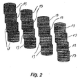
- the flow-controlling coupling layers are according to the invention formed by column layers, cf. Fig. 2 .
- Each column layer comprises a number of columns 13, which are preferably mutually separated.
- the columns 13 may be of almost any arbitrary dimension and be arranged according to desire. However, the columns 13 are preferably cylindrical, and they are preferably equidistantly arranged with a centre distance of approximately 1.8 mm.
- a manufacturing method has been developed, whereby columns of a height of 0.5 to 1.0 mm and a diatneter of 1 mm are embossed in ash-less paper.
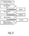
- the manufacturing method is illustrated in Fig. 3 and has been optimized in such a manner that the waste of material has been reduced to almost zero.
- the column layer of the ash less paper can be handled, and the paper burns during sintering with the result that the columns 13 are left in the desired arrangement provided said procedure is carried out at a suitable load.
- a water-based binder system comprising methyl-hydroxy-ethyl-cellulose (Tylose MH300P, Hoechst or Tylose MH 300P2, Clariant) and polyethylene glycol 400 (PEG for synthesis, Merck-Schuchardt).
- the procedures used for mixing the viscous masses are shown in Fig. 3 .
- the dry mixture is subjected to a ball milling in a bottle of polypropylene.
- the desired amounts of water are added during mixing in either a Z-mixer (Werner und Pfleiderer Type LDUK 3IInS) for one hour or by hand mixing. Examples of used plastic compositions are indicated in Table 1.
- the grain size of the precursor powder is, however, not critical.
- the plastic masses were shaped into sheets of a thickness of approximately 1 mm using a roller machine (Cavallin model 013) equipped with an Omron Sysdrive 3G3HV inverter for adjusting the roller speed.
- the masses were wrapped in plastic film (Vita Vrap) in order to minimize the evaporation of water.
- the sealed masses were furthermore rolled in a polyethylene bag (HDPE 70 ⁇ m) in order to avoid the curlings which might otherwise arise during the rolling of the thin sheets.
- the sheets were cut into desired dimensions and dried by one of the following procedures.
- the flatness of the resulting plate depended on the flatness of the plates between which the viscously processed plates were dried.
- the used glass plates have a flatness of ⁇ 25 ⁇ m).
- These processed plates are used directly for stamping columns out of the green ceramic layer in a 200 ⁇ m thick ash-less paper 15, such as Whatman Cat. No. 1.41 150. This stamping renders it possible to fix the columns 13 in the ash-less paper 15. In this manner the column layers can be manufactured in desired arrangements.
- the ash-less paper 15 is removed during the following heating, such as in a cell stack.
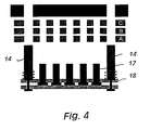
- One mould A comprises a perforated steel plate, cf. Fig. 4 , for providing a layer of a number of columns arranged in a matrix.
- Sprigs 17 in the lower mould have a diameter of 1.1 mm and are placed with a minimum distance of 0.3 mm.
- Some springs of a diameter of approximately 1 mm are optionally provided in some corresponding holes in superposed mould B.
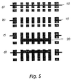
- the entire stamping arrangement comprises the following parts, cf. Figs. 4 and 5 :
- the perforated plate A is used for removing excess, viscously processed plate from the mould after the stamping out, cf. Fig. 5d .
- the use of such a plate implies that it is not necessary to require additional cleaning of the mould, and the excess material can be recycled merely by addition of water.
- the perforated plate B is used for stamping out the columns 13. The diameter of the holes of this plate B determines the diameter of the columns 13 being stamped out.
- the perforated steel plate C is used for supporting the ash-less paper 15 during the stamping procedure.
- the first step of the manufacturing process is to adjust the ash-less paper 15.
- a viscously processed plate 20 is then positioned between the two plates A and B.
- the paper 15 in question and the perforated steel plate C are then placed atop the plate B.
- the fixation columns 14 serve to fix the plates relative to one another.
- the superposed mould with the springs is subsequently mounted.
- the stamping out procedure can be carried out either by means of a rubber hammer or by pressing the stamping parts against one another by means of a uniaxial press.
- the sprigs 17 are pressed upwards into the ceramic plate.
- the ceramic columns are provided which are retained in the holes provided in advance in the paper layer. These ceramic columns simply stick to said paper layer.
- Cylindrical columns 13 are provided by means of dry or almost dry plates, said columns 13 having a thickened foot if the plate contains too much water.
- the individual columns 13 cannot maintain their position unless the sintering procedure is performed at a predetermined load, such as by a sintering of the LSM CCC-layer in a stack during the first heating period.
- a sintering of the column layer which is green by a load of 4.5 to 24.5 kPa at 850 to 1000°C for two hours results in a column layer with a desired arrangement of the columns 13.
- Flow-controlling means can, if desired, be provided between the columns 13, said flow-controlling means comprising strings of a cylindrical or polygonal cross section and optionally being manufactured by way of extrusion of the binder-bound column material or by way of casting of strings with glass-bound sealing materials and arranged in the column plane.
- the strings can be mounted in the flow spaces between the columns a) in the existing spaces in the uniform column pattern, b) after removal of the columns where the strings are to be mounted, or c) after omission of the column extrusion where the flow-controlling strings are to be mounted.
- the flow-controlling means render it possible to establish flow patterns optimizing the general design with respect to minimizing undesired effects, such as a) local temperature gradients caused by uneven area-specific effect development or power consumption, or b) admixing of fluids or gases from the two electrode sides where said fluids or gases may come into contact with one another.
- Some of the sprigs can optionally be removed in response to the fluid-controlling means to be inserted.
Landscapes
- Life Sciences & Earth Sciences (AREA)
- Engineering & Computer Science (AREA)
- Manufacturing & Machinery (AREA)
- Sustainable Development (AREA)
- Sustainable Energy (AREA)
- Chemical & Material Sciences (AREA)
- Chemical Kinetics & Catalysis (AREA)
- Electrochemistry (AREA)
- General Chemical & Material Sciences (AREA)
- Fuel Cell (AREA)
- Inert Electrodes (AREA)
Claims (9)
- Procédé de fabrication d'une pile à combustible à oxyde solide pour une oxydation de gaz, tels que le méthane, le gaz de houille ou l'hydrogène, et qui comprend un électrolyte à oxyde solide, qui est de préférence constitué par YSZ, et où une couche de couplage de régulation du fluide sous la forme d'un certain nombre de colonnes (13) séparées les unes des autres et réalisées dans un matériau de céramique, est placée sur l'anode et sur la cathode, caractérisé en ce que les colonnes (13) sont estampées à partir d'une plaque de matériau de céramique non frittée, lesdites colonnes (13) sont fixées sur une couche de papier, après quoi les colonnes (13) sont soumises à un frittage après avoir été placées sur le côté de l'anode et sur le côté de la cathode, lesdites colonnes (13) étant soumises à une charge mécanique au cours du frittage.
- Procédé selon la revendication 1, caractérisé en ce que les colonnes (13) sont soumises à une charge mécanique comprise entre 4,5 kPa et 24,5 kPa à une température comprise entre 850 °C et 1000 °C pendant deux heures environ au cours du frittage.
- Procédé selon la revendication 1 ou la revendication 2, caractérisé en ce qu'un disque d'interconnexion est placé sur les colonnes (13).
- Procédé selon l'une quelconque des revendications 1 à 3, caractérisé en ce que les colonnes (13) sont disposées de façon équidistante.
- Procédé selon la revendication 4, caractérisé en ce que la distance entre les centres des colonnes (13) est approximativement égale à 1,8 mm.
- Procédé selon l'une quelconque des revendications précédentes 1 à 5, caractérisé en ce que chaque colonne (13) présente une hauteur comprise approximativement entre 0,5 mm et 1,0 mm.
- Procédé selon l'une quelconque des revendications précédentes 1 à 6, caractérisé en ce que chaque colonne (13) présente un diamètre approximativement égal à 1,0 mm.
- Procédé selon l'une quelconque des revendications précédentes 1 à 7, caractérisé en ce que les moyens de régulation de flux se situent entre les colonnes (13).
- Procédé selon l'une quelconque des revendications précédentes 1 à 8, caractérisé en ce que les colonnes (13) sont réalisées dans un matériau de céramique ou dans un mélange de céramique de métal.
Applications Claiming Priority (3)
| Application Number | Priority Date | Filing Date | Title |
|---|---|---|---|
| DKPA200000394 | 2000-03-10 | ||
| DK200000394 | 2000-03-10 | ||
| PCT/DK2001/000157 WO2001067534A1 (fr) | 2000-03-10 | 2001-03-09 | Pile a combustible a oxyde solide et procede de fabrication associe |
Publications (3)
| Publication Number | Publication Date |
|---|---|
| EP1273065A1 EP1273065A1 (fr) | 2003-01-08 |
| EP1273065B1 EP1273065B1 (fr) | 2010-05-05 |
| EP1273065B9 true EP1273065B9 (fr) | 2010-08-11 |
Family
ID=8159317
Family Applications (1)
| Application Number | Title | Priority Date | Filing Date |
|---|---|---|---|
| EP01913733A Expired - Lifetime EP1273065B9 (fr) | 2000-03-10 | 2001-03-09 | Procede de fabrication d'une pile a combustible a oxyde solide |
Country Status (9)
| Country | Link |
|---|---|
| US (1) | US6866957B1 (fr) |
| EP (1) | EP1273065B9 (fr) |
| JP (2) | JP2003526883A (fr) |
| AT (1) | ATE467244T1 (fr) |
| AU (1) | AU2001239208A1 (fr) |
| DE (1) | DE60142036D1 (fr) |
| DK (1) | DK1273065T3 (fr) |
| ES (1) | ES2344545T3 (fr) |
| WO (1) | WO2001067534A1 (fr) |
Families Citing this family (8)
| Publication number | Priority date | Publication date | Assignee | Title |
|---|---|---|---|---|
| EP1328035A1 (fr) * | 2002-01-09 | 2003-07-16 | HTceramix S.A. - High Technology Electroceramics | PEN de pile à combustible à oxydes solide |
| GB2400486B (en) * | 2003-04-09 | 2006-05-10 | Ceres Power Ltd | Densification of ceria based electrolytes |
| DE10342161A1 (de) * | 2003-09-08 | 2005-04-07 | Fraunhofer-Gesellschaft zur Förderung der angewandten Forschung e.V. | Elektrische Kontaktierung für Hochtemperaturbrennstoffzellen sowie Verfahren zur Herstellung einer solchen Kontaktierung |
| US8617456B1 (en) | 2010-03-22 | 2013-12-31 | The United States Of America As Represented By The Secretary Of The Air Force | Bulk low-cost interface-defined laminated materials and their method of fabrication |
| US9120245B1 (en) | 2007-05-09 | 2015-09-01 | The United States Of America As Represented By The Secretary Of The Air Force | Methods for fabrication of parts from bulk low-cost interface-defined nanolaminated materials |
| US9162931B1 (en) * | 2007-05-09 | 2015-10-20 | The United States Of America As Represented By The Secretary Of The Air Force | Tailored interfaces between two dissimilar nano-materials and method of manufacture |
| JP5913200B2 (ja) * | 2013-05-31 | 2016-04-27 | 株式会社ノリタケカンパニーリミテド | 固体酸化物形燃料電池用グリーンシート |
| KR101860079B1 (ko) * | 2016-03-30 | 2018-05-21 | 울산과학기술원 | 고체 산화물 연료전지용 애노드 소재의 제조 방법 |
Family Cites Families (4)
| Publication number | Priority date | Publication date | Assignee | Title |
|---|---|---|---|---|
| US5256499A (en) * | 1990-11-13 | 1993-10-26 | Allied Signal Aerospace | Monolithic solid oxide fuel cells with integral manifolds |
| JPH0878040A (ja) * | 1994-09-01 | 1996-03-22 | Mitsubishi Heavy Ind Ltd | 固体電解質燃料電池の接続構造 |
| JPH10302818A (ja) * | 1997-04-24 | 1998-11-13 | Osaka Gas Co Ltd | 燃料電池 |
| JP2000053424A (ja) * | 1998-07-24 | 2000-02-22 | Sulzer Hexis Ag | インタ―コネクタのコ―ティングのためのペロブスカイト、インタ―コネクタ及び燃料セル電池 |
-
2001
- 2001-03-09 DE DE60142036T patent/DE60142036D1/de not_active Expired - Lifetime
- 2001-03-09 JP JP2001566202A patent/JP2003526883A/ja not_active Withdrawn
- 2001-03-09 US US10/221,410 patent/US6866957B1/en not_active Expired - Fee Related
- 2001-03-09 EP EP01913733A patent/EP1273065B9/fr not_active Expired - Lifetime
- 2001-03-09 AT AT01913733T patent/ATE467244T1/de not_active IP Right Cessation
- 2001-03-09 DK DK01913733.0T patent/DK1273065T3/da active
- 2001-03-09 WO PCT/DK2001/000157 patent/WO2001067534A1/fr not_active Ceased
- 2001-03-09 ES ES01913733T patent/ES2344545T3/es not_active Expired - Lifetime
- 2001-03-09 AU AU2001239208A patent/AU2001239208A1/en not_active Abandoned
-
2012
- 2012-12-06 JP JP2012267240A patent/JP5581367B2/ja not_active Expired - Fee Related
Also Published As
| Publication number | Publication date |
|---|---|
| JP5581367B2 (ja) | 2014-08-27 |
| WO2001067534A1 (fr) | 2001-09-13 |
| EP1273065A1 (fr) | 2003-01-08 |
| JP2003526883A (ja) | 2003-09-09 |
| US20050048340A1 (en) | 2005-03-03 |
| EP1273065B1 (fr) | 2010-05-05 |
| ES2344545T3 (es) | 2010-08-31 |
| DK1273065T3 (da) | 2010-08-02 |
| ATE467244T1 (de) | 2010-05-15 |
| DE60142036D1 (de) | 2010-06-17 |
| AU2001239208A1 (en) | 2001-09-17 |
| US6866957B1 (en) | 2005-03-15 |
| JP2013080710A (ja) | 2013-05-02 |
Similar Documents
| Publication | Publication Date | Title |
|---|---|---|
| JP5581367B2 (ja) | 固体酸化物燃料電池及び前記固体酸化物燃料電池の製造方法 | |
| EP1645007B1 (fr) | Feuille d'electrolyte texturee | |
| US6344426B1 (en) | Porous ceramic sheet, process for producing the same, and setter for use in the process | |
| US10008726B2 (en) | Metal supported solid oxide fuel cell | |
| ES2829048T3 (es) | Proceso de formación de electrolitos | |
| RU2699815C2 (ru) | Способ формирования электролита | |
| EP0584551B1 (fr) | Pile à combustible à oxyde solide et électrode à combustible pour celle-ci | |
| EP1035610A2 (fr) | Monocellule et structure de pile pour batterie de piles à combustible à oxydes solides | |
| KR100499651B1 (ko) | 고온연료전지용전기화학적활성소자 | |
| JP2010505235A (ja) | 異なる組成の領域を備えた電解質シートおよびそれを含む燃料電池デバイス | |
| EP0586264B1 (fr) | Conducteur d'ions d'oxygène et pile à combustible à électrolyte solide | |
| KR101685386B1 (ko) | 저온 동시소결에 의한 연료극 지지형 고체산화물 셀 및 그 제조방법 | |
| Tai et al. | Tape casting and sintering of strontium‐doped lanthanum chromite for a planar solid oxide fuel cell bipolar plate | |
| WO2008032862A2 (fr) | Ensemble électrodes à électrolyte et procédé de production correspondant | |
| JP4377856B2 (ja) | 平板型燃料電池セルの製造方法 | |
| US11594748B2 (en) | Setter plates and manufacturing methods for ceramic-anode solid oxide fuel cells | |
| JP4508592B2 (ja) | 燃料電池セルの製法 | |
| JP2013077395A (ja) | アノード基板、固体酸化物形燃料電池及びアノード基板の製造方法 | |
| KR102100257B1 (ko) | 고강도 프레임이 적용된 고체산화물연료전지용 평판형 단전지 | |
| KR101940712B1 (ko) | 고체 산화물 연료 전지 및 이의 제조방법 | |
| JP2024139407A (ja) | 固体酸化物形燃料電池セル | |
| JPH07114924A (ja) | 固体電解質型燃料電池セル | |
| Armstrong et al. | Chemical interactions between interconnect and electrode materials during sintering in solid oxide fuel cells | |
| JP2005158528A (ja) | 燃料電池セル及び燃料電池 |
Legal Events
| Date | Code | Title | Description |
|---|---|---|---|
| PUAI | Public reference made under article 153(3) epc to a published international application that has entered the european phase |
Free format text: ORIGINAL CODE: 0009012 |
|
| 17P | Request for examination filed |
Effective date: 20020819 |
|
| AK | Designated contracting states |
Kind code of ref document: A1 Designated state(s): AT BE CH CY DE DK ES FI FR GB GR IE IT LI LU MC NL PT SE TR |
|
| AX | Request for extension of the european patent |
Free format text: AL;LT;LV;MK;RO;SI |
|
| 17Q | First examination report despatched |
Effective date: 20030325 |
|
| APBN | Date of receipt of notice of appeal recorded |
Free format text: ORIGINAL CODE: EPIDOSNNOA2E |
|
| APBR | Date of receipt of statement of grounds of appeal recorded |
Free format text: ORIGINAL CODE: EPIDOSNNOA3E |
|
| APAA | Appeal reference recorded |
Free format text: ORIGINAL CODE: EPIDOS REFN |
|
| APAF | Appeal reference modified |
Free format text: ORIGINAL CODE: EPIDOSCREFNE |
|
| APAF | Appeal reference modified |
Free format text: ORIGINAL CODE: EPIDOSCREFNE |
|
| RAP1 | Party data changed (applicant data changed or rights of an application transferred) |
Owner name: DANMARKS TEKNISKE UNIVERSITET |
|
| APBT | Appeal procedure closed |
Free format text: ORIGINAL CODE: EPIDOSNNOA9E |
|
| GRAP | Despatch of communication of intention to grant a patent |
Free format text: ORIGINAL CODE: EPIDOSNIGR1 |
|
| RTI1 | Title (correction) |
Free format text: A METHOD OF MANUFACTURING A SOLID OXIDE FUEL CELL |
|
| GRAS | Grant fee paid |
Free format text: ORIGINAL CODE: EPIDOSNIGR3 |
|
| GRAA | (expected) grant |
Free format text: ORIGINAL CODE: 0009210 |
|
| AK | Designated contracting states |
Kind code of ref document: B1 Designated state(s): AT BE CH CY DE DK ES FI FR GB GR IE IT LI LU MC NL PT SE TR |
|
| REG | Reference to a national code |
Ref country code: GB Ref legal event code: FG4D |
|
| REG | Reference to a national code |
Ref country code: CH Ref legal event code: EP |
|
| REG | Reference to a national code |
Ref country code: IE Ref legal event code: FG4D |
|
| REG | Reference to a national code |
Ref country code: CH Ref legal event code: NV Representative=s name: BRAUNPAT BRAUN EDER AG |
|
| REF | Corresponds to: |
Ref document number: 60142036 Country of ref document: DE Date of ref document: 20100617 Kind code of ref document: P |
|
| REG | Reference to a national code |
Ref country code: DK Ref legal event code: T3 |
|
| REG | Reference to a national code |
Ref country code: SE Ref legal event code: TRGR |
|
| REG | Reference to a national code |
Ref country code: NL Ref legal event code: T3 |
|
| REG | Reference to a national code |
Ref country code: ES Ref legal event code: FG2A Ref document number: 2344545 Country of ref document: ES Kind code of ref document: T3 |
|
| PG25 | Lapsed in a contracting state [announced via postgrant information from national office to epo] |
Ref country code: AT Free format text: LAPSE BECAUSE OF FAILURE TO SUBMIT A TRANSLATION OF THE DESCRIPTION OR TO PAY THE FEE WITHIN THE PRESCRIBED TIME-LIMIT Effective date: 20100505 |
|
| PG25 | Lapsed in a contracting state [announced via postgrant information from national office to epo] |
Ref country code: CY Free format text: LAPSE BECAUSE OF FAILURE TO SUBMIT A TRANSLATION OF THE DESCRIPTION OR TO PAY THE FEE WITHIN THE PRESCRIBED TIME-LIMIT Effective date: 20100505 Ref country code: GR Free format text: LAPSE BECAUSE OF FAILURE TO SUBMIT A TRANSLATION OF THE DESCRIPTION OR TO PAY THE FEE WITHIN THE PRESCRIBED TIME-LIMIT Effective date: 20100806 |
|
| PG25 | Lapsed in a contracting state [announced via postgrant information from national office to epo] |
Ref country code: PT Free format text: LAPSE BECAUSE OF FAILURE TO SUBMIT A TRANSLATION OF THE DESCRIPTION OR TO PAY THE FEE WITHIN THE PRESCRIBED TIME-LIMIT Effective date: 20100906 |
|
| PLBE | No opposition filed within time limit |
Free format text: ORIGINAL CODE: 0009261 |
|
| STAA | Information on the status of an ep patent application or granted ep patent |
Free format text: STATUS: NO OPPOSITION FILED WITHIN TIME LIMIT |
|
| 26N | No opposition filed |
Effective date: 20110208 |
|
| REG | Reference to a national code |
Ref country code: DE Ref legal event code: R097 Ref document number: 60142036 Country of ref document: DE Effective date: 20110207 |
|
| PG25 | Lapsed in a contracting state [announced via postgrant information from national office to epo] |
Ref country code: MC Free format text: LAPSE BECAUSE OF NON-PAYMENT OF DUE FEES Effective date: 20110331 |
|
| REG | Reference to a national code |
Ref country code: IE Ref legal event code: MM4A |
|
| PG25 | Lapsed in a contracting state [announced via postgrant information from national office to epo] |
Ref country code: IE Free format text: LAPSE BECAUSE OF NON-PAYMENT OF DUE FEES Effective date: 20110309 |
|
| PG25 | Lapsed in a contracting state [announced via postgrant information from national office to epo] |
Ref country code: LU Free format text: LAPSE BECAUSE OF NON-PAYMENT OF DUE FEES Effective date: 20110309 |
|
| PG25 | Lapsed in a contracting state [announced via postgrant information from national office to epo] |
Ref country code: TR Free format text: LAPSE BECAUSE OF FAILURE TO SUBMIT A TRANSLATION OF THE DESCRIPTION OR TO PAY THE FEE WITHIN THE PRESCRIBED TIME-LIMIT Effective date: 20100505 |
|
| PGFP | Annual fee paid to national office [announced via postgrant information from national office to epo] |
Ref country code: FI Payment date: 20140327 Year of fee payment: 14 Ref country code: DK Payment date: 20140325 Year of fee payment: 14 Ref country code: NL Payment date: 20140326 Year of fee payment: 14 Ref country code: CH Payment date: 20140327 Year of fee payment: 14 Ref country code: SE Payment date: 20140327 Year of fee payment: 14 |
|
| PGFP | Annual fee paid to national office [announced via postgrant information from national office to epo] |
Ref country code: ES Payment date: 20140326 Year of fee payment: 14 Ref country code: IT Payment date: 20140324 Year of fee payment: 14 Ref country code: FR Payment date: 20140317 Year of fee payment: 14 |
|
| PGFP | Annual fee paid to national office [announced via postgrant information from national office to epo] |
Ref country code: GB Payment date: 20140327 Year of fee payment: 14 |
|
| PGFP | Annual fee paid to national office [announced via postgrant information from national office to epo] |
Ref country code: BE Payment date: 20140328 Year of fee payment: 14 |
|
| PGFP | Annual fee paid to national office [announced via postgrant information from national office to epo] |
Ref country code: DE Payment date: 20140327 Year of fee payment: 14 |
|
| REG | Reference to a national code |
Ref country code: DE Ref legal event code: R119 Ref document number: 60142036 Country of ref document: DE |
|
| REG | Reference to a national code |
Ref country code: DK Ref legal event code: EBP Effective date: 20150331 |
|
| PG25 | Lapsed in a contracting state [announced via postgrant information from national office to epo] |
Ref country code: FI Free format text: LAPSE BECAUSE OF NON-PAYMENT OF DUE FEES Effective date: 20150309 |
|
| REG | Reference to a national code |
Ref country code: CH Ref legal event code: PL |
|
| GBPC | Gb: european patent ceased through non-payment of renewal fee |
Effective date: 20150309 |
|
| PG25 | Lapsed in a contracting state [announced via postgrant information from national office to epo] |
Ref country code: SE Free format text: LAPSE BECAUSE OF NON-PAYMENT OF DUE FEES Effective date: 20150310 |
|
| REG | Reference to a national code |
Ref country code: SE Ref legal event code: EUG |
|
| REG | Reference to a national code |
Ref country code: NL Ref legal event code: MM Effective date: 20150401 |
|
| PG25 | Lapsed in a contracting state [announced via postgrant information from national office to epo] |
Ref country code: IT Free format text: LAPSE BECAUSE OF NON-PAYMENT OF DUE FEES Effective date: 20150309 |
|
| REG | Reference to a national code |
Ref country code: FR Ref legal event code: ST Effective date: 20151130 |
|
| PG25 | Lapsed in a contracting state [announced via postgrant information from national office to epo] |
Ref country code: CH Free format text: LAPSE BECAUSE OF NON-PAYMENT OF DUE FEES Effective date: 20150331 Ref country code: LI Free format text: LAPSE BECAUSE OF NON-PAYMENT OF DUE FEES Effective date: 20150331 Ref country code: GB Free format text: LAPSE BECAUSE OF NON-PAYMENT OF DUE FEES Effective date: 20150309 Ref country code: DE Free format text: LAPSE BECAUSE OF NON-PAYMENT OF DUE FEES Effective date: 20151001 |
|
| PG25 | Lapsed in a contracting state [announced via postgrant information from national office to epo] |
Ref country code: FR Free format text: LAPSE BECAUSE OF NON-PAYMENT OF DUE FEES Effective date: 20150331 |
|
| REG | Reference to a national code |
Ref country code: ES Ref legal event code: FD2A Effective date: 20160427 |
|
| PG25 | Lapsed in a contracting state [announced via postgrant information from national office to epo] |
Ref country code: DK Free format text: LAPSE BECAUSE OF NON-PAYMENT OF DUE FEES Effective date: 20150331 |
|
| PG25 | Lapsed in a contracting state [announced via postgrant information from national office to epo] |
Ref country code: ES Free format text: LAPSE BECAUSE OF NON-PAYMENT OF DUE FEES Effective date: 20150310 |
|
| PG25 | Lapsed in a contracting state [announced via postgrant information from national office to epo] |
Ref country code: NL Free format text: LAPSE BECAUSE OF NON-PAYMENT OF DUE FEES Effective date: 20150401 |
|
| PG25 | Lapsed in a contracting state [announced via postgrant information from national office to epo] |
Ref country code: BE Free format text: LAPSE BECAUSE OF NON-PAYMENT OF DUE FEES Effective date: 20150331 |