EP1273310A1 - Anordnung für Autoklavsysteme - Google Patents
Anordnung für Autoklavsysteme Download PDFInfo
- Publication number
- EP1273310A1 EP1273310A1 EP02450111A EP02450111A EP1273310A1 EP 1273310 A1 EP1273310 A1 EP 1273310A1 EP 02450111 A EP02450111 A EP 02450111A EP 02450111 A EP02450111 A EP 02450111A EP 1273310 A1 EP1273310 A1 EP 1273310A1
- Authority
- EP
- European Patent Office
- Prior art keywords
- vessel
- pipe
- chamber
- vacuum pump
- collector
- Prior art date
- Legal status (The legal status is an assumption and is not a legal conclusion. Google has not performed a legal analysis and makes no representation as to the accuracy of the status listed.)
- Granted
Links
Images

Classifications
-
- A—HUMAN NECESSITIES
- A61—MEDICAL OR VETERINARY SCIENCE; HYGIENE
- A61L—METHODS OR APPARATUS FOR STERILISING MATERIALS OR OBJECTS IN GENERAL; DISINFECTION, STERILISATION OR DEODORISATION OF AIR; CHEMICAL ASPECTS OF BANDAGES, DRESSINGS, ABSORBENT PADS OR SURGICAL ARTICLES; MATERIALS FOR BANDAGES, DRESSINGS, ABSORBENT PADS OR SURGICAL ARTICLES
- A61L2/00—Disinfection or sterilisation of materials or objects, in general; Accessories therefor
- A61L2/24—Apparatus using programmed or automatic operation
-
- A—HUMAN NECESSITIES
- A61—MEDICAL OR VETERINARY SCIENCE; HYGIENE
- A61L—METHODS OR APPARATUS FOR STERILISING MATERIALS OR OBJECTS IN GENERAL; DISINFECTION, STERILISATION OR DEODORISATION OF AIR; CHEMICAL ASPECTS OF BANDAGES, DRESSINGS, ABSORBENT PADS OR SURGICAL ARTICLES; MATERIALS FOR BANDAGES, DRESSINGS, ABSORBENT PADS OR SURGICAL ARTICLES
- A61L2/00—Disinfection or sterilisation of materials or objects, in general; Accessories therefor
- A61L2/02—Disinfection or sterilisation of materials or objects, in general; Accessories therefor using physical processes
- A61L2/04—Heat
- A61L2/06—Hot gas
- A61L2/07—Steam
Definitions
- the invention relates to an autoclave for sterilising medical and in particular dental appliances and instruments.
- an autoclave is known e.g. from EP 0 992 247 A1.
- the aim of the invention is to provide a simplified and cheap solution requiring less space. According to the invention these aims are achieved in that, coming from the condenser, the condensate (water-steam mixture) is passed into a separator vessel, that a connecting pipe extends from the upper area of said separator vessel, preferably from its highest point, to the vacuum pump, that said separator vessel is provided in its lower area, preferably at its lowest point, with a one-way valve which may be spring-loaded which in the presence of an appropriate pressure difference permits discharge of fluid from the separator vessel into a collector vessel, that a pressure pipe coming from the vacuum pump ends in the upper area of said collector vessel and that the pipe leads into the main tank of the autoclave from the lower area of said collector vessel.
- the condensate collects in the separator chamber when the condenser and the vacuum pump are operated, the one-way valve is kept closed by the vacuum applied in this chamber and by connecting the outlet of the vacuum pump to the collector vessel; when the condensation cycle is finished, the pressure in the separator vessel and the collector vessel is equalised by switching off the vacuum pump so that due to the weight of the separated liquid pressing on it the liquid runs off from the separator vessel into the collector vessel; when the condensation cycle starts anew, the liquid contained in the collector is passed through the connecting pipe to the main tank by connecting the outlet of the vacuum pump to the collector vessel, while at the same time, in most cases somewhat deferred, condensate is passed anew into the separator vessel through the pipe coming from the condenser.
- the various connecting pipes may completely be dispensed with; preferably the separator vessel and the collector vessel have identical design and the shape of a pot, and are mounted in a somewhat staggered arrangement on a mounting plate so that the one-way valve connecting the two vessels may be positioned directly in the mounting plate.
- the other pipes may be appropriately mounted in the mounting plate or in the bottom area of the collector vessel which corresponds to the top area of the separator vessel when mounted upside down.
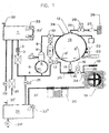
- Fig. 1 shows a diagrammatic view of the autoclave known from the prior art to which the invention may be applied. It has the following features:
- the process water taken from a tank 1 through a filter 2, is injected by a pump 3 in a steam generator 5.
- the steam generator 5 is equipped with an eccentric positioned heating element 4 and a temperature sensor 6.
- a safety valve 7 is connected to the steam generator.
- a tube 9 links the steam dome 8 of the generator 5 to a three way valve 10 and depending on it's position, to the chamber 13 or the condensation accumulator 11.
- the steam reaches the chamber 13 and the pressure in the chamber increases.
- the steam streams through a one way valve 14, an embranchement 15, through a tube 34 and a drain valve 16 to a condenser 19 and is pumped off by the vacuum pump 20 into a waste tank 31.
- the drain valve 16 is kept closed and the chamber is connected to the condensation collector 11 through branching 15 to a tube 35 to another three way valve 17, its position in these phases depending on the position of the above mentioned three way valve 10.
- the condensation collector 11 is directly linked to the chamber but it's temperature is lower. This "cold point” creates a physical phenomenon similar to a little vacuum, sucking out the condensation from the chamber 13. From here it is discharged in regular intervals into the steam generator 5 to be heated up again. This process according to the invention saves water, energy and time.
- An air-inlet-valve 18 is connected to the pipe 34 downstream of the valve 15 but upstream of the condenser 19. Through this valve 18 and its pipe 36, a precisely predetermined quantity of air is added to the condenser-bound steam for two reasons: Firstly to obtain a perfect and continuous drain of the condenser and secondly to allow the membrane pump 20 to suck directly water thereby guaranteeing a low noise level.
- vacuum losses are therefore determined in relation to the flow rate of the membrane pump 20 in a way to reach easily the predetermined optimal values in all the vacuum phases.
- a time out has been fixed for the first three vacuum pulses (ex: 3min). If the vacuum pulses do not reach within this time out the predetermined value (ex: -0,80 bar), the maximum negative pressure is registered and the cycle goes on.
- the microprocessor calculates the theoretical complementary vacuum and defines the value of the 4th additional pulse with the registered values so that the theoretical air residual percentage can be reached.
- both three way valves 10 and 17 are switched in a position which, as explained before, separates the chamber 13 completely from the steam generator 5 and leads the condensation to the condensation collector 11.
- the chamber 13 and especially its content, the load remains even during the pressure pulse as dry as possible, which brings a reduction of the condensation passing through the condenser 19 and the vacuum pump 20 during the vacuum phase. All such condensation heats them up and reduces needlessly their efficiency, so any reduction of condensation passing through the condenser and the vacuum pump is a valuable progress.
- the dry state of the chamber 13 and its load improves the drying process and reduces its duration.
- the internal temperature of the steam generator 5 shall be reduced to about 105°C which allows for a direct draining by opening the waste valve 21 leading to the waste tank 31 without cooling the steam.
- the chamber 13 is provided with two temperature sensors 6' and 6" in order to obtain, at each phase of the process-cycle, with sufficient reliability the temperature prevailing in the chamber.
- connections 22 for a pressure test and 23 for a temperature test can be used.
- the chamber 13, having a thermal insulation, is heated by an external heating element 12, its temperature is controlled by an external sensor 24 completely independent of the internal ones.
- the chamber 13 In order to introduce external sterile air, the chamber 13 is connected to an air inlet by a tube 25, through a valve 28, a one way valve 27 and a bacteriological filter 26. It is necessary, at the end of the sterilisation process, to equilibrate the chamber to the atmospheric pressure prior to the opening of the door.
- drain cocks are foreseen respectively 29 for the pure water, and 29' for the waste. Additionally, a connection to an external pure water tank is provided in a way to have an automatic refilling of the pure water tank 1 by a water pump 30. Both tanks 1 and 31 are most completely watertight and need external connections 32 and 32'.
- the tanks are equipped with water level sensors 33, 33' and 33", in order to prevent under-or overfilling.
- the condenser 19 is air cooled but a water cooled condenser can be used without altering the generic concept of the invention or leaving its scope.
- the represented membrane pump 20 can be replaced by any other pump used for such application.
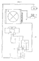
- the condensate may not just be passed into a waste water tank 31 as in the prior art, but now it is possible, with a clearly reduced power of the vacuum pump 20, to pass the condensate into a combined tank 38 from which it is available again.
- a condensate pipe 39 leads from the condenser 19 to the upper area of a precipitation vessel 40.
- a vacuum pipe 41 leads from the head of the precipitation vessel 40 to the suction pipe of the vacuum pump 20.
- a pressure pipe 42 leads from the outlet of the vacuum pump to the upper area of a collector vessel 43, and a transfer pipe 44 leads from the bottom area of said collector vessel to the combined tank 38.
- a one-way valve 45 is provided which permits fluid passing only in the direction from the precipitation vessel 40 to the collector vessel 43.
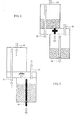
- the precipitation vessel 40 and the collector vessel 43 have identical design and each has the shape of a pot. With the open side the two vessels are mounted on either side of a mounting plate 46, the separator vessel 40 being mounted on its upper side and the collector vessel 43 on its lower side. Thus the connection between the two vessels becomes a bore hole in the mounting plate 46 in which also the check valve or flap trap 45 is positioned.
- the vessels 40, 43 may either be screwed onto the mounting plate or connected with it by a flange and mounting screws with an intermediate seal.
- the fittings for fixing the condensate pipe 39 and the pressure pipe 42 are appropriately provided in the mounting plate so that the vessels 40, 43 need only one mounting point each either on the bottom (or on the top when mounted upside down).
- Figs. 3 to 6 show the sequence of flow of the condensate in the course of a cycle of operation of the autoclave.
- Fig. 3 shows the precipitation and collector unit according to the invention in the empty state, the condensate pipe 39 extends into the upper area of the precipitation vessel 40, with the vacuum pipe 41 extending from the top surface of that vessel.
- the precipitation vessel 40 is mounted on the mounting plate 46 where the fixture for the condensate pipe 39 is positioned.
- the connection between the two vessels 40, 43 - with a diagrammatic view of a check valve 45 inserted in the drawing ⁇ is positioned in the mounting plate 46.
- the pipe 44 extends preferably up to the upper area of the collector vessel 43, but also has an opening 47 through which the liquid may be discharged at its lower end.
- Fig. 3 shows the situation arising when the autoclave chamber 13 has been completely emptied (Fig. 1) and the valve 16 (Fig. 2) is closed and the vacuum pump 20 out of operation: in this state the pressure between the (suction) inlet 41 and the (pressure) outlet 42 of the vacuum pump 20 is equalised which results in a pressure equalisation between the separator vessel 40 and the collector vessel 43, and the weight of the water pressing on the flap valve 45 forces the valve in the open position so that the water flows from the separator vessel 40 into the collector vessel 43 and may also flow into the transfer pipe 44 in so far as said transfer pipe forms a U-shaped sack.
- Fig. 4 shows the situation in which the liquid is to be passed from the collector vessel 43 into the tank 38 (Fig. 2). This may be done either in a separate step of the cycle or at the beginning of the next condensation step: the valve 16 is aired (or the condensate pipe 39 after the valve 16 if a separate step is provided), then the vacuum pump 20 is put into operation so that low pressure forms again in the separator vessel 40, while high pressure forms in the collector vessel 43. This results in the closing of the flap valve 45 and passing of this liquid through the transfer pipe 44 into the tank 38 due to the pressure exerted on the liquid in the collector vessel 43; when all the liquid is passed through, gas alone flows through the collector vessel 43 and the transfer pipe 44.
- the condensate may not just be pumped, as in the prior art, with a small and compact vacuum pump 20 into a tank at the lowest point of the apparatus from where it has to be passed manually or with a separate pump into the storage tank 1 at the highest point of the apparatus, but it has become possible to perform that transport of the condensate automatically and at an expenditure which is extremely low compared to the result achieved.
- the invention may come in different variations, e.g. the two vessels may be of a substantially cylindrical design with an intermediate bottom in which a flap valve is positioned, however, with the condensate pipe 39 and the pressure pipe 42 ending at the surface of the jacket. It is of course also possible to design the two vessels discretely, i.e. not on a common carrying device, but this is not preferred because of the increased demand for fittings, holding devices and space and will be useful only in special cases of application. Of course it is possible to fix the vacuum pump 20 in an appropriate manner dependent on its design also on the mounting plate 46 and dispense with pipes 41 and/or 42 or use pipes of a particularly simple design.
Landscapes
- Health & Medical Sciences (AREA)
- Epidemiology (AREA)
- Life Sciences & Earth Sciences (AREA)
- Animal Behavior & Ethology (AREA)
- General Health & Medical Sciences (AREA)
- Public Health (AREA)
- Veterinary Medicine (AREA)
- Apparatus For Disinfection Or Sterilisation (AREA)
- Dental Tools And Instruments Or Auxiliary Dental Instruments (AREA)
- Heating, Cooling, Or Curing Plastics Or The Like In General (AREA)
Applications Claiming Priority (2)
| Application Number | Priority Date | Filing Date | Title |
|---|---|---|---|
| AT10312001 | 2001-07-03 | ||
| AT10312001 | 2001-07-03 |
Publications (2)
| Publication Number | Publication Date |
|---|---|
| EP1273310A1 true EP1273310A1 (de) | 2003-01-08 |
| EP1273310B1 EP1273310B1 (de) | 2007-10-24 |
Family
ID=3684341
Family Applications (1)
| Application Number | Title | Priority Date | Filing Date |
|---|---|---|---|
| EP02450111A Expired - Lifetime EP1273310B1 (de) | 2001-07-03 | 2002-05-03 | Anordnung für Autoklavsysteme |
Country Status (7)
| Country | Link |
|---|---|
| US (1) | US6926874B2 (de) |
| EP (1) | EP1273310B1 (de) |
| AT (1) | ATE376429T1 (de) |
| AU (1) | AU785078B2 (de) |
| CZ (1) | CZ301902B6 (de) |
| DE (1) | DE60223109T2 (de) |
| ES (1) | ES2294095T3 (de) |
Cited By (1)
| Publication number | Priority date | Publication date | Assignee | Title |
|---|---|---|---|---|
| CN103239740A (zh) * | 2013-05-16 | 2013-08-14 | 成都科尔医药技术有限公司 | 连续混合灭菌设备 |
Families Citing this family (16)
| Publication number | Priority date | Publication date | Assignee | Title |
|---|---|---|---|---|
| ITMI20051342A1 (it) * | 2005-07-14 | 2007-01-15 | W & H Sterilization Srl | Generatore di vaspore perfezionato per un'autoclave |
| DE602007006517D1 (de) * | 2007-11-13 | 2010-06-24 | Cisa Spa | Dampfsterilisationssystem |
| US8448004B2 (en) | 2008-10-27 | 2013-05-21 | Netapp, Inc. | Power savings using dynamic storage cluster membership |
| US20100278688A1 (en) * | 2008-11-24 | 2010-11-04 | Damien Tanaka | Containerized Medical Waste Treatment System and Related Method |
| US8454901B1 (en) | 2009-05-06 | 2013-06-04 | Clarence J. Snyder, III | Mobile apparatus and method to sterilize surgical trays |
| FI20115350A0 (fi) * | 2011-04-12 | 2011-04-12 | Steris Europe Inc | Laite kiintoaineen erottamiseksi biojätesuspensiosta |
| US20160015841A1 (en) * | 2013-03-11 | 2016-01-21 | Scican Ltd. | Condensation assembly and method |
| US9616143B2 (en) | 2013-07-17 | 2017-04-11 | Progressive Sterilization, Llc | Mobile apparatus and method for sterilizing one or more surgical trays with integrable transfer and storage system |
| BR112016020874B1 (pt) | 2014-03-10 | 2023-11-21 | Progressive Sterilization, Llc | Aparelho para esterilizar e armazenar equipamentos |
| JP6472643B2 (ja) * | 2014-11-25 | 2019-02-20 | 株式会社タカゾノテクノロジー | 蒸気滅菌器 |
| JP6472644B2 (ja) * | 2014-11-25 | 2019-02-20 | 株式会社タカゾノテクノロジー | 蒸気滅菌器 |
| JP6472645B2 (ja) * | 2014-11-25 | 2019-02-20 | 株式会社タカゾノテクノロジー | 蒸気滅菌器 |
| JP6513299B2 (ja) * | 2017-02-09 | 2019-05-15 | 株式会社アルバック | 真空乾燥装置及び方法 |
| US10086100B1 (en) | 2017-07-28 | 2018-10-02 | Pmbs, Llc | Mobile sterilization apparatus and method for using the same |
| CN115634298A (zh) * | 2022-10-24 | 2023-01-24 | 张家港市嘉瑞制药机械有限公司 | 一种脉动灭菌柜 |
| USD1065537S1 (en) | 2024-07-30 | 2025-03-04 | Stericube Surgical Systems, Llc | Filter separator |
Citations (3)
| Publication number | Priority date | Publication date | Assignee | Title |
|---|---|---|---|---|
| US5217688A (en) * | 1991-01-25 | 1993-06-08 | Lersner Wolf A | Process for the disposal of medical waste |
| EP0992247A1 (de) * | 1998-10-05 | 2000-04-12 | Dentalwerk Bürmoos Gesellschaft M.B.H. | Autoklav |
| DE19930546C1 (de) * | 1999-06-29 | 2000-06-21 | Melagapparate Gmbh & Co Kg | Dampfsterilisator |
Family Cites Families (5)
| Publication number | Priority date | Publication date | Assignee | Title |
|---|---|---|---|---|
| CH655548B (de) * | 1982-03-31 | 1986-04-30 | ||
| US4583301A (en) * | 1984-01-26 | 1986-04-22 | U-Op Management & Consultants Ltd. | Variable volume vacuum drying chamber |
| DE4204444C1 (de) * | 1992-02-14 | 1993-05-19 | Krankenhausentsorgungs Gmbh, 1000 Berlin, De | |
| DE4211744C1 (en) * | 1992-04-03 | 1993-04-22 | Melagapparate Gmbh & Co Kg, 1000 Berlin, De | Steam steriliser, providing shorter heating time - consists of autoclave with pressure chamber in side wall, water tank and steam generator |
| IT1298428B1 (it) * | 1998-02-20 | 2000-01-10 | M O Com S R L | Procedimento ed apparecchiatura per la sterilizzazione a vapore in particolare per usi odontoiatrici |
-
2002
- 2002-05-03 DE DE60223109T patent/DE60223109T2/de not_active Expired - Lifetime
- 2002-05-03 EP EP02450111A patent/EP1273310B1/de not_active Expired - Lifetime
- 2002-05-03 AT AT02450111T patent/ATE376429T1/de active
- 2002-05-03 ES ES02450111T patent/ES2294095T3/es not_active Expired - Lifetime
- 2002-05-08 AU AU38239/02A patent/AU785078B2/en not_active Expired
- 2002-06-12 US US10/170,175 patent/US6926874B2/en not_active Expired - Lifetime
- 2002-06-12 CZ CZ20022044A patent/CZ301902B6/cs not_active IP Right Cessation
Patent Citations (3)
| Publication number | Priority date | Publication date | Assignee | Title |
|---|---|---|---|---|
| US5217688A (en) * | 1991-01-25 | 1993-06-08 | Lersner Wolf A | Process for the disposal of medical waste |
| EP0992247A1 (de) * | 1998-10-05 | 2000-04-12 | Dentalwerk Bürmoos Gesellschaft M.B.H. | Autoklav |
| DE19930546C1 (de) * | 1999-06-29 | 2000-06-21 | Melagapparate Gmbh & Co Kg | Dampfsterilisator |
Cited By (2)
| Publication number | Priority date | Publication date | Assignee | Title |
|---|---|---|---|---|
| CN103239740A (zh) * | 2013-05-16 | 2013-08-14 | 成都科尔医药技术有限公司 | 连续混合灭菌设备 |
| CN103239740B (zh) * | 2013-05-16 | 2015-05-20 | 成都科尔医药技术有限公司 | 连续混合灭菌设备 |
Also Published As
| Publication number | Publication date |
|---|---|
| ATE376429T1 (de) | 2007-11-15 |
| CZ301902B6 (cs) | 2010-07-28 |
| US6926874B2 (en) | 2005-08-09 |
| DE60223109D1 (de) | 2007-12-06 |
| CZ20022044A3 (cs) | 2003-02-12 |
| ES2294095T3 (es) | 2008-04-01 |
| DE60223109T2 (de) | 2008-08-14 |
| AU3823902A (en) | 2003-01-09 |
| US20030007915A1 (en) | 2003-01-09 |
| AU785078B2 (en) | 2006-09-14 |
| EP1273310B1 (de) | 2007-10-24 |
Similar Documents
| Publication | Publication Date | Title |
|---|---|---|
| EP0992247B1 (de) | Autoklave | |
| US6926874B2 (en) | Autoclave | |
| EP1273311B1 (de) | Autoklav | |
| US7089885B2 (en) | Steam-heating apparatus | |
| JP3510010B2 (ja) | 真空蒸気加熱装置 | |
| JP3507866B2 (ja) | 蒸気加熱装置 | |
| JP3544236B2 (ja) | 蒸気加熱装置 | |
| JP4409715B2 (ja) | 蒸気加熱装置 | |
| JP5047426B2 (ja) | 蒸気加熱装置 | |
| JP7203410B2 (ja) | 蒸気滅菌器 | |
| JP3463152B2 (ja) | 蒸気加熱装置 | |
| CN116928995A (zh) | 一种蒸汽灭菌器干燥判定方法 | |
| JP3537206B2 (ja) | 蒸気加熱装置 | |
| JP5047425B2 (ja) | 蒸気加熱装置 | |
| RU18348U1 (ru) | Паровой стерилизатор | |
| JPH10148480A (ja) | 熱交換器 | |
| JP2025540436A (ja) | 蒸気滅菌器システム | |
| JPH0557101A (ja) | 水溶液の蒸発濃縮装置 | |
| JPH0884923A (ja) | 蒸気加熱装置 | |
| JP2001293361A (ja) | 蒸気加熱装置 | |
| JPH0584403B2 (de) |
Legal Events
| Date | Code | Title | Description |
|---|---|---|---|
| PUAI | Public reference made under article 153(3) epc to a published international application that has entered the european phase |
Free format text: ORIGINAL CODE: 0009012 |
|
| AK | Designated contracting states |
Kind code of ref document: A1 Designated state(s): AT BE CH CY DE DK ES FI FR GB GR IE IT LI LU MC NL PT SE TR |
|
| AX | Request for extension of the european patent |
Free format text: AL;LT;LV;MK;RO;SI |
|
| 17P | Request for examination filed |
Effective date: 20030703 |
|
| AKX | Designation fees paid |
Designated state(s): AT BE CH CY DE DK ES FI FR GB GR IE IT LI LU MC NL PT SE TR |
|
| RAP1 | Party data changed (applicant data changed or rights of an application transferred) |
Owner name: W & H STERILIZATION S.R.L. |
|
| 17Q | First examination report despatched |
Effective date: 20040804 |
|
| GRAP | Despatch of communication of intention to grant a patent |
Free format text: ORIGINAL CODE: EPIDOSNIGR1 |
|
| GRAS | Grant fee paid |
Free format text: ORIGINAL CODE: EPIDOSNIGR3 |
|
| GRAA | (expected) grant |
Free format text: ORIGINAL CODE: 0009210 |
|
| AK | Designated contracting states |
Kind code of ref document: B1 Designated state(s): AT BE CH CY DE DK ES FI FR GB GR IE IT LI LU MC NL PT SE TR |
|
| REG | Reference to a national code |
Ref country code: GB Ref legal event code: FG4D |
|
| REG | Reference to a national code |
Ref country code: CH Ref legal event code: EP |
|
| REG | Reference to a national code |
Ref country code: IE Ref legal event code: FG4D |
|
| REF | Corresponds to: |
Ref document number: 60223109 Country of ref document: DE Date of ref document: 20071206 Kind code of ref document: P |
|
| RAP2 | Party data changed (patent owner data changed or rights of a patent transferred) |
Owner name: W & H STERILIZATION S.R.L. |
|
| RAP2 | Party data changed (patent owner data changed or rights of a patent transferred) |
Owner name: W & H STERILIZATION S.R.L. |
|
| REG | Reference to a national code |
Ref country code: SE Ref legal event code: TRGR |
|
| REG | Reference to a national code |
Ref country code: CH Ref legal event code: NV Representative=s name: NOVAGRAAF INTERNATIONAL SA |
|
| NLT2 | Nl: modifications (of names), taken from the european patent patent bulletin |
Owner name: W & H STERILIZATION S.R.L. Effective date: 20071212 |
|
| NLT2 | Nl: modifications (of names), taken from the european patent patent bulletin |
Owner name: W & H STERILIZATION S.R.L. Effective date: 20071226 |
|
| REG | Reference to a national code |
Ref country code: ES Ref legal event code: FG2A Ref document number: 2294095 Country of ref document: ES Kind code of ref document: T3 |
|
| ET | Fr: translation filed | ||
| PG25 | Lapsed in a contracting state [announced via postgrant information from national office to epo] |
Ref country code: PT Free format text: LAPSE BECAUSE OF FAILURE TO SUBMIT A TRANSLATION OF THE DESCRIPTION OR TO PAY THE FEE WITHIN THE PRESCRIBED TIME-LIMIT Effective date: 20080324 |
|
| PG25 | Lapsed in a contracting state [announced via postgrant information from national office to epo] |
Ref country code: DK Free format text: LAPSE BECAUSE OF FAILURE TO SUBMIT A TRANSLATION OF THE DESCRIPTION OR TO PAY THE FEE WITHIN THE PRESCRIBED TIME-LIMIT Effective date: 20071024 |
|
| PGFP | Annual fee paid to national office [announced via postgrant information from national office to epo] |
Ref country code: CH Payment date: 20080519 Year of fee payment: 7 |
|
| PLBE | No opposition filed within time limit |
Free format text: ORIGINAL CODE: 0009261 |
|
| STAA | Information on the status of an ep patent application or granted ep patent |
Free format text: STATUS: NO OPPOSITION FILED WITHIN TIME LIMIT |
|
| PGFP | Annual fee paid to national office [announced via postgrant information from national office to epo] |
Ref country code: BE Payment date: 20080428 Year of fee payment: 7 |
|
| 26N | No opposition filed |
Effective date: 20080725 |
|
| PGFP | Annual fee paid to national office [announced via postgrant information from national office to epo] |
Ref country code: NL Payment date: 20080516 Year of fee payment: 7 |
|
| PG25 | Lapsed in a contracting state [announced via postgrant information from national office to epo] |
Ref country code: MC Free format text: LAPSE BECAUSE OF NON-PAYMENT OF DUE FEES Effective date: 20080531 |
|
| PG25 | Lapsed in a contracting state [announced via postgrant information from national office to epo] |
Ref country code: GR Free format text: LAPSE BECAUSE OF FAILURE TO SUBMIT A TRANSLATION OF THE DESCRIPTION OR TO PAY THE FEE WITHIN THE PRESCRIBED TIME-LIMIT Effective date: 20080125 |
|
| PG25 | Lapsed in a contracting state [announced via postgrant information from national office to epo] |
Ref country code: FI Free format text: LAPSE BECAUSE OF FAILURE TO SUBMIT A TRANSLATION OF THE DESCRIPTION OR TO PAY THE FEE WITHIN THE PRESCRIBED TIME-LIMIT Effective date: 20071024 |
|
| PG25 | Lapsed in a contracting state [announced via postgrant information from national office to epo] |
Ref country code: IE Free format text: LAPSE BECAUSE OF NON-PAYMENT OF DUE FEES Effective date: 20080505 |
|
| PG25 | Lapsed in a contracting state [announced via postgrant information from national office to epo] |
Ref country code: CY Free format text: LAPSE BECAUSE OF FAILURE TO SUBMIT A TRANSLATION OF THE DESCRIPTION OR TO PAY THE FEE WITHIN THE PRESCRIBED TIME-LIMIT Effective date: 20071024 |
|
| BERE | Be: lapsed |
Owner name: W & H STERILIZATION S.R.L. Effective date: 20090531 |
|
| REG | Reference to a national code |
Ref country code: CH Ref legal event code: PL |
|
| PG25 | Lapsed in a contracting state [announced via postgrant information from national office to epo] |
Ref country code: CH Free format text: LAPSE BECAUSE OF NON-PAYMENT OF DUE FEES Effective date: 20090531 Ref country code: LI Free format text: LAPSE BECAUSE OF NON-PAYMENT OF DUE FEES Effective date: 20090531 |
|
| NLV4 | Nl: lapsed or anulled due to non-payment of the annual fee |
Effective date: 20091201 |
|
| PG25 | Lapsed in a contracting state [announced via postgrant information from national office to epo] |
Ref country code: NL Free format text: LAPSE BECAUSE OF NON-PAYMENT OF DUE FEES Effective date: 20091201 |
|
| PG25 | Lapsed in a contracting state [announced via postgrant information from national office to epo] |
Ref country code: BE Free format text: LAPSE BECAUSE OF NON-PAYMENT OF DUE FEES Effective date: 20090531 |
|
| PG25 | Lapsed in a contracting state [announced via postgrant information from national office to epo] |
Ref country code: LU Free format text: LAPSE BECAUSE OF NON-PAYMENT OF DUE FEES Effective date: 20080503 |
|
| PG25 | Lapsed in a contracting state [announced via postgrant information from national office to epo] |
Ref country code: TR Free format text: LAPSE BECAUSE OF FAILURE TO SUBMIT A TRANSLATION OF THE DESCRIPTION OR TO PAY THE FEE WITHIN THE PRESCRIBED TIME-LIMIT Effective date: 20071024 |
|
| REG | Reference to a national code |
Ref country code: FR Ref legal event code: PLFP Year of fee payment: 15 |
|
| REG | Reference to a national code |
Ref country code: FR Ref legal event code: PLFP Year of fee payment: 16 |
|
| REG | Reference to a national code |
Ref country code: FR Ref legal event code: PLFP Year of fee payment: 17 |
|
| PGFP | Annual fee paid to national office [announced via postgrant information from national office to epo] |
Ref country code: IT Payment date: 20210414 Year of fee payment: 20 Ref country code: FR Payment date: 20210414 Year of fee payment: 20 Ref country code: DE Payment date: 20210413 Year of fee payment: 20 |
|
| PGFP | Annual fee paid to national office [announced via postgrant information from national office to epo] |
Ref country code: SE Payment date: 20210414 Year of fee payment: 20 Ref country code: AT Payment date: 20210419 Year of fee payment: 20 Ref country code: GB Payment date: 20210413 Year of fee payment: 20 Ref country code: ES Payment date: 20210601 Year of fee payment: 20 |
|
| REG | Reference to a national code |
Ref country code: DE Ref legal event code: R071 Ref document number: 60223109 Country of ref document: DE |
|
| REG | Reference to a national code |
Ref country code: GB Ref legal event code: PE20 Expiry date: 20220502 |
|
| REG | Reference to a national code |
Ref country code: AT Ref legal event code: MK07 Ref document number: 376429 Country of ref document: AT Kind code of ref document: T Effective date: 20220503 |
|
| PG25 | Lapsed in a contracting state [announced via postgrant information from national office to epo] |
Ref country code: GB Free format text: LAPSE BECAUSE OF EXPIRATION OF PROTECTION Effective date: 20220502 |
|
| REG | Reference to a national code |
Ref country code: ES Ref legal event code: FD2A Effective date: 20220803 |
|
| PG25 | Lapsed in a contracting state [announced via postgrant information from national office to epo] |
Ref country code: ES Free format text: LAPSE BECAUSE OF EXPIRATION OF PROTECTION Effective date: 20220504 |