EP1273354A2 - Dispositif d'alimentation en poudre et procédé d'application de poudre sur un substrat - Google Patents
Dispositif d'alimentation en poudre et procédé d'application de poudre sur un substrat Download PDFInfo
- Publication number
- EP1273354A2 EP1273354A2 EP02013681A EP02013681A EP1273354A2 EP 1273354 A2 EP1273354 A2 EP 1273354A2 EP 02013681 A EP02013681 A EP 02013681A EP 02013681 A EP02013681 A EP 02013681A EP 1273354 A2 EP1273354 A2 EP 1273354A2
- Authority
- EP
- European Patent Office
- Prior art keywords
- powder
- conveying device
- gas stream
- powder conveying
- gas flow
- Prior art date
- Legal status (The legal status is an assumption and is not a legal conclusion. Google has not performed a legal analysis and makes no representation as to the accuracy of the status listed.)
- Granted
Links
Images

Classifications
-
- B—PERFORMING OPERATIONS; TRANSPORTING
- B05—SPRAYING OR ATOMISING IN GENERAL; APPLYING FLUENT MATERIALS TO SURFACES, IN GENERAL
- B05B—SPRAYING APPARATUS; ATOMISING APPARATUS; NOZZLES
- B05B7/00—Spraying apparatus for discharge of liquids or other fluent materials from two or more sources, e.g. of liquid and air, of powder and gas
- B05B7/14—Spraying apparatus for discharge of liquids or other fluent materials from two or more sources, e.g. of liquid and air, of powder and gas designed for spraying particulate materials
- B05B7/1404—Arrangements for supplying particulate material
- B05B7/1413—Apparatus to be carried on or by a person, e.g. by hand; Apparatus comprising a container fixed to the discharge device
- B05B7/1422—Apparatus to be carried on or by a person, e.g. by hand; Apparatus comprising a container fixed to the discharge device the means for supplying particulate material comprising moving mechanical means, e.g. to impart vibration
-
- H—ELECTRICITY
- H01—ELECTRIC ELEMENTS
- H01M—PROCESSES OR MEANS, e.g. BATTERIES, FOR THE DIRECT CONVERSION OF CHEMICAL ENERGY INTO ELECTRICAL ENERGY
- H01M4/00—Electrodes
- H01M4/86—Inert electrodes with catalytic activity, e.g. for fuel cells
- H01M4/88—Processes of manufacture
- H01M4/8825—Methods for deposition of the catalytic active composition
- H01M4/8828—Coating with slurry or ink
-
- H—ELECTRICITY
- H01—ELECTRIC ELEMENTS
- H01M—PROCESSES OR MEANS, e.g. BATTERIES, FOR THE DIRECT CONVERSION OF CHEMICAL ENERGY INTO ELECTRICAL ENERGY
- H01M8/00—Fuel cells; Manufacture thereof
- H01M8/10—Fuel cells with solid electrolytes
- H01M8/1004—Fuel cells with solid electrolytes characterised by membrane-electrode assemblies [MEA]
-
- Y—GENERAL TAGGING OF NEW TECHNOLOGICAL DEVELOPMENTS; GENERAL TAGGING OF CROSS-SECTIONAL TECHNOLOGIES SPANNING OVER SEVERAL SECTIONS OF THE IPC; TECHNICAL SUBJECTS COVERED BY FORMER USPC CROSS-REFERENCE ART COLLECTIONS [XRACs] AND DIGESTS
- Y02—TECHNOLOGIES OR APPLICATIONS FOR MITIGATION OR ADAPTATION AGAINST CLIMATE CHANGE
- Y02E—REDUCTION OF GREENHOUSE GAS [GHG] EMISSIONS, RELATED TO ENERGY GENERATION, TRANSMISSION OR DISTRIBUTION
- Y02E60/00—Enabling technologies; Technologies with a potential or indirect contribution to GHG emissions mitigation
- Y02E60/30—Hydrogen technology
- Y02E60/50—Fuel cells
Definitions
- the invention relates to a powder conveying device with a receptacle for powder, which has a discharge port for the removal of powder the receptacle in a gas stream, and with a gas flow Einkopplungsvorraum for the receptacle.
- Such a powder conveying device is for example from the DE 197 57 492 A1.
- the invention is based on the object, a powder conveying device to create, with the most diverse types of powder under Prevent agglomeration of the powder.
- This object is according to the invention in the powder conveying device mentioned above achieved in that by the gas flow coupling device a first gas stream can be coupled into the receptacle through which a powder cloud is formed in the receptacle that a second gas stream into the receptacle for atomization of the powder cloud einkoppelbar is and that on the discharge port by means of a scoop powder from the Powder cloud is dischargeable.
- the powder By the first gas flow, the powder is in a receiving space of the receiving container held in suspension and by the second gas flow the powder cloud formed is swirled, that is atomized. To this This prevents agglomeration of the powder in the receiving space.
- the gas flows and in particular their relationship to each other can promote various types of powders; it can be done in addition to light powders heavy metal powder such as unsupported Promote catalyst powder. In particular, it is also possible to use powders with nanoparticles promote.
- the powder By the removal of the powder from the receiving space by means of the Scoop tube, wherein the powder is discharged by means of a gas flow, by the superposition of the first gas stream and the second gas stream comes about, then the powder can promote agglomeration and so for example spray on a carrier.
- the Position of an inlet opening of the scoop tube relative to the coupling-in areas the gas flows is another parameter through which the Powder production is optimized depending on the powder material.
- the first gas stream in the receptacle in particular directed directed directed substantially against the direction of gravity.
- the powder barrier is formed by a sintered plate, which has correspondingly fine pores, although gas-permeable but are not permeable to powder.
- the sintered plate can be especially so make sure that even the finest powder particles can not fall through.
- the powder barrier then forms one with respect to the direction of gravity lower boundary of a receiving space of the receptacle, so that through the gas flow through the powder barrier therethrough Powder in the receiving space is stable in the balance.
- the second gas stream in the receptacle relative to the direction of gravity above the first gas flow coupled to swirl the suspended powder cloud, wherein over the from the first gas stream and the second gas stream resulting gas flow powder is discharged through the scoop tube.
- angle deviations for exact collinear alignment may be provided, which are up to 50 °.
- angle deviations for exact collinear alignment may be provided if the second gas stream in the receptacle substantially in the opposite direction to the first gas flow is directed.
- the second gas stream coupled via a tube, which is provided with one or more openings is.
- the gas flow can be easily coupled, wherein the reduction of the volume of the recording room over the corresponding one Einkopplungsvorraum is minimized.
- Openings can be set to the desired direction of the second gas stream.
- the opening or openings based on an axis of the receptacle arranged substantially symmetrically are. This can be ensured, especially in connection with a symmetrical powder barrier that is in the receiving space can not form dead centers with respect to the flow conditions, in which it could come to a Pulververbackung.
- Diameter of the inlet opening can be varied, for example via a corresponding muzzle attachment, which a desired opening diameter Has.
- the position of an inlet opening of the Scoop tube is adjustable in the receptacle and in particular in situ is adjustable. It can then be by targeted adjustment of this position optimal production result and thus discharge result. To this Way can achieve a homogeneous promotion, so that, for example Make spray layers with high reproducibility, namely for most diverse types of powder.
- the position of the inlet opening is related in the vertical direction adjustable in the direction of gravity, that is, the scoop can be moved up or down.
- the inlet opening in the receptacle so is positioned so that they are substantially at an axis of the receptacle is arranged, that is on an axis of symmetry, so as to an effective discharge via the gas stream from the receptacle to to care.
- volume flow of the first gas stream is adjustable
- volume flow of the second gas stream is adjustable and in particular the ratio of the two volume flows is adjustable. That way optimum homogenization and discharge, ie powder conveying, reach, with a variety of powders can be used.
- a nozzle is connected to the scoop tube to so over the powder conveying device according to the invention a dry spray layer to be able to apply to a carrier.
- the powder conveying device is mechanically homogenized Powder provided, that is, the receptacle takes homogenized Powder on.
- the powder delivery device itself performs no mechanical Homogenization by, but a homogenization in terms of Discharge, that is, prevents agglomeration of already mechanical homogenized powder.
- the receptacle is powder supplied from a powder supply and in particular fed continuously, for example, to be able to continuously apply powder to a carrier.
- the powder conveying device can be described as Use a powder applicator of powder on a carrier, wherein then in particular the scoop is connected to a flat nozzle.
- a grinding device provides the homogenized with respect to the particle size Powder ready and the powder conveyor ensures a homogeneous (even) order. In particular, can dry over them Carry out spray coatings on carriers with high reproducibility.
- the invention further relates to a method for powder application to a Carrier.
- homogenized Powder is fed to a powder conveying device, from which powder a gas stream is discharged by means of a scoop, wherein in the Powder conveyor via a first gas flow a floating powder cloud is formed, atomizes the powder cloud via a second gas stream is and wherein an inlet opening of the scoop in the atomized Powder cloud is directed to Pulveraustragung.
- the inventive method already has in connection with the Powder conveying device according to the invention described advantages. Especially Thin homogeneous layers with high reproducibility can be produced produce.
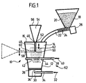
- a receptacle 12 is provided, in which a receiving space 14 is formed.
- the Receiving space 14 preferably has an axis of symmetry and related to this axis of symmetry a round cross-section.
- the receiving space 14 is then cylindrical or conical. boundary walls of the receiving space 14 are polished inside.
- a container lid 16th arranged at one with respect to the direction of gravity.
- This container lid 16 can be opened in particular to to be pumped powder into the receiving space 14, if not continuous Powder supply is provided.
- a powder supply 18 which, for example, funnel-shaped and the homogenized Powder 20 receives, via a line 22, which for example via the container lid 16 opens into the receiving space 14, powder provided.
- this powder 20 can be provided continuously.
- the powder 20 is in particular by nanoparticles having a particle size formed in the order of 30 mm or smaller.
- a screw 24 is provided, which is driven by a motor 26.
- the receiving space 14 completed by a powder barrier 28.
- This powder barrier prevents powder from falling out of the receiving space 14, However, it is gas flow permeable over its entire cross section substantially.
- the powder barrier 28 is through a sintered plate formed impermeable to fine powder particles, but not for Gas flow.
- a distribution space 30 for a first Gas stream 32 is arranged below the powder barrier 28 .
- the first gas stream 32 is thereby via a line 34 is guided into the distribution space 30, wherein the conduit 34 has a mouth opening 36, from which the first gas stream into the distribution stream 30th can enter and then the powder barrier 28 in the receiving space 14, this mouth opening 36 with respect to the direction of gravity after is directed above.
- the mouth opening 36 is in particular at the Positioned axis of the receiving space 14, so that a symmetrical gas flow is ensured to the receiving space 14.
- a second gas stream 40 can be in the receiving space 14, wherein this line 38 above the line 34, based on the direction of gravity, is guided in the receiving space 14.
- This line 38 has openings 42, 44 arranged within the receiving space 14, which are directed towards the powder barrier 28, so that the second Gas stream 40 when entering the receiving space 14 substantially the first gas stream 32 as it enters the powder barrier 28 into the receiving space 14 is opposite.
- the openings 42, 44 are so arranged to be substantially symmetrical about an axis of the receiving space 14 are.
- the receptacle 12 is provided with a discharge port 46, via the Powder from the receiving space 14 can be discharged, for example, a Coat carrier.
- the discharge port 46 is disposed in the container lid 16 and through an opening formed.
- a scoop tube 48 in led the receiving space 14, wherein this scoop an inlet 50 for powder, via the powder from the receiving space 14 can be discharged is.
- the end 52 facing away from the inlet opening 50 is for this purpose a flat nozzle 54 is coupled, in which case via an outlet end 56 of this flat nozzle 54 a carrier with powder from the receiving space 14 besprühbar is.
- the inlet opening 50 is in particular in the region of the axis of the receiving space 14, that is, has substantially the same distance to the surrounding walls of the receptacle 12.
- the position of the inlet opening 50 relative to the Powder barrier 28 is variable, that is adjustable, so that the vertical Position of the inlet opening 50 in the receiving space 14 is adjustable.
- the opening diameter of the inlet opening 50 itself is adjustable, for example, via a corresponding Attachment that can be positioned on the scoop tube 48.
- a discharge port 58 is laterally on a wall arranged in the receptacle 12 and accordingly is a scoop 60 guided laterally into the receiving space 14 via this discharge connection 58. It can also be provided here that the vertical height of the scoop 60th is adjustable by, for example, a bellows or the like and a positioning device of this scoop tube 60 is vertically displaceable.
- the powder conveying device functions as follows:
- the receiving space 14 is filled with mechanically homogenized powder, where the particle size with high statistical frequency at an average lies. This can be done either by a powder batch over the container lid 16 is filled in the receiving space 14, or that Powder from the powder supply 18 via the line 22 into the receiving space 14th is promoted in particular continuously.
- the first gas stream 32 Via the line 34 and the powder barrier 28, the first gas stream 32, at in particular, it is an inert gas stream such as a nitrogen gas stream or argon gas stream, coupled into the receiving space 14, wherein it is in the coupling substantially against the direction of gravity is directed.
- This first gas stream 32 then holds the powder in one Powder cloud 62 in the receiving space 14 in suspension and ensures that powder discharged via the inlet opening 50 through the scoop tube 48 in the flat nozzle 54 becomes.
- the second gas stream which in turn is an inert gas stream, and in particular formed by the same gas as the first gas stream, passes over the Line 38 and the openings 42, 44 in the receiving space 14 a and is thereby substantially opposite to the first gas flow 32 when entering. It causes a turbulence of the powder cloud 62, that is one Atomization of the powder cloud 62. This will agglomeration and Cogglomeration of powder particles in the powder 20 prevented, so that over the powder delivery device 10 also apply the finest powder to a carrier leaves, so that layer thicknesses, for example, produce less than 40 microns and, in particular, layers of a thickness of the order of magnitude 5 ⁇ m can be produced.
- the crushed, homogenized Powder is provided to the receiving space 14, that is in this There is no mechanical homogenization in terms of particle size, but a homogeneous discharge from this.
- the gas flow injection device as 62 in its entirety, which includes the conduit 38, conduit 34 and powder barrier 28 the two gas streams 32 and 40 in a certain volume flow in couple in the receiving space 14, in particular in a certain ratio couple to each other.
- the gas flows are so set that the powder can be optimally discharged. Due to the adjustability the height of the inlet opening 50 of the scoop tube 48 above the powder barrier 28 results in a further parameter with which the inventive Adjust powder feeder 10 to the powder to be processed leaves.
- About the powder conveying device according to the invention can be, for example spray dry electrochemical layers, leaving a thin layer is reachable.
- supported catalysts can also be used as powders be (precious metals on carbon particles) or electrolyte powder.
- a grinding device 64 is provided (FIG. 2).
- the homogenized powder from the powder delivery device 10 in turn comes from the grinder 64, which ensures that even very fine Powder (nanoparticle powder) still a high degree of homogenization exhibit.
- the sprayed powder 80 can be, for example, via a pair of rollers 90th Roll on the carrier or fix it on a press.
- electrochemical layers for Hydrogen membrane fuel cells direct methanol membrane fuel cells or for gas diffusion electrodes. It can be done accordingly also electrochemical layers for reactors, reformers or batteries produce. It is also possible to coat general surfaces with powder, For example, powder coatings can be carried out from surfaces.
- Powder conveying device 10 can be used a variety of powder types and depending on the used Powders can be over the powder conveying device according to the invention 10 set the optimal operating parameters.
Landscapes
- Engineering & Computer Science (AREA)
- Manufacturing & Machinery (AREA)
- Chemical & Material Sciences (AREA)
- Chemical Kinetics & Catalysis (AREA)
- Electrochemistry (AREA)
- General Chemical & Material Sciences (AREA)
- Nozzles (AREA)
- Application Of Or Painting With Fluid Materials (AREA)
- Air Transport Of Granular Materials (AREA)
- Devices And Processes Conducted In The Presence Of Fluids And Solid Particles (AREA)
- Powder Metallurgy (AREA)
- Coating Apparatus (AREA)
Applications Claiming Priority (2)
| Application Number | Priority Date | Filing Date | Title |
|---|---|---|---|
| DE10134498 | 2001-07-02 | ||
| DE10134498A DE10134498C2 (de) | 2001-07-02 | 2001-07-02 | Pulverfördervorrichtung und Verfahren zur Pulverauftragung auf einen Träger |
Publications (3)
| Publication Number | Publication Date |
|---|---|
| EP1273354A2 true EP1273354A2 (fr) | 2003-01-08 |
| EP1273354A3 EP1273354A3 (fr) | 2005-05-11 |
| EP1273354B1 EP1273354B1 (fr) | 2008-12-24 |
Family
ID=7691937
Family Applications (1)
| Application Number | Title | Priority Date | Filing Date |
|---|---|---|---|
| EP02013681A Expired - Lifetime EP1273354B1 (fr) | 2001-07-02 | 2002-07-01 | Dispositif d'alimentation en poudre et procédé d'application de poudre sur un substrat |
Country Status (4)
| Country | Link |
|---|---|
| EP (1) | EP1273354B1 (fr) |
| AT (1) | ATE418390T1 (fr) |
| DE (2) | DE10134498C2 (fr) |
| DK (1) | DK1273354T3 (fr) |
Cited By (4)
| Publication number | Priority date | Publication date | Assignee | Title |
|---|---|---|---|---|
| EP1582266A1 (fr) * | 2004-03-31 | 2005-10-05 | Deutsches Zentrum für Luft- und Raumfahrt e.V. | Procédé et dispositif pour la fabrication d'une couche fonctionnelle électrochimique ou électrique ou thermique |
| DE102004017161A1 (de) * | 2004-03-31 | 2005-10-20 | Deutsch Zentr Luft & Raumfahrt | Pulverpartikel-Aufbringverfahren und Aufbringvorrichtung für Pulverpartikel |
| EP1659655A3 (fr) * | 2004-11-23 | 2006-08-30 | Deutsches Zentrum für Luft- und Raumfahrt e.V. | Procédé de fabrication d'un assemblage électrode-membrane et assemblage électrode-membrane |
| EP1704927A3 (fr) * | 2005-03-24 | 2007-05-23 | Fraunhofer-Gesellschaft zur Förderung der angewandten Forschung e.V. | Dispositif et procédé pour la production d'un aérosol |
Citations (1)
| Publication number | Priority date | Publication date | Assignee | Title |
|---|---|---|---|---|
| DE19757492A1 (de) | 1997-12-23 | 1999-07-01 | Deutsch Zentr Luft & Raumfahrt | Verfahren zur Herstellung von Funktionsschichten für Brennstoffzellen |
Family Cites Families (6)
| Publication number | Priority date | Publication date | Assignee | Title |
|---|---|---|---|---|
| FR2163182A5 (en) * | 1972-12-07 | 1973-07-20 | Traversac Rene | Powder spray dispenser - using perforated rising air line to pick up from fluidised bed |
| IT1184973B (it) * | 1985-03-08 | 1987-10-28 | Gabriele Missier | Cabina perfezionata per verniciatura elettrostatica |
| DE3602388C1 (de) * | 1986-01-28 | 1987-03-12 | Gema Ransburg Ag | Pulverbeschichtungseinrichtung |
| DE4039061C2 (de) * | 1990-12-07 | 2003-11-27 | Hans G Platsch | Pudernebelgenerator |
| US5603566A (en) * | 1995-11-21 | 1997-02-18 | Abb Flexible Automation Inc. | Powder hopper with internal air assist |
| DE19624303A1 (de) * | 1996-06-18 | 1998-01-02 | Kohlenstaubtechnik Dr Schoppe | Verfahren und Vorrichtung zum Fluidisieren von feinkörnigem Schüttgut |
-
2001
- 2001-07-02 DE DE10134498A patent/DE10134498C2/de not_active Expired - Lifetime
-
2002
- 2002-07-01 DE DE50213144T patent/DE50213144D1/de not_active Expired - Lifetime
- 2002-07-01 AT AT02013681T patent/ATE418390T1/de not_active IP Right Cessation
- 2002-07-01 EP EP02013681A patent/EP1273354B1/fr not_active Expired - Lifetime
- 2002-07-01 DK DK02013681T patent/DK1273354T3/da active
Patent Citations (1)
| Publication number | Priority date | Publication date | Assignee | Title |
|---|---|---|---|---|
| DE19757492A1 (de) | 1997-12-23 | 1999-07-01 | Deutsch Zentr Luft & Raumfahrt | Verfahren zur Herstellung von Funktionsschichten für Brennstoffzellen |
Cited By (4)
| Publication number | Priority date | Publication date | Assignee | Title |
|---|---|---|---|---|
| EP1582266A1 (fr) * | 2004-03-31 | 2005-10-05 | Deutsches Zentrum für Luft- und Raumfahrt e.V. | Procédé et dispositif pour la fabrication d'une couche fonctionnelle électrochimique ou électrique ou thermique |
| DE102004017161A1 (de) * | 2004-03-31 | 2005-10-20 | Deutsch Zentr Luft & Raumfahrt | Pulverpartikel-Aufbringverfahren und Aufbringvorrichtung für Pulverpartikel |
| EP1659655A3 (fr) * | 2004-11-23 | 2006-08-30 | Deutsches Zentrum für Luft- und Raumfahrt e.V. | Procédé de fabrication d'un assemblage électrode-membrane et assemblage électrode-membrane |
| EP1704927A3 (fr) * | 2005-03-24 | 2007-05-23 | Fraunhofer-Gesellschaft zur Förderung der angewandten Forschung e.V. | Dispositif et procédé pour la production d'un aérosol |
Also Published As
| Publication number | Publication date |
|---|---|
| DE50213144D1 (de) | 2009-02-05 |
| DE10134498A1 (de) | 2003-01-30 |
| DE10134498C2 (de) | 2003-05-15 |
| ATE418390T1 (de) | 2009-01-15 |
| EP1273354B1 (fr) | 2008-12-24 |
| DK1273354T3 (da) | 2009-04-14 |
| EP1273354A3 (fr) | 2005-05-11 |
Similar Documents
| Publication | Publication Date | Title |
|---|---|---|
| DE69311481T2 (de) | Durch sprühkristallisation hergestellter träger für einen polymerisationskatalysator | |
| DE69420393T2 (de) | Apparat und verfahren zum befeuchten von pulver | |
| EP0926753A2 (fr) | Méthode de fabrication de couches fonctionelles pour piles à combustible | |
| DE19881316B4 (de) | Verfahren und Vorrichtung zur Herstellung von Metallpulver durch Zerstäubung | |
| DE102009048397A1 (de) | Atmosphärendruckplasmaverfahren zur Herstellung oberflächenmodifizierter Partikel und von Beschichtungen | |
| EP0663241A1 (fr) | Buse de pulverisation | |
| EP1042093B1 (fr) | Procede et dispositif pour produire des poudres fines par atomisation de matieres fondues avec des gaz | |
| AT409235B (de) | Verfahren und vorrichtung zur herstellung von metallpulver | |
| DE3035168A1 (de) | Vorrichtung zur behandlung von pulvern | |
| EP0570446A1 (fr) | Dispositif d'enduction d'une chambre de compression avec un lubrifiant. | |
| EP1273354B1 (fr) | Dispositif d'alimentation en poudre et procédé d'application de poudre sur un substrat | |
| WO2007017159A1 (fr) | Procede de production de pellets d'uree | |
| DE3889316T2 (de) | Vorrichtung und Verfahren zur Verteilung von Distanzhaltern einer Flüssigkristall-Anzeige. | |
| DE3883256T2 (de) | Vorrichtung und verfahren zur atomisierung von flüssigkeiten, insbesondere geschmolzenen metallen. | |
| DE2923493A1 (de) | Verfahren und vorrichtung zum entgasen von geschmolzenem metall | |
| EP1523695B1 (fr) | Systeme de buses pour appliquer un liquide sur un substrat | |
| DE60110176T2 (de) | Verfahren und Vorrichtung zur Herstellung von Flüssigkeiten mit ultrafeinen, zusammengesetzten Partikeln | |
| EP2387456B1 (fr) | Procédé pour modifier la surface de particules et dispositif correspondant | |
| DE68910819T2 (de) | Entladungsgerät. | |
| DE202010015304U1 (de) | Düse | |
| DE69011357T2 (de) | Schneidverfahren und Vorrichtung. | |
| DE3407871A1 (de) | Verfahren und vorrichtung zur erzeugung eines massenstrom- oder volumenstromkonstanten gas-feststoffteilchen-freistrahls bestimmter geschwindigkeit | |
| DE102004038413B4 (de) | Verfahren und Vorrichtung zur Herstellung einer Beschichtung mit räumlich variierenden Eigenschaften | |
| EP4341019A1 (fr) | Appareil de coulée et procédé de coulée pour la production de matériaux composites à matrice métallique | |
| DE69603583T2 (de) | Herstellungs-verfahren und vorrichtung eines mit partikeln beschichteten substrates |
Legal Events
| Date | Code | Title | Description |
|---|---|---|---|
| PUAI | Public reference made under article 153(3) epc to a published international application that has entered the european phase |
Free format text: ORIGINAL CODE: 0009012 |
|
| AK | Designated contracting states |
Kind code of ref document: A2 Designated state(s): AT BE BG CH CY CZ DE DK EE ES FI FR GB GR IE IT LI LU MC NL PT SE SK TR |
|
| AX | Request for extension of the european patent |
Free format text: AL;LT;LV;MK;RO;SI |
|
| PUAL | Search report despatched |
Free format text: ORIGINAL CODE: 0009013 |
|
| AK | Designated contracting states |
Kind code of ref document: A3 Designated state(s): AT BE BG CH CY CZ DE DK EE ES FI FR GB GR IE IT LI LU MC NL PT SE SK TR |
|
| AX | Request for extension of the european patent |
Extension state: AL LT LV MK RO SI |
|
| 17P | Request for examination filed |
Effective date: 20050818 |
|
| AKX | Designation fees paid |
Designated state(s): AT BE BG CH CY CZ DE DK EE ES FI FR GB GR IE IT LI LU MC NL PT SE SK TR |
|
| 17Q | First examination report despatched |
Effective date: 20060905 |
|
| GRAP | Despatch of communication of intention to grant a patent |
Free format text: ORIGINAL CODE: EPIDOSNIGR1 |
|
| GRAS | Grant fee paid |
Free format text: ORIGINAL CODE: EPIDOSNIGR3 |
|
| GRAA | (expected) grant |
Free format text: ORIGINAL CODE: 0009210 |
|
| AK | Designated contracting states |
Kind code of ref document: B1 Designated state(s): AT BE BG CH CY CZ DE DK EE ES FI FR GB GR IE IT LI LU MC NL PT SE SK TR |
|
| REG | Reference to a national code |
Ref country code: GB Ref legal event code: FG4D Free format text: NOT ENGLISH |
|
| REG | Reference to a national code |
Ref country code: CH Ref legal event code: EP Ref country code: CH Ref legal event code: NV Representative=s name: ISLER & PEDRAZZINI AG |
|
| REG | Reference to a national code |
Ref country code: IE Ref legal event code: FG4D Free format text: LANGUAGE OF EP DOCUMENT: GERMAN |
|
| REF | Corresponds to: |
Ref document number: 50213144 Country of ref document: DE Date of ref document: 20090205 Kind code of ref document: P |
|
| REG | Reference to a national code |
Ref country code: DK Ref legal event code: T3 Ref country code: SE Ref legal event code: TRGR |
|
| PG25 | Lapsed in a contracting state [announced via postgrant information from national office to epo] |
Ref country code: FI Free format text: LAPSE BECAUSE OF FAILURE TO SUBMIT A TRANSLATION OF THE DESCRIPTION OR TO PAY THE FEE WITHIN THE PRESCRIBED TIME-LIMIT Effective date: 20081224 |
|
| REG | Reference to a national code |
Ref country code: IE Ref legal event code: FD4D |
|
| PG25 | Lapsed in a contracting state [announced via postgrant information from national office to epo] |
Ref country code: IE Free format text: LAPSE BECAUSE OF FAILURE TO SUBMIT A TRANSLATION OF THE DESCRIPTION OR TO PAY THE FEE WITHIN THE PRESCRIBED TIME-LIMIT Effective date: 20081224 Ref country code: ES Free format text: LAPSE BECAUSE OF FAILURE TO SUBMIT A TRANSLATION OF THE DESCRIPTION OR TO PAY THE FEE WITHIN THE PRESCRIBED TIME-LIMIT Effective date: 20090404 Ref country code: BG Free format text: LAPSE BECAUSE OF FAILURE TO SUBMIT A TRANSLATION OF THE DESCRIPTION OR TO PAY THE FEE WITHIN THE PRESCRIBED TIME-LIMIT Effective date: 20090324 Ref country code: EE Free format text: LAPSE BECAUSE OF FAILURE TO SUBMIT A TRANSLATION OF THE DESCRIPTION OR TO PAY THE FEE WITHIN THE PRESCRIBED TIME-LIMIT Effective date: 20081224 |
|
| PG25 | Lapsed in a contracting state [announced via postgrant information from national office to epo] |
Ref country code: PT Free format text: LAPSE BECAUSE OF FAILURE TO SUBMIT A TRANSLATION OF THE DESCRIPTION OR TO PAY THE FEE WITHIN THE PRESCRIBED TIME-LIMIT Effective date: 20090525 Ref country code: CZ Free format text: LAPSE BECAUSE OF FAILURE TO SUBMIT A TRANSLATION OF THE DESCRIPTION OR TO PAY THE FEE WITHIN THE PRESCRIBED TIME-LIMIT Effective date: 20081224 |
|
| PG25 | Lapsed in a contracting state [announced via postgrant information from national office to epo] |
Ref country code: SK Free format text: LAPSE BECAUSE OF FAILURE TO SUBMIT A TRANSLATION OF THE DESCRIPTION OR TO PAY THE FEE WITHIN THE PRESCRIBED TIME-LIMIT Effective date: 20081224 |
|
| PLBE | No opposition filed within time limit |
Free format text: ORIGINAL CODE: 0009261 |
|
| STAA | Information on the status of an ep patent application or granted ep patent |
Free format text: STATUS: NO OPPOSITION FILED WITHIN TIME LIMIT |
|
| 26N | No opposition filed |
Effective date: 20090925 |
|
| BERE | Be: lapsed |
Owner name: DEUTSCHES ZENTRUM FUR LUFT- UND RAUMFAHRT E.V. Effective date: 20090731 |
|
| PG25 | Lapsed in a contracting state [announced via postgrant information from national office to epo] |
Ref country code: MC Free format text: LAPSE BECAUSE OF NON-PAYMENT OF DUE FEES Effective date: 20090731 |
|
| GBPC | Gb: european patent ceased through non-payment of renewal fee |
Effective date: 20090701 |
|
| PG25 | Lapsed in a contracting state [announced via postgrant information from national office to epo] |
Ref country code: GB Free format text: LAPSE BECAUSE OF NON-PAYMENT OF DUE FEES Effective date: 20090701 |
|
| PG25 | Lapsed in a contracting state [announced via postgrant information from national office to epo] |
Ref country code: BE Free format text: LAPSE BECAUSE OF NON-PAYMENT OF DUE FEES Effective date: 20090731 |
|
| PG25 | Lapsed in a contracting state [announced via postgrant information from national office to epo] |
Ref country code: GR Free format text: LAPSE BECAUSE OF FAILURE TO SUBMIT A TRANSLATION OF THE DESCRIPTION OR TO PAY THE FEE WITHIN THE PRESCRIBED TIME-LIMIT Effective date: 20090325 |
|
| PG25 | Lapsed in a contracting state [announced via postgrant information from national office to epo] |
Ref country code: AT Free format text: LAPSE BECAUSE OF NON-PAYMENT OF DUE FEES Effective date: 20090701 |
|
| PG25 | Lapsed in a contracting state [announced via postgrant information from national office to epo] |
Ref country code: LU Free format text: LAPSE BECAUSE OF NON-PAYMENT OF DUE FEES Effective date: 20090701 |
|
| PG25 | Lapsed in a contracting state [announced via postgrant information from national office to epo] |
Ref country code: TR Free format text: LAPSE BECAUSE OF FAILURE TO SUBMIT A TRANSLATION OF THE DESCRIPTION OR TO PAY THE FEE WITHIN THE PRESCRIBED TIME-LIMIT Effective date: 20081224 |
|
| PG25 | Lapsed in a contracting state [announced via postgrant information from national office to epo] |
Ref country code: CY Free format text: LAPSE BECAUSE OF FAILURE TO SUBMIT A TRANSLATION OF THE DESCRIPTION OR TO PAY THE FEE WITHIN THE PRESCRIBED TIME-LIMIT Effective date: 20081224 |
|
| REG | Reference to a national code |
Ref country code: DE Ref legal event code: R082 Ref document number: 50213144 Country of ref document: DE Representative=s name: HOEGER, STELLRECHT & PARTNER PATENTANWAELTE MB, DE |
|
| REG | Reference to a national code |
Ref country code: FR Ref legal event code: PLFP Year of fee payment: 15 |
|
| REG | Reference to a national code |
Ref country code: FR Ref legal event code: PLFP Year of fee payment: 16 |
|
| REG | Reference to a national code |
Ref country code: FR Ref legal event code: PLFP Year of fee payment: 17 |
|
| REG | Reference to a national code |
Ref country code: DE Ref legal event code: R082 Ref document number: 50213144 Country of ref document: DE Representative=s name: HOEGER, STELLRECHT & PARTNER PATENTANWAELTE MB, DE |
|
| PGFP | Annual fee paid to national office [announced via postgrant information from national office to epo] |
Ref country code: NL Payment date: 20210618 Year of fee payment: 20 Ref country code: FR Payment date: 20210629 Year of fee payment: 20 |
|
| PGFP | Annual fee paid to national office [announced via postgrant information from national office to epo] |
Ref country code: DK Payment date: 20210625 Year of fee payment: 20 Ref country code: CH Payment date: 20210616 Year of fee payment: 20 |
|
| PGFP | Annual fee paid to national office [announced via postgrant information from national office to epo] |
Ref country code: IT Payment date: 20210719 Year of fee payment: 20 |
|
| PGFP | Annual fee paid to national office [announced via postgrant information from national office to epo] |
Ref country code: SE Payment date: 20210709 Year of fee payment: 20 Ref country code: DE Payment date: 20210616 Year of fee payment: 20 |
|
| REG | Reference to a national code |
Ref country code: DE Ref legal event code: R071 Ref document number: 50213144 Country of ref document: DE |
|
| REG | Reference to a national code |
Ref country code: DK Ref legal event code: EUP Expiry date: 20220701 |
|
| REG | Reference to a national code |
Ref country code: NL Ref legal event code: MK Effective date: 20220630 |
|
| REG | Reference to a national code |
Ref country code: CH Ref legal event code: PL |
|
| REG | Reference to a national code |
Ref country code: SE Ref legal event code: EUG |