EP1273379A2 - Verfahren zur Herstellung von Elektroden - Google Patents
Verfahren zur Herstellung von Elektroden Download PDFInfo
- Publication number
- EP1273379A2 EP1273379A2 EP02014639A EP02014639A EP1273379A2 EP 1273379 A2 EP1273379 A2 EP 1273379A2 EP 02014639 A EP02014639 A EP 02014639A EP 02014639 A EP02014639 A EP 02014639A EP 1273379 A2 EP1273379 A2 EP 1273379A2
- Authority
- EP
- European Patent Office
- Prior art keywords
- bar
- electrode
- pin
- shaped
- producing method
- Prior art date
- Legal status (The legal status is an assumption and is not a legal conclusion. Google has not performed a legal analysis and makes no representation as to the accuracy of the status listed.)
- Withdrawn
Links
- 238000000034 method Methods 0.000 title claims abstract description 52
- WFKWXMTUELFFGS-UHFFFAOYSA-N tungsten Chemical compound [W] WFKWXMTUELFFGS-UHFFFAOYSA-N 0.000 claims abstract description 58
- 229910052721 tungsten Inorganic materials 0.000 claims abstract description 58
- 239000010937 tungsten Substances 0.000 claims abstract description 58
- 230000007246 mechanism Effects 0.000 claims abstract description 55
- 238000003466 welding Methods 0.000 claims abstract description 40
- 229910052751 metal Inorganic materials 0.000 claims description 19
- 239000002184 metal Substances 0.000 claims description 19
- 238000012545 processing Methods 0.000 claims description 18
- 230000003746 surface roughness Effects 0.000 claims description 6
- 229910052792 caesium Inorganic materials 0.000 claims description 5
- 239000000428 dust Substances 0.000 claims description 5
- 238000007664 blowing Methods 0.000 claims description 3
- TVFDJXOCXUVLDH-UHFFFAOYSA-N caesium atom Chemical compound [Cs] TVFDJXOCXUVLDH-UHFFFAOYSA-N 0.000 claims description 2
- PXHVJJICTQNCMI-UHFFFAOYSA-N Nickel Chemical compound [Ni] PXHVJJICTQNCMI-UHFFFAOYSA-N 0.000 abstract description 91
- 229910052759 nickel Inorganic materials 0.000 abstract description 41
- 230000000717 retained effect Effects 0.000 abstract description 2
- 239000011521 glass Substances 0.000 description 20
- 230000008569 process Effects 0.000 description 13
- 239000011324 bead Substances 0.000 description 12
- 239000007789 gas Substances 0.000 description 12
- 238000010438 heat treatment Methods 0.000 description 11
- 239000000463 material Substances 0.000 description 9
- XEEYBQQBJWHFJM-UHFFFAOYSA-N Iron Chemical compound [Fe] XEEYBQQBJWHFJM-UHFFFAOYSA-N 0.000 description 8
- HEPLMSKRHVKCAQ-UHFFFAOYSA-N lead nickel Chemical compound [Ni].[Pb] HEPLMSKRHVKCAQ-UHFFFAOYSA-N 0.000 description 7
- 229910000990 Ni alloy Inorganic materials 0.000 description 4
- -1 cesium compound Chemical class 0.000 description 4
- ZAUUZASCMSWKGX-UHFFFAOYSA-N manganese nickel Chemical compound [Mn].[Ni] ZAUUZASCMSWKGX-UHFFFAOYSA-N 0.000 description 4
- 238000002844 melting Methods 0.000 description 4
- 230000008018 melting Effects 0.000 description 4
- 229910052724 xenon Inorganic materials 0.000 description 4
- FHNFHKCVQCLJFQ-UHFFFAOYSA-N xenon atom Chemical compound [Xe] FHNFHKCVQCLJFQ-UHFFFAOYSA-N 0.000 description 4
- 229910000640 Fe alloy Inorganic materials 0.000 description 3
- 230000000994 depressogenic effect Effects 0.000 description 3
- 238000002474 experimental method Methods 0.000 description 3
- 238000003780 insertion Methods 0.000 description 3
- 230000037431 insertion Effects 0.000 description 3
- 230000014759 maintenance of location Effects 0.000 description 3
- 238000004519 manufacturing process Methods 0.000 description 3
- 238000005259 measurement Methods 0.000 description 3
- 235000000832 Ayote Nutrition 0.000 description 2
- 235000009854 Cucurbita moschata Nutrition 0.000 description 2
- 240000001980 Cucurbita pepo Species 0.000 description 2
- 235000009804 Cucurbita pepo subsp pepo Nutrition 0.000 description 2
- 229910001182 Mo alloy Inorganic materials 0.000 description 2
- JNDMLEXHDPKVFC-UHFFFAOYSA-N aluminum;oxygen(2-);yttrium(3+) Chemical compound [O-2].[O-2].[O-2].[Al+3].[Y+3] JNDMLEXHDPKVFC-UHFFFAOYSA-N 0.000 description 2
- ZTXONRUJVYXVTJ-UHFFFAOYSA-N chromium copper Chemical compound [Cr][Cu][Cr] ZTXONRUJVYXVTJ-UHFFFAOYSA-N 0.000 description 2
- 238000005520 cutting process Methods 0.000 description 2
- 230000007547 defect Effects 0.000 description 2
- 235000013399 edible fruits Nutrition 0.000 description 2
- 238000007689 inspection Methods 0.000 description 2
- 238000012986 modification Methods 0.000 description 2
- 230000004048 modification Effects 0.000 description 2
- 235000015136 pumpkin Nutrition 0.000 description 2
- 229910019901 yttrium aluminum garnet Inorganic materials 0.000 description 2
- IJGRMHOSHXDMSA-UHFFFAOYSA-N Atomic nitrogen Chemical compound N#N IJGRMHOSHXDMSA-UHFFFAOYSA-N 0.000 description 1
- OKTJSMMVPCPJKN-UHFFFAOYSA-N Carbon Chemical compound [C] OKTJSMMVPCPJKN-UHFFFAOYSA-N 0.000 description 1
- 229910000531 Co alloy Inorganic materials 0.000 description 1
- 230000005679 Peltier effect Effects 0.000 description 1
- QXZUUHYBWMWJHK-UHFFFAOYSA-N [Co].[Ni] Chemical compound [Co].[Ni] QXZUUHYBWMWJHK-UHFFFAOYSA-N 0.000 description 1
- PNEYBMLMFCGWSK-UHFFFAOYSA-N aluminium oxide Inorganic materials [O-2].[O-2].[O-2].[Al+3].[Al+3] PNEYBMLMFCGWSK-UHFFFAOYSA-N 0.000 description 1
- 239000003990 capacitor Substances 0.000 description 1
- 229910052799 carbon Inorganic materials 0.000 description 1
- 230000008859 change Effects 0.000 description 1
- 230000000052 comparative effect Effects 0.000 description 1
- 238000007796 conventional method Methods 0.000 description 1
- SBYXRAKIOMOBFF-UHFFFAOYSA-N copper tungsten Chemical compound [Cu].[W] SBYXRAKIOMOBFF-UHFFFAOYSA-N 0.000 description 1
- 229910001873 dinitrogen Inorganic materials 0.000 description 1
- 239000004744 fabric Substances 0.000 description 1
- AMGQUBHHOARCQH-UHFFFAOYSA-N indium;oxotin Chemical compound [In].[Sn]=O AMGQUBHHOARCQH-UHFFFAOYSA-N 0.000 description 1
- 239000011261 inert gas Substances 0.000 description 1
- 229910052742 iron Inorganic materials 0.000 description 1
- 238000007254 oxidation reaction Methods 0.000 description 1
- 239000000843 powder Substances 0.000 description 1
- 238000007790 scraping Methods 0.000 description 1
- 238000007789 sealing Methods 0.000 description 1
- 239000002904 solvent Substances 0.000 description 1
Images





Classifications
-
- H—ELECTRICITY
- H01—ELECTRIC ELEMENTS
- H01J—ELECTRIC DISCHARGE TUBES OR DISCHARGE LAMPS
- H01J9/00—Apparatus or processes specially adapted for the manufacture, installation, removal, maintenance of electric discharge tubes, discharge lamps, or parts thereof; Recovery of material from discharge tubes or lamps
- H01J9/24—Manufacture or joining of vessels, leading-in conductors or bases
- H01J9/28—Manufacture of leading-in conductors
-
- B—PERFORMING OPERATIONS; TRANSPORTING
- B23—MACHINE TOOLS; METAL-WORKING NOT OTHERWISE PROVIDED FOR
- B23K—SOLDERING OR UNSOLDERING; WELDING; CLADDING OR PLATING BY SOLDERING OR WELDING; CUTTING BY APPLYING HEAT LOCALLY, e.g. FLAME CUTTING; WORKING BY LASER BEAM
- B23K11/00—Resistance welding; Severing by resistance heating
- B23K11/002—Resistance welding; Severing by resistance heating specially adapted for particular articles or work
- B23K11/0026—Welding of thin articles
-
- H—ELECTRICITY
- H01—ELECTRIC ELEMENTS
- H01J—ELECTRIC DISCHARGE TUBES OR DISCHARGE LAMPS
- H01J61/00—Gas-discharge or vapour-discharge lamps
- H01J61/02—Details
- H01J61/04—Electrodes; Screens; Shields
- H01J61/06—Main electrodes
- H01J61/073—Main electrodes for high-pressure discharge lamps
- H01J61/0732—Main electrodes for high-pressure discharge lamps characterised by the construction of the electrode
-
- H—ELECTRICITY
- H01—ELECTRIC ELEMENTS
- H01J—ELECTRIC DISCHARGE TUBES OR DISCHARGE LAMPS
- H01J9/00—Apparatus or processes specially adapted for the manufacture, installation, removal, maintenance of electric discharge tubes, discharge lamps, or parts thereof; Recovery of material from discharge tubes or lamps
- H01J9/02—Manufacture of electrodes or electrode systems
-
- H—ELECTRICITY
- H01—ELECTRIC ELEMENTS
- H01J—ELECTRIC DISCHARGE TUBES OR DISCHARGE LAMPS
- H01J61/00—Gas-discharge or vapour-discharge lamps
- H01J61/84—Lamps with discharge constricted by high pressure
- H01J61/90—Lamps suitable only for intermittent operation, e.g. flash lamp
-
- Y—GENERAL TAGGING OF NEW TECHNOLOGICAL DEVELOPMENTS; GENERAL TAGGING OF CROSS-SECTIONAL TECHNOLOGIES SPANNING OVER SEVERAL SECTIONS OF THE IPC; TECHNICAL SUBJECTS COVERED BY FORMER USPC CROSS-REFERENCE ART COLLECTIONS [XRACs] AND DIGESTS
- Y10—TECHNICAL SUBJECTS COVERED BY FORMER USPC
- Y10T—TECHNICAL SUBJECTS COVERED BY FORMER US CLASSIFICATION
- Y10T29/00—Metal working
- Y10T29/49—Method of mechanical manufacture
- Y10T29/49002—Electrical device making
- Y10T29/49117—Conductor or circuit manufacturing
-
- Y—GENERAL TAGGING OF NEW TECHNOLOGICAL DEVELOPMENTS; GENERAL TAGGING OF CROSS-SECTIONAL TECHNOLOGIES SPANNING OVER SEVERAL SECTIONS OF THE IPC; TECHNICAL SUBJECTS COVERED BY FORMER USPC CROSS-REFERENCE ART COLLECTIONS [XRACs] AND DIGESTS
- Y10—TECHNICAL SUBJECTS COVERED BY FORMER USPC
- Y10T—TECHNICAL SUBJECTS COVERED BY FORMER US CLASSIFICATION
- Y10T29/00—Metal working
- Y10T29/49—Method of mechanical manufacture
- Y10T29/49002—Electrical device making
- Y10T29/49117—Conductor or circuit manufacturing
- Y10T29/49124—On flat or curved insulated base, e.g., printed circuit, etc.
- Y10T29/4913—Assembling to base an electrical component, e.g., capacitor, etc.
- Y10T29/49139—Assembling to base an electrical component, e.g., capacitor, etc. by inserting component lead or terminal into base aperture
-
- Y—GENERAL TAGGING OF NEW TECHNOLOGICAL DEVELOPMENTS; GENERAL TAGGING OF CROSS-SECTIONAL TECHNOLOGIES SPANNING OVER SEVERAL SECTIONS OF THE IPC; TECHNICAL SUBJECTS COVERED BY FORMER USPC CROSS-REFERENCE ART COLLECTIONS [XRACs] AND DIGESTS
- Y10—TECHNICAL SUBJECTS COVERED BY FORMER USPC
- Y10T—TECHNICAL SUBJECTS COVERED BY FORMER US CLASSIFICATION
- Y10T29/00—Metal working
- Y10T29/49—Method of mechanical manufacture
- Y10T29/49002—Electrical device making
- Y10T29/49117—Conductor or circuit manufacturing
- Y10T29/49204—Contact or terminal manufacturing
- Y10T29/49208—Contact or terminal manufacturing by assembling plural parts
- Y10T29/4921—Contact or terminal manufacturing by assembling plural parts with bonding
- Y10T29/49211—Contact or terminal manufacturing by assembling plural parts with bonding of fused material
- Y10T29/49213—Metal
Definitions
- the present invention relates to an electrode producing method. More particularly, the present invention relates to an electrode producing method in which metal bars for an electrode can be welded together efficiently.
- a camera has an electronic flash device, which includes a flash discharge tube.
- the flash discharge tube has a glass vessel and xenon gas enclosed therein. Pin-shaped electrodes are positioned through end portions of the glass vessel. For flash emitting operation, a main capacitor is discharged, so that charge passes between the pin-shaped electrodes to emit flash light instantaneously.
- Each of the pin-shaped electrodes includes an electrode core and a lead connected therewith.
- the electrode core is contained in the glass vessel, and formed from tungsten (W).
- the lead protrudes externally from the glass vessel, and is formed from nickel (Ni) or manganese-nickel (Mn-Ni).
- Ni nickel
- Mn-Ni manganese-nickel
- To obtain the pin-shaped electrode an end of a tungsten bar is welded on to an end of a nickel lead. Specifically, an electric current is caused to flow between the tungsten bar and the nickel lead while the end of the tungsten bar is kept butting on that of the nickel lead. The end of the nickel lead is melted, and wraps the end of the tungsten bar for the welding, because the nickel lead has a considerably low melting point.
- a ball-shaped melted portion is formed at the end of the nickel lead being welded, and is used for positioning the pin-shaped electrode in the glass vessel.
- a ring-shaped cathode part is attached to the tungsten bar of the pin-shaped electrode being a cathode, and formed from sintered metal including cesium compound, and operates for raising efficiency in emission of electron.
- the ring-shaped cathode part has a central hole, in which the pin-shaped electrode is inserted.
- the ring-shaped cathode part is depressed and deformed, and attached to the pin-shaped electrode by caulking.
- a surface of the tungsten bar of the pin-shaped electrode is provided with a random pattern of minute recesses or scratches.
- the ball-shaped melted portion formed between the tungsten bar and the nickel lead is required to have a regularized shape and size for the purpose of positioning the pin-shaped electrode in the glass vessel.
- the shape of the ball-shaped melted portion changes according to various conditions of welding, and is difficult to have a regularized common shape.
- the random pattern of recesses or scratches is formed by cutting, scraping or abrading or in other manners at the time of manufacturing the tungsten bar.
- the number of steps of creating the random pattern is considerably great. So the cost for producing the pin-shaped electrode cannot be reduced because of the complicated processes.
- an object of the present invention is to provide an electrode producing method in which metal bars for an electrode can be welded together efficiently, to produce the electrode at a low cost.
- an electrode producing method of producing a pin-shaped electrode for a flash discharge tube including a first bar of metal having a first end portion, and a second bar of metal having a second end portion connected with the first end portion.
- the first and second bars are retained by use of respectively first and second chuck mechanisms with the first and second end portions opposed to one another.
- the first and second end portions are pushed on one another by moving at least one of the first and second chuck mechanisms. While the first and second end portions are pushed on one another, the first and second chuck mechanisms are supplied with electric current, so as to weld the first and second bars together therewith by resistance welding.
- the second end portion is melted to form a ball-shaped melted portion, the ball-shaped melted portion is secured by wrapping the first end portion.
- the flash discharge tube includes a vessel having discharge gas enclosed therein.
- a second pin-shaped electrode is inserted through and secured to the vessel.
- the pin-shaped electrode is inserted through the vessel, the second bar extends externally from the vessel, the first bar is disposed in the vessel, and opposed to the second pin-shaped electrode.
- the ball-shaped melted portion is positioned on an outer surface of the vessel.
- a protruding amount of the first bar from the first chuck mechanism is adjusted before the second chuck mechanism supplies the second bar.
- the ball-shaped melted portion after welding has a greater diameter than a thickness thereof as viewed in an axial direction of the pin-shaped electrode.
- the first and second chuck mechanisms include first and second two-way chucks, the first two-way chuck squeezes the first bar in a first squeezing direction, the second two-way chuck squeezes the second bar in a second squeezing direction, the first and second squeezing directions are substantially perpendicular to one another.
- the first bar has a diameter Dw, and the protruding amount of the first bar from the first chuck mechanism is from 0.6 ⁇ Dw to 1.5 ⁇ Dw.
- the first bar includes tungsten.
- the pin-shaped electrode is a pin-shaped cathode, and further includes a ring-shaped cathode part secured to the first bar. Furthermore, a surface of the first bar is subjected to surface processing. The cathode part is secured to the first bar after the surface processing.
- an electrode producing method of producing a pin-shaped electrode for a flash discharge tube including a first bar of metal and a ring-shaped cathode part, secured to the first bar, for raising efficiency in emitting electron.
- the electrode producing method a recess is formed in the first bar by applying laser light thereto. The cathode part is secured to the recess.
- gas is blown over the first bar during the recess forming step, to blow away metal dust created by forming the recess.
- the first bar has a first end portion disposed on a farther side from the cathode part.
- the pin-shaped electrode further includes a second bar of metal having a second end portion connected with the first end portion. Furthermore, the second bar is connected with the first bar before the recess forming step.
- the cathode part has a size Lc in an axial direction of the pin-shaped electrode, and the recess has a width from 0.1 ⁇ Lc to 1.5 ⁇ Lc in the axial direction.
- the first bar has a diameter Dw, and the recess has a depth from 0.03 ⁇ Dw to 0.4 ⁇ Dw.
- the cathode part includes cesium.
- the first bar is provided with surface roughness by subjecting the first bar to sandblast processing.
- the cathode part is secured to the first bar after the sandblast processing.
- the cathode part is pressurized and deformed, to attach the cathode part to the first bar.
- the first bar has a first end portion disposed on a farther side from the cathode part.
- the pin-shaped electrode further includes a second bar of metal having a second end portion connected with the first end portion. Furthermore, a step of connecting the second bar with the first bar before the sandblast processing.
- the metal bars for an electrode can be welded together efficiently, to produce the electrode at a low cost.
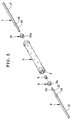
- a flash discharge tube 2 produced according to the present invention is illustrated.
- the flash discharge tube 2 includes a vessel 3, and a pin-shaped cathode 6 and a pin-shaped anode 7 as two electrodes.
- the vessel 3 is formed in a tubular shape, is transparent, and is made of glass. Openings 4 and 5 are formed in ends of the vessel 3.
- the pin-shaped cathode and anode 6 and 7 are inserted in respectively the openings 4 and 5.
- a ring-shaped cathode part 8 is attached to the pin-shaped cathode 6. Glass beads 9 and 10 are fitted in the openings 4 and 5 in a tight manner.
- Xenon gas as inert gas is filled in the vessel 3.
- the pin-shaped cathode 6 includes a cathode core 12 as electrode core, and a lead 13.
- the cathode core 12 is contained in the vessel 3.
- the lead 13 protrudes externally from the vessel 3, and is used for wiring to a printed circuit board.
- a ball-shaped melted portion 14 is formed by welding between the cathode core 12 and the lead 13.
- the cathode core 12 is formed from tungsten (W) in a bar shape.
- a recess or groove 20 is formed in the cathode core 12 for attaching the ring-shaped cathode part 8.
- the lead 13 is formed from nickel (Ni), and has a diameter equal to or greater than a diameter of the cathode core 12.
- the ball-shaped melted portion 14 is formed by partially melting the lead 13 to cover an end of the cathode core 12 because of welding between the cathode core 12 and the lead 13.
- the cathode core 12 may be formed materials other than tungsten. Examples of materials for the cathode core 12 are alloy of nickel cobalt and iron, alloy of nickel and iron, and alloy of molybdenum.
- the lead 13 may be formed materials other than nickel. Examples of materials for the lead 13 are manganese-nickel (Mn-Ni), alloy of cobalt, nickel and iron, alloy of nickel and iron, and alloy of molybdenum.
- the pin-shaped anode 7 includes an anode core 16 as electrode core, a lead 17, and a ball-shaped melted portion 18 all similar to the pin-shaped cathode 6.
- the anode core 16 has a length different from that of the cathode core 12. Except for this, the pin-shaped anode 7 is produced from the same material and in the same manner as the pin-shaped cathode 6.
- the glass beads 9 and 10 are formed in a ring shape. Holes 9a and 10a are formed in the glass beads 9 and 10 for insertion of the cathode core 12 and the anode core 16 of the pin-shaped cathode and anode 6 and 7.
- the glass beads 9 and 10, after insertion of the cathode core 12 and the anode core 16, are heated by a heater, and welded on to the cathode core 12 and the anode core 16. Then the glass beads 9 and 10 are inserted in the openings 4 and 5 of the vessel 3, heated and melted by a heater, to close and seal the vessel 3 tightly.
- the ring-shaped cathode part 8 includes components of metal and a cesium compound. At first, powder of the metal is formed in a ring shape, and sintered. The cesium compound is added to this, and processed. In operation, the ring-shaped cathode part 8 keeps efficiency high in emitting electron during electric discharge. To fix the ring-shaped cathode part 8, the ring-shaped cathode part 8 is positioned at the recess 20 of the cathode core 12, and then depressed and deformed by caulking for tight attachment.
- a line for producing the pin-shaped cathode 6 is schematically illustrated.
- the producing line is constituted by a welding process and a recess forming process.
- a tungsten bar 22 as the cathode core 12 is welded on to a nickel bar 23 as the lead 13, to obtain the pin-shaped cathode 6.
- the recess forming process the recess 20 is formed in the cathode core 12 of the pin-shaped cathode 6.
- the line includes an indexing table 24, and first, second, third, fourth, fifth, sixth, seventh and eighth stations 25, 26, 27, 28, 29, 30, 31 and 32.
- the indexing table 24 rotates stepwise by a unit angle of 45 degrees.
- the eight stations 25-32 are disposed where each pallet in the indexing table 24 is stopped.
- Various devices are disposed in the eight stations 25-32.
- Each of the chuck mechanisms 34 includes two jaws or arms 35, and a shifter for moving the jaws 35 between a first position for squeezing the tungsten bar 22 and a second position for releasing the tungsten bar 22.
- grooves or recesses are formed in contact walls of the jaws 35, have shapes for being fitted on the outer surface of the tungsten bar 22.
- the recesses make it possible to squeeze the tungsten bar 22 with high precision.
- Examples of the shifter are a solenoid, cam mechanism and the like.
- the chuck mechanisms 34 squeeze with such force that the tungsten bar 22 does not offset in the axial direction, and that no flaw or defect will remain in the tungsten bar 22 being captured.
- Each of the chuck mechanisms 37 includes two jaws or arms 38, and a shifter for moving the jaws 38 between a first position for squeezing the nickel bar 23 and a second position for releasing the nickel bar 23.
- Grooves or recesses are formed in contact walls of the jaws 38, have shapes for being fitted on the outer surface of the nickel bar 23. The recesses make it possible to squeeze the nickel bar 23 with high precision.
- Examples of the shifter are a solenoid, cam mechanism and the like.
- the chuck mechanisms 37 squeeze with such force that the nickel bar 23 does not offset in the axial direction, and that no flaw or defect will remain in the nickel bar 23 being captured.
- the jaws 35 of the chuck mechanism 34 are movable in a squeezing direction being perpendicular to that in which the jaws 38 of the chuck mechanisms 37 are movable.
- This is advantageous because the shifters for the chuck mechanisms 34 and 37 can be disposed away from one another, so as to reduce an overall size of the indexing table 24.
- precision in the concentricity between the tungsten bar 22 and the nickel bar 23 can be high.
- the chuck mechanisms 34 and 37 constitute welding electrodes, included in a resistance welding device, for connection with the tungsten bar 22 and the nickel bar 23 being squeezed.
- the materials for the chuck mechanisms 34 and 37 include chromium copper (Cu-Cr), tungsten copper (Cu-W), superhard material and the like, and a combination of at least two of those, for the purpose of good electrical conductivity.
- a tungsten bar supply device 40 is disposed in the first station 25 on the periphery of the indexing table 24, and includes a part feeder, and a pick-&-placement mechanism or picking mechanism.
- the part feeder aligns the tungsten bar 22 produced by a separate manufacturing line.
- the pick-&-placement mechanism picks the tungsten bar 22 from the part feeder individually, and sends the tungsten bar 22 to a space between the jaws 35 of the chuck mechanism 34.
- a protrusion adjusting device 42 is disposed at the second station 26, for adjusting a length Ls at which the tungsten bar 22 protrudes from an end of the chuck mechanism 34.
- the length Ls is predetermined and stored.
- the tungsten bar supply device 40 causes the chuck mechanism 34 in such a manner that the tungsten bar 22 protrudes from the chuck mechanism 34 at a protruding amount sufficiently greater than the length Ls. Then the protrusion adjusting device 42 is controlled to slide the tungsten bar 22 in a direction toward the inside of the chuck mechanism 34, to reduce the protruding amount to the length Ls.
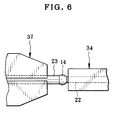
- a nickel bar supply device 44 is disposed in the third station 27. At first, nickel wire with a continuous length and a constant width is produced, wound about a reel, and set in the nickel bar supply device 44. The nickel bar supply device 44 draws the nickel wire from the reel, and uncurls the nickel wire by use of a frictional roller or the like. Then the nickel wire is wiped with solvent and non-woven cloth or other fibrous wiping material, to remove dust, powdery dirt, oil component and the like. After this, the nickel bar 23 is produced by cutting the nickel wire at a predetermined length. The nickel bar 23 is obtained, is transferred to the chuck mechanism 37 by a pick-&-placement mechanism, and is squeezed by the jaws 38. In Fig. 5A, ends of the tungsten bar 22 and the nickel bar 23 are opposed to one another.
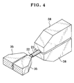
- a butting device 46 is disposed at the fourth station 28, and operates to shift the chuck mechanism 37 toward the chuck mechanism 34.
- an end of the nickel bar 23 is advanced to butt on an end of the tungsten bar 22.
- a spring is incorporated in the butting device 46, and exerts normally constant force to press the nickel bar 23 against the tungsten bar 22.
- a resistance welding device 49 is disposed at the fifth station 29.
- the resistance welding device 49 causes a current to flow between the chuck mechanisms 34 and 37.
- the tungsten bar 22 and the nickel bar 23 are heated because of the current and pressure.
- the end of the nickel bar 23 is melted to wrap an end of the tungsten bar 22 so as to weld the tungsten bar 22 and the nickel bar 23 to each other.
- the current flows in a direction from the chuck mechanism 34 to the chuck mechanism 37 for the purpose of generating heat according to the Peltier effect.
- the nickel bar 23 is released from being squeezed in the chuck mechanism 37.
- the chuck mechanism 37 comes away from the chuck mechanism 34.
- a pick-&-placement device 51 is disposed, for receiving the pin-shaped cathode 6 from the chuck mechanism 34, to supply the pin-shaped cathode 6 to a station for the recess forming process. Note that, if an alarm signal is generated in the resistance welding device 49 or other devices at the time of the welding, the pin-shaped cathode 6 is fed to the eighth station 32 without moving to a region for the recess forming process. In the eighth station 32, the chuck mechanism 34 is opened to eliminate the pin-shaped cathode 6 determined unacceptable, for collection of failing electrodes.
- the indexing table 54 has a smaller diameter than that of the indexing table 24, and rotates stepwise by a unit angle of 60 degrees.
- the six stations 55-60 are disposed where each pallet in the indexing table 54 is stopped.
- the electrode chucks 62 include a pair of jaws or arms, and a shifter.
- the jaws squeeze the lead 13.
- the shifter moves the jaws between a first position for grasping the lead 13 and a second position for releasing the lead 13.
- An example of the shifter includes a solenoid, cam mechanism or the like.
- the pick-&-placement device 51 supplies the pin-shaped cathode 6 from the seventh station 31 of the welding process.
- the pin-shaped cathode 6 is squeezed by the electrode chuck 62.
- An electrode positioning device 64 is disposed at the second station 56, and adjusts a position of the pin-shaped cathode 6 nipped by the electrode chuck 62.
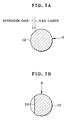
- the laser processing device 66 consists of a laser system of YAG (yttrium aluminum garnet) laser, and as illustrated in Fig. 7A, emits laser light toward the cathode core 12 of the pin-shaped cathode 6, so as to form the recess 20. See Fig. 7B.
- the gas ejecting device 67 ejects nitrogen gas toward the pin-shaped cathode 6 while the laser light forms the recess 20, to blow away dust of melted tungsten from the pin-shaped cathode 6 to eliminate residual dust therefrom.
- a shape inspecting device 69 is disposed at the fourth station 58.
- the shape inspecting device 69 includes a video camera unit and a control unit.
- the video camera unit picks up an image of the pin-shaped cathode 6 to obtain image data.
- the control unit stores reference data, compares the image data from the video camera unit with the reference data, to determine a size of the recess 20, or acceptability of a shape of the recess 20.
- the electrode chuck 62 is opened, from which the pin-shaped cathode 6 is unloaded.
- a product receptacle or container 71 is disposed at the fifth station 59, and receives the pin-shaped cathode 6, and transfers the same to a succeeding line for producing a flash discharge tube. If the pin-shaped cathode 6 is determined unacceptable in the shape inspecting device 69 at the fourth station 58, the pin-shaped cathode 6 moves past the fifth station 59 without unloading from the electrode chuck 62. When the pin-shaped cathode 6 reaches the sixth station 60, the pin-shaped cathode 6 is removed from the electrode chuck 62 at the sixth station 60.
- An failure product receptacle or container 72 at the sixth station 60 receives the pin-shaped cathode 6, and collects electrodes created one after another.
- a producing line for the pin-shaped anode 7 is the same as that for the pin-shaped cathode 6 except for lack of partial elements including the seventh station 31 and the recess forming process.
- the pin-shaped cathode 6 and the pin-shaped anode 7 are transferred to a line for producing a flash discharge tube.
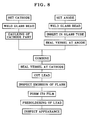
- a flow of steps is illustrated, according to which the producing line produces the flash discharge tube.
- a heating support plate 75 or heater jig is illustrated, and includes hundreds of retention holes 76.
- the pin-shaped cathode 6 supplied to the producing line is inserted into each of the retention holes 76 by advancing the lead 13.
- the heating support plate 75 has a plate shape, is formed from carbon, and includes the retention holes 76 aligned regularly. The hundreds of the pin-shaped cathodes 6 are treated at the same time in the heating support plate 75.
- the glass bead 9 is supplied so that the cathode core 12 of the pin-shaped cathode 6 is inserted in the glass bead 9.
- the pin-shaped cathode 6, the glass bead 9 together with the heating support plate 75 are supplied with heat by a heater. Therefore, the glass bead 9 is melted and welded on to the pin-shaped cathode 6.
- Fig. 9B the cathode core 12 of the pin-shaped cathode 6 is inserted in the ring-shaped cathode part 8, which is depressed and deformed according to a technique of caulking, and is attached fixedly to the pin-shaped cathode 6.
- An example of the caulking method and device used herein is disclosed in JP-A 6-230456.
- the pin-shaped anode 7 is set on the heating support plate 75.
- the glass bead 10 is melted and welded.
- the vessel 3 is supplied to the pin-shaped anode 7, receives insertion of the pin-shaped anode 7, and is heated by the heater again.
- the glass bead 10 and the vessel 3 are melted and welded together, to fix the pin-shaped anode 7 on the vessel 3.
- the pin-shaped cathode 6 is inserted in the vessel 3 supported in the heating support plate 75.
- the portion of the vessel 3 with the pin-shaped cathode 6 is held by the heating support plate 75, and is heated. See Fig. 10.
- the heat is applied in a condition filled with xenon gas.
- the vessel 3 is closed and sealed.
- xenon gas is enclosed in the flash discharge tube 2.
- the lead 13 of the pin-shaped cathode 6 and the lead 17 of the pin-shaped anode 7 are cut down at a predetermined length.
- the flash discharge tube is subjected to inspection of flash emission. If the flash discharge tube 2 is determined acceptable after the inspection, then the vessel 3 is coated with a film of ITO (indium tin oxide). Appearance of the flash discharge tube 2 is inspected, before the flash discharge tube 2 is shipped out.
- ITO indium tin oxide
- the cathode core 12 of the pin-shaped cathode 6 has a diameter Dw of 0.6 mm, and a length Lw of 4.5 mm.
- the lead 13 has a diameter Dn of 0.8 mm.
- the pin-shaped cathode 6 has a total length Ld of 19.5 mm.
- the ball-shaped melted portion 14 has a diameter Db of 0.95-1.13 mm, and a size Lb that is preferably 0.8 mm in the axial direction of the electrode.
- the pin-shaped anode 7 is different from the pin-shaped cathode 6 in that the anode core 16 has a length of 3.5 mm and the pin-shaped anode 7 has a total length of 18.5 mm. Except for those, the pin-shaped anode 7 has the same sizes as those of the pin-shaped cathode 6.
- the size Lb of the ball-shaped melted portion 14 is an important factor in view of maintaining quality of the flash discharge tube 2.
- the ball-shaped melted portion 14 is used for positioning the pin-shaped cathode 6 on the vessel 3. Should the size Lb be too great, the length Lw of the cathode core 12 will be too small. Should the size Lb be too small, the length Lw of the cathode core 12 will be too great. So a distance between the cathode core 12 and the anode core 16 is likely to be uneven. An arc length of the electric discharge may change.
- the ball-shaped melted portion 14 has a shape of an ellipsoid like a pumpkin fruit defined by compressing a sphere in one direction, in comparison with a shape of an ellipsoid like a rugby ball defined by extending a sphere in one direction.
- the ball-shaped melted portion 14 should meet the condition of Lb ⁇ Db instead of Lb > Db.
- a great number of electrodes 6 were produced in combination of the tungsten bar 22 and the nickel bar 23 by changing conditions of welding for obtaining optimum condition to manufacture the ball-shaped melted portion 14 regularly at the above described size.
- the shape of the ball-shaped melted portion 14 depended on various factors, that were the protruding amount Ls of the tungsten bar 22 from the end of the chuck mechanism 34, the force of the tungsten bar 22 to push the nickel bar 23, the voltage applied for the resistance welding, and the time of applying the voltage.
- the tungsten bar 22 and the nickel bar 23 were welded to one another in such a manner as to maintain the ball diameter Db at approximately 1 mm by changing the protruding amount Ls of the tungsten bar 22 and the voltage. Then the length Lw of the electrode, the ball diameter Db and the ball size Lb were measured, and indicated in the graph of Fig. 12. Note that ten samples of electrodes were produced experimentally for measurement. Values indicated in Fig. 12 were averages of the ten. In Fig. 13, a pattern of applying voltage is illustrated. The tungsten bar 22 and the nickel bar 23 were preheated at a preheating voltage level P3 for 40 msec, and heated at a heating voltage level P4 for 55 msec for a main process of welding by melting the nickel bar 23.
- the experiment was conducted with other samples.
- the protruding amount Ls of the tungsten bar 22 was uniquely determined 0.7 mm.
- the welding time was determined 10 msec and 75 msec.
- the length Lw of the electrode, the ball diameter Db and the ball size Lb were measured. Note that ten samples of electrodes were produced experimentally for measurement. Values indicated in Fig. 14 were averages of the ten. In Fig. 15, a pattern of applying voltage is illustrated.
- the tungsten bar 22 and the nickel bar 23 were heated at a heating voltage level P4 for T4 (msec) for a main welding by melting the nickel bar 23.
- the nickel bar 23 was melted only when the voltage P3 was set at nearly 1.5 volts or higher and when the welding time was 10 msec. When the welding time was 75 msec, the nickel bar 23 was melted when the voltage was as low as 0.7 volt. If the welding time is short, voltage to be applied must be set high. In the experiment in which the voltage was high, portions of the tungsten bar 22 and the nickel bar 23 different from the butting portions was heated remarkably to cause the ball-shaped melted portion 14 to have a shape of an ellipsoid like a rugby ball defined by extending a sphere in one direction.
- the ball-shaped melted portion 14 came to have a shape of an ellipsoid like a pumpkin fruit defined by compressing a sphere in one direction.
- problems are likely to occur because of oxidization and eccentricity in the pushing direction. This being so, it was found that a preferable value of the welding time was nearly 50 msec. Note that a preferable condition of welding was the same in the case of the pin-shaped anode 7.
- the laser processing device 66 and the gas ejecting device 67 were operated in the conditions as follows: Laser output energy 14.7 J Pulse width 1 msec Beam diameter 0.6 mm Peak of output 3.8 kw Focal length 55 mm Gas flow rate 30 liters per minute
- a comparative example according to the prior art is referred to as Sample No. 3.
- the ring-shaped cathode part 8 was attached by caulking, and was subjected to measurement of force required for pulling away. Results of those were obtained, and are indicated in Table 1. Samples No. 1 No. 2 No. 3 No. Of Electrodes 13 17 10 Average Force (kgf) For Being Drawn Away 1.28 1.35 1.41 Maximum Force (kgf) For Being Drawn Away 1.85 1.70 2.00 Minimum Force (kgf) For Being Drawn Away 0.74 0.91 0.85
- the force required for drawing away the ring-shaped cathode part 8 should be 1 kgf or higher at an average level, and at least 0.5 kgf or higher, for the purpose of tight attachment.
- the average force required for drawing away the ring-shaped cathode part 8 was 1 kgf or higher at the average, and at least 0.5 kgf or higher after forming the recess with laser. According to the above results, it was found that conditions of Lm and Dm indicated below could be satisfied by forming the recess.
- Lc is a size of the ring-shaped cathode part 8 in the axial direction. See Fig. 18. 0.1 Lc ⁇ Lm ⁇ 0.8 Lc 0.03 Dw ⁇ Dm ⁇ 0.4 Dw
- the recess 20 or the double recess 80 can have any one of elliptical, oval, quadrilateral shapes or the like.
- the number of unit gaps in the recess 20 or the double recess 80 may be in a range of 1-6 for the purpose of raising the force required for drawing away.
- the recess 20 is formed in the pin-shaped cathode 6 to tighten the attachment of the ring-shaped cathode part 8. Furthermore, the pin-shaped cathode 6 can be subjected to sandblast finish and provided with surface roughness (in ⁇ m) for the same purpose. Table 2 indicates surface roughness obtained by sandblast finish of the tungsten bar 22 by use of shots having shot diameters of #46 and #60. Note that the sandblast method included steps of setting a plurality of the tungsten bars 22 in a colander, net, basket or a suitable receptacle, rotating the receptacle at a low rotational speed, and blowing the shots to the tungsten bars 22 at a prescribed pressure of air.
- the sandblast finish is additionally effective in facilitating the welding, because all the surface of the tungsten bar 22 including its end faces are roughened. It is also possible to subject the sandblast method to the pin-shaped cathode 6 after the tungsten bar 22 is welded to the nickel bar 23. This is additionally effective, because the sandblast method can remove surplus nickel flash created on a surface of the melted ball at the time of welding.
- the electrode core 12, 16, 22 has a diameter Dw
- the protruding amount Ls of the electrode core 12, 16, 22 from the first chuck mechanism 34 is from 0.8 ⁇ Dw to 1.5 ⁇ Dw.
- the protruding amount Ls of the electrode core 12, 16, 22 from the first chuck mechanism 34 can be from 0.6 ⁇ Dw to 1.5 ⁇ Dw.
- the cathode part 8 has a size- Lc in an axial direction
- the recess 20, 80 has a width Lm from 0.1 ⁇ Lc to 0.8 ⁇ Lc in the axial direction.
- the recess 20, 80 can have a width Lm from 0.1 ⁇ Lc to 1.5 ⁇ Lc in the axial direction.
Landscapes
- Engineering & Computer Science (AREA)
- Manufacturing & Machinery (AREA)
- Mechanical Engineering (AREA)
- Discharge Lamp (AREA)
- Manufacture Of Electron Tubes, Discharge Lamp Vessels, Lead-In Wires, And The Like (AREA)
Priority Applications (1)
| Application Number | Priority Date | Filing Date | Title |
|---|---|---|---|
| EP06007583A EP1701371A1 (de) | 2001-07-04 | 2002-07-02 | Verfahren zur Herstellung von Elektroden |
Applications Claiming Priority (2)
| Application Number | Priority Date | Filing Date | Title |
|---|---|---|---|
| JP2001203864 | 2001-07-04 | ||
| JP2001203864 | 2001-07-04 |
Related Child Applications (1)
| Application Number | Title | Priority Date | Filing Date |
|---|---|---|---|
| EP06007583A Division EP1701371A1 (de) | 2001-07-04 | 2002-07-02 | Verfahren zur Herstellung von Elektroden |
Publications (2)
| Publication Number | Publication Date |
|---|---|
| EP1273379A2 true EP1273379A2 (de) | 2003-01-08 |
| EP1273379A3 EP1273379A3 (de) | 2006-07-12 |
Family
ID=19040427
Family Applications (2)
| Application Number | Title | Priority Date | Filing Date |
|---|---|---|---|
| EP02014639A Withdrawn EP1273379A3 (de) | 2001-07-04 | 2002-07-02 | Verfahren zur Herstellung von Elektroden |
| EP06007583A Withdrawn EP1701371A1 (de) | 2001-07-04 | 2002-07-02 | Verfahren zur Herstellung von Elektroden |
Family Applications After (1)
| Application Number | Title | Priority Date | Filing Date |
|---|---|---|---|
| EP06007583A Withdrawn EP1701371A1 (de) | 2001-07-04 | 2002-07-02 | Verfahren zur Herstellung von Elektroden |
Country Status (3)
| Country | Link |
|---|---|
| US (1) | US6800011B2 (de) |
| EP (2) | EP1273379A3 (de) |
| CN (1) | CN1395273A (de) |
Cited By (1)
| Publication number | Priority date | Publication date | Assignee | Title |
|---|---|---|---|---|
| WO2007122535A3 (en) * | 2006-04-21 | 2008-05-22 | Koninkl Philips Electronics Nv | A method of manufacturing tungsten electrode rods |
Families Citing this family (3)
| Publication number | Priority date | Publication date | Assignee | Title |
|---|---|---|---|---|
| CN1306541C (zh) * | 2004-01-08 | 2007-03-21 | 彩虹集团电子股份有限公司 | 一种电子枪制造用三节导丝的制备工艺 |
| US7404496B2 (en) * | 2005-06-20 | 2008-07-29 | Osram Sylvania Inc. | Green-state ceramic discharge vessel parts |
| CN116364529B (zh) * | 2023-02-16 | 2024-11-12 | 国开启科量子技术(北京)有限公司 | 用于制备离子阱针形电极的方法 |
Family Cites Families (16)
| Publication number | Priority date | Publication date | Assignee | Title |
|---|---|---|---|---|
| US3259969A (en) * | 1963-01-22 | 1966-07-12 | Central Cable Corp | Method of making butt welded joints |
| US3521107A (en) * | 1968-08-26 | 1970-07-21 | Gen Electric | Flashtube getter electrode |
| US4275329A (en) * | 1978-12-29 | 1981-06-23 | General Electric Company | Electrode with overwind for miniature metal vapor lamp |
| JPS63308858A (ja) * | 1987-06-11 | 1988-12-16 | Toshiba Corp | ショ−トア−ク放電灯 |
| HU200031B (en) * | 1988-03-28 | 1990-03-28 | Tungsram Reszvenytarsasag | High-pressure discharge lamp |
| US5606219A (en) * | 1992-12-25 | 1997-02-25 | Fuji Photo Film Co., Ltd. | Cathode for electronic flash tube |
| JP3364504B2 (ja) | 1993-02-05 | 2003-01-08 | 富士写真フイルム株式会社 | 閃光放電管の陰極材固着方法 |
| BE1007713A3 (nl) * | 1993-11-09 | 1995-10-03 | Philips Electronics Nv | Elektrische lamp. |
| JPH07226185A (ja) * | 1994-02-09 | 1995-08-22 | Toho Kinzoku Kk | 管球用タングステン棒 |
| US5645930A (en) * | 1995-08-11 | 1997-07-08 | The Dow Chemical Company | Durable electrode coatings |
| US5880559A (en) * | 1996-06-01 | 1999-03-09 | Smiths Industries Public Limited Company | Electrodes and lamps |
| DE19631188A1 (de) * | 1996-08-02 | 1998-02-05 | Heraeus Kulzer Gmbh | Entladungslampenanordnung |
| US5880425A (en) * | 1997-04-29 | 1999-03-09 | Board Of Regents, The University Of Texas System | Method and apparatus for joining metals |
| US6268697B1 (en) * | 1997-12-16 | 2001-07-31 | Fuji Photo Film Co., Ltd. | Flash discharge tube having exterior trigger electrode |
| DE19757152C2 (de) * | 1997-12-20 | 2002-10-31 | Thomas Eggers | Elektrode für Entladungslampen |
| DE19808981A1 (de) * | 1998-03-04 | 1999-09-09 | Patent Treuhand Ges Fuer Elektrische Gluehlampen Mbh | Elektrode mit Wendelaufsatz |
-
2002
- 2002-07-02 EP EP02014639A patent/EP1273379A3/de not_active Withdrawn
- 2002-07-02 EP EP06007583A patent/EP1701371A1/de not_active Withdrawn
- 2002-07-03 US US10/188,361 patent/US6800011B2/en not_active Expired - Fee Related
- 2002-07-04 CN CN02140297.3A patent/CN1395273A/zh active Pending
Cited By (1)
| Publication number | Priority date | Publication date | Assignee | Title |
|---|---|---|---|---|
| WO2007122535A3 (en) * | 2006-04-21 | 2008-05-22 | Koninkl Philips Electronics Nv | A method of manufacturing tungsten electrode rods |
Also Published As
| Publication number | Publication date |
|---|---|
| US6800011B2 (en) | 2004-10-05 |
| EP1701371A1 (de) | 2006-09-13 |
| US20030087578A1 (en) | 2003-05-08 |
| CN1395273A (zh) | 2003-02-05 |
| EP1273379A3 (de) | 2006-07-12 |
Similar Documents
| Publication | Publication Date | Title |
|---|---|---|
| EP1586402A1 (de) | Lötkolbenspitze, herstellungsverfahren dafür, elektrischer lötkolben und elektrischer entlötkolben mit der kolbenspitze | |
| US6800011B2 (en) | Electrode producing method | |
| JP4856788B2 (ja) | 放電ランプ用電極、高圧放電ランプ、ランプユニットおよび投射型画像表示装置 | |
| KR102684664B1 (ko) | 범프 형성 장치, 범프 형성 방법, 땜납 볼 리페어 장치, 및, 땜납 볼 리페어 방법 | |
| US6554670B1 (en) | Method for capping lamps | |
| US6604973B2 (en) | Flash discharge tube and method for producing the same | |
| US5128584A (en) | Impregnated cathode | |
| JP2003086092A (ja) | ストロボ放電管の電極棒製造方法 | |
| US6437509B1 (en) | Electrode for discharge lamps | |
| EP0604951B1 (de) | Elektronenkanone für eine Kathodenstrahlröhre | |
| US20040140293A1 (en) | Method and device for connecting minute joint metal, and composite tape for connecting minute joint metal | |
| EP1056111B1 (de) | Herstellungsverfahren von Lampen | |
| WO2004048025A1 (en) | Air-cooling type torch using magnetic force | |
| JP2683292B2 (ja) | 放電灯用電極及び電極の加工方法 | |
| US10804681B2 (en) | Method for manufacturing a spark plug that makes welded portions uniform | |
| US20190143726A1 (en) | Aluminum Based Solderable Contact | |
| JP7715431B2 (ja) | 蓄電デバイス用リード端子の製造方法 | |
| CN1166686A (zh) | 直热式阴极结构 | |
| JP2003178668A (ja) | 管球用導入線および管球 | |
| US7462991B2 (en) | Fluorescent lamp cathode and method of making cathodes | |
| JPS6336606Y2 (de) | ||
| GB1583585A (en) | Dispenser cathode | |
| JP2001256930A (ja) | 管球の製造方法 | |
| JPH10289657A (ja) | キセノン放電管の製造方法 | |
| JPH0750130A (ja) | 陰極線管の製造方法 |
Legal Events
| Date | Code | Title | Description |
|---|---|---|---|
| PUAI | Public reference made under article 153(3) epc to a published international application that has entered the european phase |
Free format text: ORIGINAL CODE: 0009012 |
|
| AK | Designated contracting states |
Kind code of ref document: A2 Designated state(s): AT BE BG CH CY CZ DE DK EE ES FI FR GB GR IE IT LI LU MC NL PT SE SK TR |
|
| AX | Request for extension of the european patent |
Free format text: AL;LT;LV;MK;RO;SI |
|
| PUAL | Search report despatched |
Free format text: ORIGINAL CODE: 0009013 |
|
| AK | Designated contracting states |
Kind code of ref document: A3 Designated state(s): AT BE BG CH CY CZ DE DK EE ES FI FR GB GR IE IT LI LU MC NL PT SE SK TR |
|
| AX | Request for extension of the european patent |
Extension state: AL LT LV MK RO SI |
|
| 17P | Request for examination filed |
Effective date: 20060901 |
|
| RAP1 | Party data changed (applicant data changed or rights of an application transferred) |
Owner name: FUJIFILM CORPORATION |
|
| AKX | Designation fees paid |
Designated state(s): DE FR GB NL |
|
| 17Q | First examination report despatched |
Effective date: 20070508 |
|
| GRAP | Despatch of communication of intention to grant a patent |
Free format text: ORIGINAL CODE: EPIDOSNIGR1 |
|
| STAA | Information on the status of an ep patent application or granted ep patent |
Free format text: STATUS: THE APPLICATION IS DEEMED TO BE WITHDRAWN |
|
| 18D | Application deemed to be withdrawn |
Effective date: 20110201 |