EP1273394A2 - Outil pour échanger des têtes de coupe remplaçables - Google Patents
Outil pour échanger des têtes de coupe remplaçables Download PDFInfo
- Publication number
- EP1273394A2 EP1273394A2 EP02445073A EP02445073A EP1273394A2 EP 1273394 A2 EP1273394 A2 EP 1273394A2 EP 02445073 A EP02445073 A EP 02445073A EP 02445073 A EP02445073 A EP 02445073A EP 1273394 A2 EP1273394 A2 EP 1273394A2
- Authority
- EP
- European Patent Office
- Prior art keywords
- tool
- cutting head
- tool according
- replaceable cutting
- free end
- Prior art date
- Legal status (The legal status is an assumption and is not a legal conclusion. Google has not performed a legal analysis and makes no representation as to the accuracy of the status listed.)
- Withdrawn
Links
Images
Classifications
-
- B—PERFORMING OPERATIONS; TRANSPORTING
- B23—MACHINE TOOLS; METAL-WORKING NOT OTHERWISE PROVIDED FOR
- B23Q—DETAILS, COMPONENTS, OR ACCESSORIES FOR MACHINE TOOLS, e.g. ARRANGEMENTS FOR COPYING OR CONTROLLING; MACHINE TOOLS IN GENERAL CHARACTERISED BY THE CONSTRUCTION OF PARTICULAR DETAILS OR COMPONENTS; COMBINATIONS OR ASSOCIATIONS OF METAL-WORKING MACHINES, NOT DIRECTED TO A PARTICULAR RESULT
- B23Q11/00—Accessories fitted to machine tools for keeping tools or parts of the machine in good working condition or for cooling work; Safety devices specially combined with or arranged in, or specially adapted for use in connection with, machine tools
-
- B—PERFORMING OPERATIONS; TRANSPORTING
- B25—HAND TOOLS; PORTABLE POWER-DRIVEN TOOLS; MANIPULATORS
- B25B—TOOLS OR BENCH DEVICES NOT OTHERWISE PROVIDED FOR, FOR FASTENING, CONNECTING, DISENGAGING, OR HOLDING
- B25B9/00—Hand-held gripping tools other than those covered by group B25B7/00
-
- B—PERFORMING OPERATIONS; TRANSPORTING
- B25—HAND TOOLS; PORTABLE POWER-DRIVEN TOOLS; MANIPULATORS
- B25B—TOOLS OR BENCH DEVICES NOT OTHERWISE PROVIDED FOR, FOR FASTENING, CONNECTING, DISENGAGING, OR HOLDING
- B25B27/00—Hand tools, specially adapted for fitting together or separating parts or objects whether or not involving some deformation, not otherwise provided for
- B25B27/14—Hand tools, specially adapted for fitting together or separating parts or objects whether or not involving some deformation, not otherwise provided for for assembling objects other than by press fit or detaching same
-
- Y—GENERAL TAGGING OF NEW TECHNOLOGICAL DEVELOPMENTS; GENERAL TAGGING OF CROSS-SECTIONAL TECHNOLOGIES SPANNING OVER SEVERAL SECTIONS OF THE IPC; TECHNICAL SUBJECTS COVERED BY FORMER USPC CROSS-REFERENCE ART COLLECTIONS [XRACs] AND DIGESTS
- Y10—TECHNICAL SUBJECTS COVERED BY FORMER USPC
- Y10T—TECHNICAL SUBJECTS COVERED BY FORMER US CLASSIFICATION
- Y10T408/00—Cutting by use of rotating axially moving tool
- Y10T408/96—Miscellaneous
Definitions
- the present invention relates to a tool for changing a replaceable cutting head of a tool for chip removing machining
- a device for assembling and disassembling a tool unit for chip removing machining is previously known from US-A-5,957,631.
- This device has a cylindrical cavity with a diameter that equals the diameter of a replaceable cutting head included in the tool unit.
- convex portions are arranged that may be received in the chip channels of the replaceable cutting head.
- the device may also be provided with members that prevent the cutting head from falling out of the cavity when the same is fixed therein. The device is rotated by hand when the replaceable cutting head is to be assembled and disassembled.
- This device only fits a replaceable cutting head having a certain diameter and also in other respects, the cavity of the device and the replaceable cutting head are complementary.
- a primary aim of the present invention is to describe a tool of the kind defined in the introduction, which is exceptionally user-friendly due to the fact that the same may easily be adjusted to different diameters of the replaceable cutting head with which the tool is to co-operate.
- Another aim of the present invention is that the tool should be structurally simple, especially it should consist of few components, and thereby also be inexpensive to manufacture.
- Yet another aim of the present invention is that the design of the tool should be such that it is able to apply a relatively large torque to the replaceable cutting head.
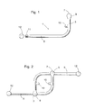
- the shank 1, illustrated in fig 1 is generally L-shaped and comprises a first part 3 and a second part 5, whereby the first the part 3 in the illustrated embodiment is shorter than the second part 5.
- the first part 3 is, at the free end thereof, provided with a thicker portion 7, which is penetrated by a hole 9 having an extension transverse to the extension of the first part 3 and is, in the main parallel to the extension of the second part 5.
- a shoulder 10 is arranged that has an extension in the direction of the free end of the second part 5.
- the second part 5 has an external threaded part 11 that is intended to receive an internally threaded hole of a knob 12, which is also included in the tool according to the present invention.
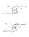
- the tool according to the present invention illustrated in fig 2 comprises two, preferably identical, shanks 1, whereby they are mounted in each other by the fact that the second part 5 of one of the shanks 1 is received in the hole 9 of the other shank 1.
- the knobs 12 are applied on the free ends of the second parts 5 thanks to the knobs 12 being threaded on the externally threaded portions 11.
- the distance between the shoulders 10 directed towards each other may be varied by a displacement of the thicker portions 7/the holes 9 taking place in relation to the appurtenant second part 5.
- the diameter of the holes 9 relates to the diameter of the second parts 5 in such a way that a slide fit is formed between the second parts 5 and the holes 9. At a maximum distance between the shoulders 10, the thicker parts 7 will abut against the knobs 12.
- the tool is removed by distancing the shoulders 10 from each other. This may easily be carried out since the friction between the second part 5 and the hole 9 is formed only when the parts 5 apply forces in order to rotate the replaceable cutting head.
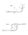
- fig 4 use of the tool according to the present invention is shown on a drill having a substantially smaller diameter than the drill in fig 3.
- an adaptation to the diameter of the replaceable cutting head S2 of the drill is easily carried out by the shoulders 10 being pushed towards each other until they are brought into engagement with the replaceable cutting head S2 and more precisely until they are brought into engagement with a chip channel or some other groove.
- Disassembly of the tool according to the present invention in relation to the cutting head S2 is carried out by distancing the shoulders 10 from each other.
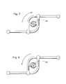
- the alternative design of a shank 101 differs from the shank 1 in the main by the design of the shoulder 110. For that reason, other parts of the shank 101 have been given the same reference designations as for the shank 1.
- the shoulder 110 has a part with a larger bending radius and a part with a smaller bending radius, whereby the parts continuously transform into each other.
- FIG. 7 How the tool according to Fig 6 is used with a drill having a relatively small diameter when the replaceable cutting head S3 is to be assembled is shown in fig 7.
- the portions of the shoulders 110 having a large bending radius are brought to co-operate with, for instance, the chip channels of the replaceable cutting head S3.
- the two embodiments described above exemplify two designs of the shoulders 10, 110.
- the design of the shoulders may be additionally varied within the scope of the invention, but it is important that a satisfactory co-operation between the shoulders and grooves of a replaceable cutting head is achieved both at tightening and loosening of the replaceable cutting head.
Landscapes
- Engineering & Computer Science (AREA)
- Mechanical Engineering (AREA)
- Milling Processes (AREA)
- Drilling Tools (AREA)
- Cutting Tools, Boring Holders, And Turrets (AREA)
- Knives (AREA)
Applications Claiming Priority (2)
| Application Number | Priority Date | Filing Date | Title |
|---|---|---|---|
| SE0102368 | 2001-07-03 | ||
| SE0102368A SE519532C2 (sv) | 2001-07-03 | 2001-07-03 | Verktyg för att byta en utbytbar skärspets |
Publications (2)
| Publication Number | Publication Date |
|---|---|
| EP1273394A2 true EP1273394A2 (fr) | 2003-01-08 |
| EP1273394A3 EP1273394A3 (fr) | 2005-09-07 |
Family
ID=20284712
Family Applications (1)
| Application Number | Title | Priority Date | Filing Date |
|---|---|---|---|
| EP02445073A Withdrawn EP1273394A3 (fr) | 2001-07-03 | 2002-06-05 | Outil pour échanger des têtes de coupe remplaçables |
Country Status (6)
| Country | Link |
|---|---|
| US (1) | US6792834B2 (fr) |
| EP (1) | EP1273394A3 (fr) |
| JP (1) | JP2003025242A (fr) |
| KR (1) | KR20030004107A (fr) |
| CN (1) | CN1239285C (fr) |
| SE (1) | SE519532C2 (fr) |
Families Citing this family (5)
| Publication number | Priority date | Publication date | Assignee | Title |
|---|---|---|---|---|
| US20110271802A1 (en) * | 2010-05-04 | 2011-11-10 | Edward Honig | Double handle tool |
| US8925427B2 (en) * | 2012-11-16 | 2015-01-06 | Scott York | Cat 40 tool holder wrench |
| US9032846B2 (en) * | 2012-11-16 | 2015-05-19 | Scott York | Milling tool holder wrench |
| CN103659641A (zh) * | 2013-11-30 | 2014-03-26 | 南通环球光学仪器有限公司 | 一种简易镜片夹具及其使用方法 |
| FR3035809A1 (fr) * | 2015-05-06 | 2016-11-11 | Happy Christian Rodrigue Nouje | La cle de la couronne (la tete diamantee du tube en acier de la carotteuse) |
Family Cites Families (8)
| Publication number | Priority date | Publication date | Assignee | Title |
|---|---|---|---|---|
| US790853A (en) * | 1903-04-11 | 1905-05-23 | James F Reddy | Flange-wrench. |
| US1384705A (en) * | 1920-08-09 | 1921-07-12 | Meyer William | Deck-plate key |
| US1579992A (en) * | 1924-11-24 | 1926-04-06 | Altman Alexander | Wrench |
| DE1831197U (de) * | 1960-12-16 | 1961-05-10 | Savarin & Veuve Foinant Sa | Hakenschluessel, insbesondere mit runden stiften. |
| US4718317A (en) * | 1986-08-21 | 1988-01-12 | Roy F. Hensler | Hose coupling wrench |
| US4819523A (en) * | 1987-04-27 | 1989-04-11 | Souza Alejandro Y | Lug nut wrench |
| IL120948A0 (en) * | 1997-05-29 | 1997-09-30 | Iscar Ltd | Cutting tool assembly |
| US6076435A (en) * | 1997-10-09 | 2000-06-20 | White, Sr.; Andrew C. | Tool for multiple purposes |
-
2001
- 2001-07-03 SE SE0102368A patent/SE519532C2/sv not_active IP Right Cessation
-
2002
- 2002-06-05 EP EP02445073A patent/EP1273394A3/fr not_active Withdrawn
- 2002-06-19 US US10/173,735 patent/US6792834B2/en not_active Expired - Fee Related
- 2002-06-27 CN CNB021244588A patent/CN1239285C/zh not_active Expired - Fee Related
- 2002-07-02 KR KR1020020037838A patent/KR20030004107A/ko not_active Withdrawn
- 2002-07-02 JP JP2002193305A patent/JP2003025242A/ja active Pending
Also Published As
| Publication number | Publication date |
|---|---|
| EP1273394A3 (fr) | 2005-09-07 |
| CN1239285C (zh) | 2006-02-01 |
| KR20030004107A (ko) | 2003-01-14 |
| US6792834B2 (en) | 2004-09-21 |
| CN1394710A (zh) | 2003-02-05 |
| SE519532C2 (sv) | 2003-03-11 |
| SE0102368L (sv) | 2003-01-04 |
| SE0102368D0 (sv) | 2001-07-03 |
| JP2003025242A (ja) | 2003-01-29 |
| US20030007842A1 (en) | 2003-01-09 |
Similar Documents
| Publication | Publication Date | Title |
|---|---|---|
| US5435672A (en) | Hole saw having plug ejection feature | |
| EP1753575B1 (fr) | Ensemble de scie-cloche | |
| US6095736A (en) | Self-contained fastener device | |
| EP1358409B1 (fr) | Mecanisme de verrouillage active par levier destine a une tige telescopique | |
| AU724736B2 (en) | Tool-less machine tool chuck | |
| US5417527A (en) | Quick change chuck assembly for tool bits | |
| US6161982A (en) | Assembly with a sealed coupler | |
| CA2493219C (fr) | Mecanisme de mandrin a connexion rapide | |
| US4102375A (en) | Variable-length tool holder | |
| US20020122703A1 (en) | Quick change adaptor for hole saw | |
| KR20040045628A (ko) | 뼈 고정장치와 조립방법 및 시술 공구 | |
| CA2560173A1 (fr) | Tournevis d'extraction | |
| WO2001019571A1 (fr) | Dispositif permettant de limiter le couple a usage chirurgical | |
| AU2007327556A1 (en) | A hole saw assembly including drive shafts supported by a rotatable annulus | |
| US6880832B2 (en) | Quick change power tool chuck | |
| GB2257381A (en) | Arbor for hole saw. | |
| WO2004011179A1 (fr) | Arbre de scie trepan | |
| US20110121522A1 (en) | Quick change power tool chuck | |
| US11446068B2 (en) | Driven universal screw guide | |
| US5190422A (en) | Device for the quick fastening of a tool intended to be driven in rotation | |
| US20050023776A1 (en) | Locking drill chuck | |
| EP1273394A2 (fr) | Outil pour échanger des têtes de coupe remplaçables | |
| US4711457A (en) | Drill chuck for hand-held tools | |
| US20030110909A1 (en) | Hand tool | |
| US4640373A (en) | Bore head for deep-hole boring |
Legal Events
| Date | Code | Title | Description |
|---|---|---|---|
| PUAI | Public reference made under article 153(3) epc to a published international application that has entered the european phase |
Free format text: ORIGINAL CODE: 0009012 |
|
| AK | Designated contracting states |
Kind code of ref document: A2 Designated state(s): AT BE CH CY DE DK ES FI FR GB GR IE IT LI LU MC NL PT SE TR |
|
| AX | Request for extension of the european patent |
Free format text: AL;LT;LV;MK;RO;SI |
|
| PUAL | Search report despatched |
Free format text: ORIGINAL CODE: 0009013 |
|
| RAP1 | Party data changed (applicant data changed or rights of an application transferred) |
Owner name: SANDVIK INTELLECTUAL PROPERTY HB |
|
| RAP1 | Party data changed (applicant data changed or rights of an application transferred) |
Owner name: SANDVIK INTELLECTUAL PROPERTY AB |
|
| AK | Designated contracting states |
Kind code of ref document: A3 Designated state(s): AT BE CH CY DE DK ES FI FR GB GR IE IT LI LU MC NL PT SE TR |
|
| AX | Request for extension of the european patent |
Extension state: AL LT LV MK RO SI |
|
| AKX | Designation fees paid | ||
| REG | Reference to a national code |
Ref country code: DE Ref legal event code: 8566 |
|
| STAA | Information on the status of an ep patent application or granted ep patent |
Free format text: STATUS: THE APPLICATION IS DEEMED TO BE WITHDRAWN |
|
| 18D | Application deemed to be withdrawn |
Effective date: 20060308 |