EP1273397B1 - Mallete à outil et mallete à chargeur de batterie pour un outil à main électrique et assortiment de malletes - Google Patents
Mallete à outil et mallete à chargeur de batterie pour un outil à main électrique et assortiment de malletes Download PDFInfo
- Publication number
- EP1273397B1 EP1273397B1 EP20020010531 EP02010531A EP1273397B1 EP 1273397 B1 EP1273397 B1 EP 1273397B1 EP 20020010531 EP20020010531 EP 20020010531 EP 02010531 A EP02010531 A EP 02010531A EP 1273397 B1 EP1273397 B1 EP 1273397B1
- Authority
- EP
- European Patent Office
- Prior art keywords
- case
- charging
- electrical contacts
- battery
- charging case
- Prior art date
- Legal status (The legal status is an assumption and is not a legal conclusion. Google has not performed a legal analysis and makes no representation as to the accuracy of the status listed.)
- Expired - Lifetime
Links
- 238000003032 molecular docking Methods 0.000 claims description 9
- 230000004308 accommodation Effects 0.000 claims 2
- 230000001419 dependent effect Effects 0.000 description 1
- 238000004519 manufacturing process Methods 0.000 description 1
- 238000004806 packaging method and process Methods 0.000 description 1
- 230000007306 turnover Effects 0.000 description 1
Images

Classifications
-
- B—PERFORMING OPERATIONS; TRANSPORTING
- B25—HAND TOOLS; PORTABLE POWER-DRIVEN TOOLS; MANIPULATORS
- B25H—WORKSHOP EQUIPMENT, e.g. FOR MARKING-OUT WORK; STORAGE MEANS FOR WORKSHOPS
- B25H3/00—Storage means or arrangements for workshops facilitating access to, or handling of, work tools or instruments
- B25H3/006—Storage means specially adapted for one specific hand apparatus, e.g. an electric drill
Definitions
- the invention relates to a transport case for a battery-powered power tool with the generic features of claim 1, and a charging case with the generic features of claim 3.
- Such a transport case is known from the US-A-5533843 and such a charging case is known from the DE-A1-19614435 ,
- combo kits known in which several battery-powered power tools are sold in a set. It is a set of power tools that are delivered in a single carrying case. As a result, a separate battery pack or charger does not have to be enclosed with each individual power tool. A buyer can thereby buy several battery-powered power tools at a cheaper price, since the number of rechargeable batteries or chargers is lower than if he would individually buy a battery-powered power tool with the associated battery pack or charger. The manufacturer also saves costs in terms of logistics and packaging. The fact that the power tools can be offered cheaper, more power tools are sold and both the turnover and the number of units of the manufacturer is increased.
- the transport case is unwieldy and difficult, because in it a heavy charger or battery packs must be enclosed.
- the customer can only purchase the power tools specifically offered in the set in their entirety. This may force him to purchase a power tool he does not need.
- An inventive transport case with the features of claim 1 and a charging case according to the invention with the features of claim 3 have the advantage that an individual compilation of the required battery-powered power tools by the buyer is possible and he is not constantly a heavy transport case with a variety of power tools and Battery packs or chargers must carry with them.
- the transport case according to the invention in that it can be connected via its first connecting device, which is arranged on one of its outer surfaces, with a charging case according to the invention via the second connecting device, which is also arranged on an outer surface.
- a charging case according to the invention via the second connecting device, which is also arranged on an outer surface.
- an inventive set of at least one transport case and a charging case is formed.
- charging of a battery powered power tool in the receiving bay of the carrying case may occur when the power cord of the charging case is connected to a power source.
- the set can be disassembled again in transport case and charging case. If only small jobs need to be done, it is possible to dispense with the carrying of the heavy loading case and only carry the transport case with the specifically required power tool.
- the charging case With the charging case, it is always possible to combine precisely the transport case into a set, which is needed for the battery-powered power tool just needed. Thus, a buyer does not have to buy a large combo kit with different power tools, but can each buy a single case with just a battery-powered power tool.
- the first connection device forms a secure and detachable connection unit on the transport case with the second connection device on the charging case. This ensures that charging of the battery-powered power tool located in the transport case takes place.
- a transport case having at each of its outer surfaces a further first connection device and further electrical contacts which are connected to the first electrical contacts.
- This makes it possible to dock on this transport case another transport case for another battery-powered power tool. It can be a different or even the same power tool.
- it is possible to assemble your own, individual set of just needed power tools.
- the fact that the second electrical contacts are connected to the first electrical contacts it is ensured that when the charging case and the other transport case is supplied with power and thus it is located in a battery-powered power tool is charged.
- the charging case has at least one charging bay for a battery pack. This makes it possible to load a spare battery pack at the same time as a battery-powered power tool in a transport case. If no carrying case is connected to the charging case, only the spare battery pack can be charged in the charging case.
- a further advantageous embodiment of a charging case provides that the power cord is connected to a force extendable connected to him. This automatically retracts the power cord whenever it is not plugged into a wall outlet. Thus, the power cord does not have to be wound up by hand repeatedly on the charging case, but stows itself automatically in this. This principle is known from vacuum cleaners.
- the first or second connection device are designed as a latching device or a rail.
- This charging case and carrying case or even transport case with each other can be very easily docked together. In this case, this can then be done in a particularly simple manner by clipping on, plugging or pushing.
- FIG. 1 is a central transport case 1, which is referred to below as the base case 1 shown.
- This base case 1 has in its interior a receiving bay for a battery-powered power tool (not shown).
- electrical charging contacts (not shown) are arranged, which are electrically in contact with an inserted power tool with corresponding charging contacts on this or its battery pack.
- the base case 1 has a first connection device 2 with first electrical contacts 3.
- the first electrical contacts 3 are connected to the charging contacts of the receiving bay.
- a loading case 4 is brought along a first arrow P1 and docked to the base case 1. Docking can be clipping, hooking or suspending.
- a first docking device and on an outer surface of the loading case 4 are formed.
- These docking devices are designed to work together to provide a secure, detachable connection unit.
- Such docking devices are known, for example, there are locking devices or rails, so that it need not be discussed in detail here.
- the first electrical contacts 3 of the base case 1 with the second electrical contacts 8 of a second connecting device 7 on the charging case 4 in electrical contact.
- a battery pack in a power tool which is located in the receiving bay of the base 1, loaded by the charger 4.
- the base case 1 not only has a first connecting device 2 on its narrow outer surface, but also further first connecting devices on further outer surfaces 2a with further electrical contacts 3a. Representative of this is in FIG. 1 only a single further first connection device 2a is shown.
- further transport cases 1a, 1b, 1c can be docked to the base case 1 along the respective directions, which are represented by the arrows P2, P3, P4.
- the further transport cases 1a, 1b, 1c each have further first connection devices 2a with further electrical contacts 3a. In the docked state, their respective further electrical contacts 3a have electrical contact with the further electrical contacts 3a of the base case 1.
- the other transport cases 1a, 1b, 1c is also a receiving bay for a battery-powered power tool (not shown) with charging contacts available, as was already above the base case 1 was executed.
- a battery-powered power tool (not shown) with charging contacts available, as was already above the base case 1 was executed.
- These may include any battery powered power tool. It is possible that it is a same power tool as in the base case 1 or a different one.
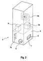
- FIG. 2 is an embodiment of an in FIG. 1 described charging case 4. This has several variants, which can either all be realized in a single charging case 4 or each individual variant also separately in a separate charging case. 4
- the charging case 4 has in its interior a charger 5.
- the charger 5 is connected via a power cord 6 with an external power source, such as a power outlet, connectable.
- a second connecting device 7 with second electrical contacts 8 is arranged on one of the outer surfaces of the charging case 4. This is connected to the charger 5.
- the second electrical contacts 8 are in the docked state, as to FIG. 1 described above, with the first electrical contacts 3 of the base case 1 in electrical contact.
- the charging case 4 has a further second connecting device 7a, which is arranged on a further outer surface of the charging case 4, which is opposite to the second connecting device 7. This makes it possible to connect another base case 1 directly to the charging case 4. Thus, an even larger number of power tools can be loaded simultaneously by the charging case 4.
- the power cord 6 is designed so that it against a force, usually a spring force, back into the charging case 4 is pulled in if it is not in a socket or other power source. This is comparable to a system known from vacuum cleaners. It is an automatic retractor. As a variant, another power cord 6 a is shown in dashed lines, which must be wound onto the charging case 4 by hand. This further power cable 6a is of course connected to the charger 5 and supplies it with power.
- the charging case 4 may have one or more charging bays for a replacement battery pack 9 or further replacement battery packs 9a. This can be done simultaneously with the charging of power tools, the pads of spare battery packs 9, 9a. Thus, it is possible to operate the power tool, after the battery pack is empty, with the replacement battery pack 9 or other spare battery packs 9a over a significantly longer period off-grid.
Landscapes
- Engineering & Computer Science (AREA)
- Mechanical Engineering (AREA)
- Charge And Discharge Circuits For Batteries Or The Like (AREA)
Claims (9)
- Mallette (1, 1a, 1b, 1c) pour une machine-outil électrique alimentée par batterie comportant un logement pour la machine-outil,
caractérisée par
un premier dispositif de liaison (2) sur au moins l'une de ses surfaces extérieures, et cette surface extérieure comporte des premiers contacts électriques (3) reliés au contact de chargeur dans le logement. - Mallette (1, 1a, 1b, 1c) selon la revendication précédente,
caractérisée en ce que
chacune des surfaces extérieures comporte d'autres éléments de liaison (2a) et d'autres contacts électriques (3a) reliés aux premiers contacts électriques (3). - Mallette (4) pour une machine-outil alimentée par batterie comportant un chargeur (5) à l'intérieur et un câble de réseau (6, 6a) extérieur, relié au chargeur,
ayant au moins un second dispositif de liaison (7) sur au moins l'une de ses surfaces extérieures,
caractérisée en ce que
des seconds contacts électriques (8) reliés au chargeur (5) sont réalisés sur cette surface extérieure. - Mallette (4) selon l'une des revendications précédentes,
caractérisée en ce que
chacune des surfaces extérieures comporte un autre second dispositif de liaison (7a) et d'autres troisièmes contacts reliés au chargeur (5). - Mallette (4) selon l'une des revendications précédentes 3 ou 4,
caractérisée en ce qu'
elle comporte au moins un logement de chargeur pour un groupe de batteries (9, 9a). - Mallette à chargeur (4) selon l'une des revendications précédentes 3 à 5,
caractérisée en ce que
le câble de réseau (6) s'extrait en agissant contre une force exercée par la mallette. - Mallette (1, 1a, 1b, 1c) ou mallette de chargeur (4) selon l'une des revendications précédentes,
caractérisée en ce qu'
elles comportent un premier et un second emplacement d'assemblage, par exemple un dispositif d'enclipsage ou un rail. - Ensemble formé d'au moins une mallette (1, 1a, 1b, 1c) et d'une mallette de chargeur (4) selon l'une des revendications précédentes,
caractérisé en ce que
la mallette (1, 1a, 1b, 1c) est reliée par le premier dispositif de liaison (2) au second dispositif de liaison (7) de la mallette à chargeur (4), les premiers contacts électriques (3) étant en permanence en contact avec les troisièmes contacts électriques (8), et un premier et un second dispositif d'assemblage coopèrent comme unités de liaison amovibles, garanties. - Ensemble selon l'une des revendications précédentes,
caractérisé en ce que
la mallette (1) reliée à la mallette de chargeur (4) peut recevoir une autre mallette (la, 1b, 1c) de façon que les premiers contacts (2a) respectifs se touchent en permanence et les premiers dispositifs d'assemblage coopèrent comme une unité de liaison amovible, garantie.
Applications Claiming Priority (2)
| Application Number | Priority Date | Filing Date | Title |
|---|---|---|---|
| DE10132830 | 2001-07-06 | ||
| DE2001132830 DE10132830A1 (de) | 2001-07-06 | 2001-07-06 | Transportkoffer und Ladekoffer für ein akkubetriebenes Elektrowerkzeug sowie Set aus diesen Koffern |
Publications (2)
| Publication Number | Publication Date |
|---|---|
| EP1273397A1 EP1273397A1 (fr) | 2003-01-08 |
| EP1273397B1 true EP1273397B1 (fr) | 2008-02-20 |
Family
ID=7690859
Family Applications (1)
| Application Number | Title | Priority Date | Filing Date |
|---|---|---|---|
| EP20020010531 Expired - Lifetime EP1273397B1 (fr) | 2001-07-06 | 2002-05-10 | Mallete à outil et mallete à chargeur de batterie pour un outil à main électrique et assortiment de malletes |
Country Status (2)
| Country | Link |
|---|---|
| EP (1) | EP1273397B1 (fr) |
| DE (2) | DE10132830A1 (fr) |
Cited By (1)
| Publication number | Priority date | Publication date | Assignee | Title |
|---|---|---|---|---|
| DE202017001477U1 (de) | 2017-03-16 | 2017-05-18 | ACD-Elektronik GmbH | Transportkoffer mit einer Ladevorrichtung für zumindest ein akkubetriebenes Elektrogerät |
Families Citing this family (5)
| Publication number | Priority date | Publication date | Assignee | Title |
|---|---|---|---|---|
| DE102004060294A1 (de) * | 2004-12-15 | 2006-06-22 | Robert Bosch Gmbh | Vorrichtung mit einem Handwerkzeugmaschinenkoffer |
| DE102009027573A1 (de) * | 2009-07-09 | 2011-01-13 | Robert Bosch Gmbh | Werkzeugkoffer, insbesondere Handwerkzeugkoffer |
| DE202010017022U1 (de) * | 2010-12-28 | 2011-03-24 | Robert Bosch Gmbh | Werkzeugkoffer |
| DE102014111316B3 (de) * | 2014-08-08 | 2016-01-07 | Josef Häringer | Transportable Kabeltrommel |
| DE102015109851A1 (de) * | 2015-04-08 | 2016-10-13 | Josef Häringer | Kabel-/Schlauchtrommel |
Family Cites Families (5)
| Publication number | Priority date | Publication date | Assignee | Title |
|---|---|---|---|---|
| DE9014132U1 (de) * | 1990-10-11 | 1991-01-10 | Busch, Wilhelm, 6419 Rasdorf | Ausbaufähige Station zur übersichtlichen Ablage von Akku-Handgeräten in Kombination mit deren Ladegeräten |
| US5459648A (en) * | 1994-09-02 | 1995-10-17 | Courtney; Glenn H. | Illuminated utility box |
| US5533843A (en) * | 1994-09-19 | 1996-07-09 | Chung; Lee H.-C. | Electric hand drill set |
| DE19614435A1 (de) * | 1996-04-12 | 1997-10-16 | Ee Signals Gmbh & Co Kg | Energieversorgungseinheit |
| FR2754526B1 (fr) * | 1996-10-16 | 1999-06-18 | Michelis Philippe | Dispositif de caisse a outil avec rallonge electrique |
-
2001
- 2001-07-06 DE DE2001132830 patent/DE10132830A1/de not_active Withdrawn
-
2002
- 2002-05-10 DE DE50211718T patent/DE50211718D1/de not_active Expired - Lifetime
- 2002-05-10 EP EP20020010531 patent/EP1273397B1/fr not_active Expired - Lifetime
Cited By (1)
| Publication number | Priority date | Publication date | Assignee | Title |
|---|---|---|---|---|
| DE202017001477U1 (de) | 2017-03-16 | 2017-05-18 | ACD-Elektronik GmbH | Transportkoffer mit einer Ladevorrichtung für zumindest ein akkubetriebenes Elektrogerät |
Also Published As
| Publication number | Publication date |
|---|---|
| DE50211718D1 (de) | 2008-04-03 |
| DE10132830A1 (de) | 2003-01-16 |
| EP1273397A1 (fr) | 2003-01-08 |
Similar Documents
| Publication | Publication Date | Title |
|---|---|---|
| EP0485784B1 (fr) | Chargeur pour batteries rechargeables | |
| DE4036374A1 (de) | Ladeeinrichtung fuer wiederaufladbare batterien | |
| DE102011005646A1 (de) | Mobiles Ladegerät | |
| DE102018102982A1 (de) | Ladegerät und Verfahren zum Laden eines Akkupacks | |
| DE19527757A1 (de) | Sicherheitseinrichtung für Verbinder | |
| WO2014166511A1 (fr) | Table élévatrice et installation de transport | |
| EP1273397B1 (fr) | Mallete à outil et mallete à chargeur de batterie pour un outil à main électrique et assortiment de malletes | |
| EP1414625B1 (fr) | Coffret dote d'un logement destine a un outil electrique a accumulateurs et systeme coffret comportant au moins deux coffrets de ce type | |
| WO2014005567A2 (fr) | Dispositif de charge pour un véhicule électrique et adaptateur | |
| DE102019100251A1 (de) | Transportable Ladestation | |
| EP2449933B1 (fr) | Aspirateur doté d'un dispositif de retenue de câble | |
| WO2022073993A1 (fr) | Accumulateur d'énergie mobile et procédé pour faire fonctionner un accumulateur d'énergie mobile | |
| DE102005037864A1 (de) | Ladesteckverbinder | |
| DE202005011891U1 (de) | Batteriegehäusestruktur für tragbare Geräte | |
| EP1675197A1 (fr) | Système de batterie, en particulier pour des trains | |
| DE102018219836A1 (de) | Dockingstation für ein Fahrzeug | |
| WO2016110351A1 (fr) | Module d'accumulateur et unité d'alimentation en courant à plusieurs modules d'accumulateur | |
| EP4066715B1 (fr) | Appareil de nettoyage fonctionnant sur batterie et?procédé de fonctionnement d'un appareil de nettoyage | |
| EP0370228B1 (fr) | Dispositif de connexion multiple | |
| DE29905884U1 (de) | Anordnung zur Halterung von Werkzeugen | |
| DE10008600A1 (de) | Mobiles Mehrgerätesystem | |
| DE68908898T2 (de) | Elektrisches stromverteilersystem. | |
| DE9015660U1 (de) | Ladeeinrichtung für wiederaufladbare Batterien | |
| DE102005008013B4 (de) | Ladegerät zur Erhaltungs-Ladung von Batterien | |
| EP2844603B1 (fr) | Bâti de transport |
Legal Events
| Date | Code | Title | Description |
|---|---|---|---|
| PUAI | Public reference made under article 153(3) epc to a published international application that has entered the european phase |
Free format text: ORIGINAL CODE: 0009012 |
|
| AK | Designated contracting states |
Kind code of ref document: A1 Designated state(s): AT BE CH CY DE DK ES FI FR GB GR IE IT LI LU MC NL PT SE TR |
|
| AX | Request for extension of the european patent |
Free format text: AL;LT;LV;MK;RO;SI |
|
| 17P | Request for examination filed |
Effective date: 20030708 |
|
| AKX | Designation fees paid |
Designated state(s): CH DE FR GB LI |
|
| GRAP | Despatch of communication of intention to grant a patent |
Free format text: ORIGINAL CODE: EPIDOSNIGR1 |
|
| GRAS | Grant fee paid |
Free format text: ORIGINAL CODE: EPIDOSNIGR3 |
|
| GRAA | (expected) grant |
Free format text: ORIGINAL CODE: 0009210 |
|
| AK | Designated contracting states |
Kind code of ref document: B1 Designated state(s): CH DE FR GB LI |
|
| REG | Reference to a national code |
Ref country code: GB Ref legal event code: FG4D Free format text: NOT ENGLISH |
|
| REG | Reference to a national code |
Ref country code: CH Ref legal event code: EP |
|
| REF | Corresponds to: |
Ref document number: 50211718 Country of ref document: DE Date of ref document: 20080403 Kind code of ref document: P |
|
| ET | Fr: translation filed | ||
| PLBE | No opposition filed within time limit |
Free format text: ORIGINAL CODE: 0009261 |
|
| STAA | Information on the status of an ep patent application or granted ep patent |
Free format text: STATUS: NO OPPOSITION FILED WITHIN TIME LIMIT |
|
| REG | Reference to a national code |
Ref country code: CH Ref legal event code: PL |
|
| 26N | No opposition filed |
Effective date: 20081121 |
|
| PG25 | Lapsed in a contracting state [announced via postgrant information from national office to epo] |
Ref country code: LI Free format text: LAPSE BECAUSE OF NON-PAYMENT OF DUE FEES Effective date: 20080531 Ref country code: CH Free format text: LAPSE BECAUSE OF NON-PAYMENT OF DUE FEES Effective date: 20080531 |
|
| PGFP | Annual fee paid to national office [announced via postgrant information from national office to epo] |
Ref country code: GB Payment date: 20130522 Year of fee payment: 12 |
|
| PGFP | Annual fee paid to national office [announced via postgrant information from national office to epo] |
Ref country code: FR Payment date: 20130604 Year of fee payment: 12 |
|
| GBPC | Gb: european patent ceased through non-payment of renewal fee |
Effective date: 20140510 |
|
| REG | Reference to a national code |
Ref country code: FR Ref legal event code: ST Effective date: 20150130 |
|
| PG25 | Lapsed in a contracting state [announced via postgrant information from national office to epo] |
Ref country code: GB Free format text: LAPSE BECAUSE OF NON-PAYMENT OF DUE FEES Effective date: 20140510 Ref country code: FR Free format text: LAPSE BECAUSE OF NON-PAYMENT OF DUE FEES Effective date: 20140602 |
|
| PGFP | Annual fee paid to national office [announced via postgrant information from national office to epo] |
Ref country code: DE Payment date: 20190716 Year of fee payment: 18 |
|
| REG | Reference to a national code |
Ref country code: DE Ref legal event code: R119 Ref document number: 50211718 Country of ref document: DE |
|
| PG25 | Lapsed in a contracting state [announced via postgrant information from national office to epo] |
Ref country code: DE Free format text: LAPSE BECAUSE OF NON-PAYMENT OF DUE FEES Effective date: 20201201 |