EP1273450A2 - Procédé de fabrication d'une éponge non homogéne et éponge ainsi fabriquée - Google Patents
Procédé de fabrication d'une éponge non homogéne et éponge ainsi fabriquée Download PDFInfo
- Publication number
- EP1273450A2 EP1273450A2 EP02013438A EP02013438A EP1273450A2 EP 1273450 A2 EP1273450 A2 EP 1273450A2 EP 02013438 A EP02013438 A EP 02013438A EP 02013438 A EP02013438 A EP 02013438A EP 1273450 A2 EP1273450 A2 EP 1273450A2
- Authority
- EP
- European Patent Office
- Prior art keywords
- sponge
- plates
- ink
- pressing device
- pore
- Prior art date
- Legal status (The legal status is an assumption and is not a legal conclusion. Google has not performed a legal analysis and makes no representation as to the accuracy of the status listed.)
- Granted
Links
- 238000004519 manufacturing process Methods 0.000 title description 3
- 239000011148 porous material Substances 0.000 claims abstract description 79
- 238000000034 method Methods 0.000 claims abstract description 48
- 238000009826 distribution Methods 0.000 claims abstract description 30
- 238000003825 pressing Methods 0.000 claims abstract description 15
- 238000007906 compression Methods 0.000 claims description 27
- 230000006835 compression Effects 0.000 claims description 18
- 230000007423 decrease Effects 0.000 claims description 4
- 238000005520 cutting process Methods 0.000 claims description 3
- 229920002635 polyurethane Polymers 0.000 claims description 3
- 239000004814 polyurethane Substances 0.000 claims description 3
- 229920000877 Melamine resin Polymers 0.000 claims description 2
- 239000004721 Polyphenylene oxide Substances 0.000 claims description 2
- JDSHMPZPIAZGSV-UHFFFAOYSA-N melamine Chemical compound NC1=NC(N)=NC(N)=N1 JDSHMPZPIAZGSV-UHFFFAOYSA-N 0.000 claims description 2
- 229920000728 polyester Polymers 0.000 claims description 2
- 229920000570 polyether Polymers 0.000 claims description 2
- 239000012815 thermoplastic material Substances 0.000 claims description 2
- 229920001169 thermoplastic Polymers 0.000 abstract description 4
- 239000004416 thermosoftening plastic Substances 0.000 abstract description 4
- 239000000463 material Substances 0.000 description 15
- 238000003860 storage Methods 0.000 description 5
- 230000002706 hydrostatic effect Effects 0.000 description 3
- 230000008901 benefit Effects 0.000 description 2
- 238000001816 cooling Methods 0.000 description 2
- 230000003247 decreasing effect Effects 0.000 description 2
- 238000005187 foaming Methods 0.000 description 2
- 238000002844 melting Methods 0.000 description 2
- 230000008018 melting Effects 0.000 description 2
- 239000000654 additive Substances 0.000 description 1
- 238000005273 aeration Methods 0.000 description 1
- 230000036760 body temperature Effects 0.000 description 1
- 230000000694 effects Effects 0.000 description 1
- 238000004049 embossing Methods 0.000 description 1
- 238000010438 heat treatment Methods 0.000 description 1
- 230000002427 irreversible effect Effects 0.000 description 1
- 230000000149 penetrating effect Effects 0.000 description 1
- 230000000717 retained effect Effects 0.000 description 1
- 238000007493 shaping process Methods 0.000 description 1
- 238000009736 wetting Methods 0.000 description 1
- 230000037303 wrinkles Effects 0.000 description 1
Images




Classifications
-
- B—PERFORMING OPERATIONS; TRANSPORTING
- B41—PRINTING; LINING MACHINES; TYPEWRITERS; STAMPS
- B41J—TYPEWRITERS; SELECTIVE PRINTING MECHANISMS, i.e. MECHANISMS PRINTING OTHERWISE THAN FROM A FORME; CORRECTION OF TYPOGRAPHICAL ERRORS
- B41J2/00—Typewriters or selective printing mechanisms characterised by the printing or marking process for which they are designed
- B41J2/005—Typewriters or selective printing mechanisms characterised by the printing or marking process for which they are designed characterised by bringing liquid or particles selectively into contact with a printing material
- B41J2/01—Ink jet
- B41J2/17—Ink jet characterised by ink handling
- B41J2/175—Ink supply systems ; Circuit parts therefor
- B41J2/17503—Ink cartridges
- B41J2/17559—Cartridge manufacturing
-
- B—PERFORMING OPERATIONS; TRANSPORTING
- B41—PRINTING; LINING MACHINES; TYPEWRITERS; STAMPS
- B41J—TYPEWRITERS; SELECTIVE PRINTING MECHANISMS, i.e. MECHANISMS PRINTING OTHERWISE THAN FROM A FORME; CORRECTION OF TYPOGRAPHICAL ERRORS
- B41J2/00—Typewriters or selective printing mechanisms characterised by the printing or marking process for which they are designed
- B41J2/005—Typewriters or selective printing mechanisms characterised by the printing or marking process for which they are designed characterised by bringing liquid or particles selectively into contact with a printing material
- B41J2/01—Ink jet
- B41J2/17—Ink jet characterised by ink handling
- B41J2/175—Ink supply systems ; Circuit parts therefor
- B41J2/17503—Ink cartridges
- B41J2/17513—Inner structure
Definitions
- the invention relates to a method for producing an inhomogeneous sponge, in particular for use as an ink storage, and one made by the process Sponge.
- Sponges used as ink storage in inkjet printers or so-called “inkjet systems” are used are known from the prior art. They consist of one large number of open pores (capillaries). These pores are when used with ink filled. The ink is stored in the sponge and is only by using the the wetting of the pore generated capillary force again. In this way it is created negative pressure in the ink system by using a sponge as an ink reservoir, which results from the capillary action of the individual sponge pores. Insist If only sponged from pores of a defined size, the vacuum would be during the ink removal from the sponge, apart from the hydrostatic pressure of the ink column, constant.
- the pore sizes or pore volumes are distributed statistically, i.e. their frequency can be approximated by a Gaussian distribution.
- a Gaussian distribution of the pore size is shown in FIG.
- the pore size distribution plays an important role.
- the contact angle between the sponge material and the ink is greater or less than 90 °
- the large ones first Pores are emptied because they generate the smallest capillary force, i.e. at the slightest negative pressure can be emptied.
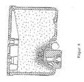
- the inhomogeneous pore distribution becomes towards the ink outlet in that the sponge locally through a nozzle protruding into the container space is compressed. This will create the desired capillary hierarchy (smaller pores at the ink outlet) stamped on the homogeneous sponge inside the cartridge.
- the sponge is made by external Forced kept in this partially compressed state.
- sponge material can have a constant, high pressure on cartridge walls and cartridge cover are exercised. It is also such a compression process not reliably reproducible.
- the materials involved differ when assembling the sponge Sponge shapes and thus capillary distributions.
- Another disadvantage of this method is that it compresses the Sponge can cause wrinkles. This has undesirable small sponge pores inside the sponge, which often cannot be emptied because of penetrating Air this volume of ink is cut off from the ink flow.
- a disadvantage of this cartridge design is finally the nozzle protruding into the container space. This takes up a part of the container volume and thus reduces the maximum storable Amount of ink and thus user benefit.
- the object of the invention is to use a method for producing a sponge specify as ink storage in ink cartridges, with the disadvantages described can be largely avoided.
- the object is achieved by a method according to claim 1.
- a method according to claim 1 is a body made of a porous thermoplastic material between at least two plates of a pressing device arranged and compressed under the action of heat and thermoplastic deformed, creating an inhomogeneous and irreversible density distribution is formed, or one or more density gradients.
- the process is carried out so that different areas of the porous body have different pore densities.
- the sponge material creates a sponge with the mean pore volume inside of the sponge body varies. 1, this means the distribution of the pore size can have a positive or negative excess, it can be asymmetrical, flat or steep or it can be two or more peaks.
- the advantage of this method is in particular in that the different pore volumes within the body also after the Keep cool.
- the sponge can therefore be cut or shaped in this way be that it can be inserted into a corresponding ink cartridge. Since the Sponge inside the ink cartridge no longer needs to be compressed are cartridge walls and the cartridge cover are not exposed to constant pressure. There is also no need for an inner nozzle to close areas of different pore volumes produce. The entire space inside the cartridge is therefore used for ink storage to disposal.
- the inhomogeneous distribution of the pore density or pore sizes or pore volumes becomes achieved according to the process by the different degrees of compression of individual areas of the porous sponge material under the influence of heat, i.e. through thermoplastic deformation of the sponge material.
- the different parts of the porous body be heated to different degrees. In areas of higher temperature the sponge structure softer than in areas with lower temperatures, and therefore under pressure deformed more thermoplastic, thus reducing the pore volume. By cooling of the sponge becomes this changed pore size distribution within the sponge body "Frozen". With different heating of different areas of the It must be ensured that the temperature of the sponge body is never at any point Melting point of the sponge material used, otherwise the entire pore structure can be destroyed.
- a temperature gradient inside the body during the method according to the invention can also be generated in that the shutter speed of the pressing device is relatively short is chosen. That is, the pressing process is ended before a homogeneous sponge body Temperature distribution has set.
- the choice of the respective shutter speed is also depending on how thick the sponge material is.
- the local compression factor i.e. the compression factor in a certain range of the sponge, plays a role in setting a density gradient within the Body.
- the compression factor is the ratio of unpressed to pressed Understand volume of the sponge.
- the sponge material is compressed more in some places than in others, i.e. the local compression factor varies within the body. For example can also be achieved in that the thickness of the sponge is not uniform is above its footprint.
- Another option is to put the sponge in the Arrange press device so that it is only partially covered by the press plates and thus a part of the sponge body is compressed and heated. Beyond that it is also possible to make the pressing surface of the plates inconsistent. That the bottom can have elevations and / or depressions. This option is described below be discussed in more detail. These are just a few examples of how a density gradient is to be trained within the body.
- the method according to the invention differs from previously used methods of Thermocompression as z. B. in JP 04357046, characterized in that the process is aimed at training a density gradient. While so far thermocompression has been used to achieve pores that are sized not be produced by the foaming process, the known method according to the invention modified so that permanent inhomogeneous sponge structures arise.
- the sponge materials known in the prior art can be used as sponge bodies for Ink sponges are used.
- the porous material of the sponge body can in particular contain one or more of the following: polyurethane polyether; Polyurethane-polyester; Melamine.
- the usual for these sponges can be used as required Additives are added.
- the porosity of these materials is determined by the usual Foaming process generated.
- the heat is preferably exerted on the body by at least one of the plates. This means that the plate (s) will be heated before the compression process starts. During the compression process, heat is transferred to the porous body over the side surfaces of the same, which are connected to the plate (s) stand. In this case, the heat penetrates from these side surfaces into the interior of the porous body. This creates a temperature gradient during the pressing process inside the porous body, which results in a density gradient.
- the plate temperature is between approximately 100 ° C and 250 ° C. As already mentioned, care must be taken that the temperature of the porous The body never reaches the melting temperature of the sponge material.
- the compression process takes about 10 to 90 minutes.
- the cooling of the Body preferably takes place after the end of the compression process.
- a value in the range between 1.5 and. is suitably used as the local compression factor 10 selected.
- the pore volumes of the original porous material can be based on this Partially reduced by a multiple.
- a generally known pressing device is used to carry out the method according to the invention used, between their stamps in the form of two plane-parallel plates
- the body is introduced from porous material and through which the body is avoided is subjected to pressure by transverse forces.
- both or all of the plates can also be heated, but to different degrees Temperatures. Also in this case there will be a temperature gradient inside the porous Train your body.
- the embodiment is particularly advantageous when the existing pore volume of the porous body as a whole, but with different Degree to be reduced.
- plates can be used in the method according to the invention be, which have a flat surface on their side facing the body.
- a density gradient can also be achieved in that the one used Sponge body three-dimensional on its sides facing the plates structured, in particular corrugated or serrated, surface.
- the body may have a non-uniform thickness over its base area. The thicker ones Areas of the body are then compressed more, i.e. the local compression factor is bigger in these places. Accordingly, the pore volume decreases at these points.
- plates are selected which are based on the Body-facing side a three-dimensionally structured, especially wavy or serrated Have surface.
- the press plates act like an embossing stamp under the influence of which the local compression factor is varied, since the sponge material in those places where the plates bulge away from the sponge body there is a weaker compression.
- a similar effect can, for example can also be achieved in that several printing plates are used, each of which exert different pressures.
- a sponge body is used in the method according to the invention cuboid body used.
- This variant is particularly related to structured press plates advantageous.
- the compressed sponge body After the compressed sponge body has cooled, it can, preferably by Cut up, divided into several units. This can also be used for a special Cartridge necessary shape of the sponge can be made.
- the sponge produced by the method according to the invention is characterized in that that its average pore volume or its pore distribution within the sponge varied.
- the sponge formed has one Area of minimal mean pore volume in an edge area of the sponge. That the average pore volume, starting from this edge area, increases towards the inside of the Sponge body towards. This edge area becomes contiguous when the sponge is used arranged on an ink outlet of the cartridge, so that the anisotropy of the Capillary forces run in the desired direction.
- the sponge according to the invention can be designed so that its average pore volume decreases continuously from one side to the other.
- the characteristic sponge curve is significantly smoothed in an advantageous manner compared to FIG.
- Figure 1 shows the relative distribution of the pore size or the pore volume, as in a conventional ink sponge.
- the associated pressure curve Figure 2 shows the removal of ink from such a sponge.
- FIG 3 are the flow conditions of the ink within the ink storage sponge an ink cartridge shown.
- the ink When the ink is removed through the designated ink removal opening, or the outlet, the removed ink must pass through continuously flowing ink can be replaced from other sponge areas.
- This ink shift within the sponge, or this afterflow of ink is characterized by a Sponge with an inhomogeneous pore distribution supports when the pores to the ink outlet are getting finer and finer.
- FIG. One way to achieve this capillary gradient due to decreasing pore diameter towards the outlet is shown in FIG.
- FIGS. 5a to 5c The principle of thermal sponge compression is shown in FIGS. 5a to 5c: A body 1 made of a porous material is here between two plates 2, 3 Press device arranged and under the action of pressure and heat to a fraction compressed to its original volume. After compression, it is replaced by the Plates exerted pressure, the porous body taking its compressed form maintains. The homogeneous reduction of the pore volume compared to the process The initial state, and thus the increase in capillary action, takes place here in particular towards normal to the plates.
- thermocompression process is carried out inhomogeneously, like this is shown in Figures 6a to 6c.
- the plates 2, 3 are heated to the supply heat to the porous body 1 during the compression process.
- the Shutter speed kept so short that there is no uniform temperature over the whole porous body 1 can adjust.
- different, different strengths compressed areas within the porous body 1 arise. So are the edge areas 1a more compressed and therefore have a lower average pore volume than that central area 1b. As the sponge cools, this changes the pore size distribution frozen.
- FIGS. 7a to 7c show a further possibility of generating an inhomogeneous pore distribution shown in the sponge body 1.
- the top plate 2 is on a heated to a higher temperature than the lower plate 3.
- the sponge structure becomes softer due to the increased heat in the upper area, than is the case in the lower area of the sponge and is therefore more compressed. It this results in a one-dimensional anisotropy of the pore distribution in the sponge.
- Figures 8a and 8b represent a third way of carrying out the invention Process there.
- no plane-parallel, i.e. H. cuboid, sponge plate used as is the case in the previous examples, but a sponge plate with three-dimensional surface structure.
- This sponge plate structured in this way compressed you get again a plane-parallel plate, but with an inhomogeneous pore distribution.
- the inhomogeneous pore distribution results from the fact that the areas 1a larger thickness can be compressed more.
- By cutting out the individual Sponges from the entire plate create an inhomogeneous sponge for each cartridge defined pore distribution. Examples of cut edges for subdivision into single sponge areas are represented by lines 4.
- the different pore distribution can Example serve the hydrostatic pressure component when ink is removed to compensate for slanted sponge cartridges.
- this example works therefore, by shaping the original sponge during the forming process to be plane-parallel Sponge plate to create a defined inhomogeneous pore distribution.
- FIGS. 9a to 9c A last example of a method according to the invention is shown in FIGS. 9a to 9c.
- the plates 2, 3 of the pressing device in this case designed as a stamp. This creates Sponge zones 1a, which are characterized by stronger compression than sponge zones 1b are. It can also be used to adapt the sponge to a specified one Ink tank geometry done.
Landscapes
- Engineering & Computer Science (AREA)
- Manufacturing & Machinery (AREA)
- Ink Jet (AREA)
- Manufacture Of Porous Articles, And Recovery And Treatment Of Waste Products (AREA)
Priority Applications (1)
| Application Number | Priority Date | Filing Date | Title |
|---|---|---|---|
| EP10185572A EP2316651A1 (fr) | 2001-07-05 | 2002-06-13 | Procédé de fabrication d'une éponge non homogène |
Applications Claiming Priority (2)
| Application Number | Priority Date | Filing Date | Title |
|---|---|---|---|
| DE10132511A DE10132511A1 (de) | 2001-07-05 | 2001-07-05 | Verfahren zur Herstellung eines inhomogenen Schwammes und danach hergestellter Schwamm |
| DE10132511 | 2001-07-05 |
Related Child Applications (1)
| Application Number | Title | Priority Date | Filing Date |
|---|---|---|---|
| EP10185572.4 Division-Into | 2010-10-01 |
Publications (3)
| Publication Number | Publication Date |
|---|---|
| EP1273450A2 true EP1273450A2 (fr) | 2003-01-08 |
| EP1273450A3 EP1273450A3 (fr) | 2003-11-19 |
| EP1273450B1 EP1273450B1 (fr) | 2011-01-12 |
Family
ID=7690649
Family Applications (2)
| Application Number | Title | Priority Date | Filing Date |
|---|---|---|---|
| EP02013438A Expired - Lifetime EP1273450B1 (fr) | 2001-07-05 | 2002-06-13 | Procédé de fabrication d'une éponge non homogène |
| EP10185572A Withdrawn EP2316651A1 (fr) | 2001-07-05 | 2002-06-13 | Procédé de fabrication d'une éponge non homogène |
Family Applications After (1)
| Application Number | Title | Priority Date | Filing Date |
|---|---|---|---|
| EP10185572A Withdrawn EP2316651A1 (fr) | 2001-07-05 | 2002-06-13 | Procédé de fabrication d'une éponge non homogène |
Country Status (3)
| Country | Link |
|---|---|
| EP (2) | EP1273450B1 (fr) |
| AT (1) | ATE495018T1 (fr) |
| DE (2) | DE10132511A1 (fr) |
Cited By (1)
| Publication number | Priority date | Publication date | Assignee | Title |
|---|---|---|---|---|
| US20210169299A1 (en) * | 2018-08-13 | 2021-06-10 | Bright Box Lab, LLC | Layered scrub |
Families Citing this family (2)
| Publication number | Priority date | Publication date | Assignee | Title |
|---|---|---|---|---|
| DE10306198A1 (de) * | 2003-02-13 | 2004-08-26 | Coronet-Werke Gmbh | Reinigungs- oder Applikationsschwamm und Verfahren zu seiner Herstellung |
| CN111251524B (zh) * | 2020-01-21 | 2021-06-08 | 四川大学 | 基于梯度温度的梯度多孔聚合物泡沫材料的制备方法 |
Citations (2)
| Publication number | Priority date | Publication date | Assignee | Title |
|---|---|---|---|---|
| EP0709210A1 (fr) | 1994-10-31 | 1996-05-01 | Hewlett-Packard Company | Dispositif d'écriture à jet d'encre à gradient capillaire |
| US6042225A (en) | 1994-10-31 | 2000-03-28 | Hewlett-Packard Company | Ink-jet pen with one-piece pen body |
Family Cites Families (7)
| Publication number | Priority date | Publication date | Assignee | Title |
|---|---|---|---|---|
| JP3160312B2 (ja) | 1990-07-10 | 2001-04-25 | キヤノン株式会社 | インクジェットカートリッジ及び該カートリッジを用いた記録装置 |
| GB2249054B (en) * | 1990-07-10 | 1994-10-19 | Canon Kk | Ink tank,ink jet cartridge having the tank,and ink jet recording apparatus having the cartridge |
| AT401268B (de) * | 1992-10-15 | 1996-07-25 | Greiner & Soehne C A | Schaumstoffelement, insbesondere formteil aus einer oder mehreren platten aus schaumstoff und verfahren zu seiner herstellung |
| CA2168141C (fr) * | 1995-02-06 | 2000-11-21 | Thyagaraj Sarada | Methode de fabrication d'une mousse de porosite diverse servant au dosage de l'encre et d'autres liquides |
| US5892527A (en) * | 1996-04-22 | 1999-04-06 | Lexmark International, Inc. | Ink cartridge with an unfelted foam and method of printing using the same |
| GB2316037B (en) | 1996-08-02 | 2000-03-22 | Seiko Epson Corp | Ink cartridge and a printing device using the ink cartridge |
| AU5226099A (en) * | 1998-07-24 | 2000-02-14 | 3Wg, Incorporated | Multiple members acting singularly for retaining fluid |
-
2001
- 2001-07-05 DE DE10132511A patent/DE10132511A1/de not_active Ceased
-
2002
- 2002-06-13 AT AT02013438T patent/ATE495018T1/de active
- 2002-06-13 EP EP02013438A patent/EP1273450B1/fr not_active Expired - Lifetime
- 2002-06-13 DE DE50214854T patent/DE50214854D1/de not_active Expired - Lifetime
- 2002-06-13 EP EP10185572A patent/EP2316651A1/fr not_active Withdrawn
Patent Citations (2)
| Publication number | Priority date | Publication date | Assignee | Title |
|---|---|---|---|---|
| EP0709210A1 (fr) | 1994-10-31 | 1996-05-01 | Hewlett-Packard Company | Dispositif d'écriture à jet d'encre à gradient capillaire |
| US6042225A (en) | 1994-10-31 | 2000-03-28 | Hewlett-Packard Company | Ink-jet pen with one-piece pen body |
Cited By (2)
| Publication number | Priority date | Publication date | Assignee | Title |
|---|---|---|---|---|
| US20210169299A1 (en) * | 2018-08-13 | 2021-06-10 | Bright Box Lab, LLC | Layered scrub |
| US11786099B2 (en) * | 2018-08-13 | 2023-10-17 | Bright Box Labs, LLC | Layered scrub |
Also Published As
| Publication number | Publication date |
|---|---|
| EP2316651A1 (fr) | 2011-05-04 |
| ATE495018T1 (de) | 2011-01-15 |
| DE10132511A1 (de) | 2003-01-30 |
| EP1273450A3 (fr) | 2003-11-19 |
| DE50214854D1 (de) | 2011-02-24 |
| EP1273450B1 (fr) | 2011-01-12 |
Similar Documents
| Publication | Publication Date | Title |
|---|---|---|
| DE69320345T2 (de) | Schale zum aufnehmen von nahrungsmitteln und verfahren zu ihrer herstellung | |
| DE2806401C2 (de) | Nur in einer Richtung flüssigkeitsdurchlässige Folie | |
| DE69401634T2 (de) | Verfahren zur herstellung einer karte, die mindestens einen elektronischen baustein enthält,und nach einem solchen verfahren hergestellte karte | |
| DE60023806T2 (de) | Farbspender | |
| DE102006055078A1 (de) | Vorrichtung zum schichtweisen Herstellen eines dreidimensionalen Objekts | |
| DE3326580A1 (de) | Verfahren und anordnung zur herstellung einer duesenplatte fuer tintenstrahldrucker | |
| DE69104183T2 (de) | Wirbelbettvorrichtung und Verfahren zu ihrer Herstellung. | |
| DE60112296T2 (de) | Verfahren zur Herstellung einer Platte umfassend eine Zwischenformung und eine Endformung | |
| AT823U1 (de) | Filter für aufgussgetränke, insbesondere kaffeefilter und verfahren zur herstellung eines derartigen filters | |
| DE3435704C1 (de) | Verfahren und Vorrichtung zur Herstellung eines Einbandes oder dergleichen sowie Einband | |
| DE69604805T2 (de) | Verfahren zur herstellung einer verpackung | |
| EP1273450B1 (fr) | Procédé de fabrication d'une éponge non homogène | |
| DE10142624A1 (de) | Verfahren und Vorrichtung zum Pressen von Metallpulver zu einem Preßling | |
| DE3100361C2 (de) | Verfahren zur Herstellung einer Farbwalze | |
| DE102015215571A1 (de) | Kühlkörper für eine elektronische Komponente und Verfahren zu dessen Herstellung | |
| DE10151013B4 (de) | Vorrichtung zur Formgebung einer Platte aus tiefziehfähigem Material, insbesondere Blech | |
| DE60020615T2 (de) | Laminat und dessen Verwendung als Behälter | |
| DE2949731A1 (de) | Vorrichtung und verfahren zum formen von geripptem flaechenmaterial | |
| EP0234020B1 (fr) | Procédé de fabrication d'un corps comprimé poreux | |
| DE69716541T3 (de) | Formkörper aus gepresstem Pulver und Verfahren seiner Herstellung | |
| DE69705913T2 (de) | Stempelvorrichtung | |
| DE69806081T2 (de) | Schablonendruckvorrichtung | |
| DE102004035311A1 (de) | Verfahren zum Herstellen mindestens eines Bereichs einer Filterstruktur, insbesondere für einen Partikelfilter im Abgassystem einer Brennkraftmaschine | |
| DE3735729A1 (de) | Verfahren zum herstellen eines aktivkohlefilters und nach dem verfahren hergestelltes aktivkohlefilter | |
| DE10202365A1 (de) | Tintenbehälter mit Schwamm und Verfahren zu dessen Herstellung |
Legal Events
| Date | Code | Title | Description |
|---|---|---|---|
| PUAI | Public reference made under article 153(3) epc to a published international application that has entered the european phase |
Free format text: ORIGINAL CODE: 0009012 |
|
| AK | Designated contracting states |
Kind code of ref document: A2 Designated state(s): AT BE CH CY DE DK ES FI FR GB GR IE IT LI LU MC NL PT SE TR |
|
| AX | Request for extension of the european patent |
Free format text: AL;LT;LV;MK;RO;SI |
|
| PUAL | Search report despatched |
Free format text: ORIGINAL CODE: 0009013 |
|
| AK | Designated contracting states |
Kind code of ref document: A3 Designated state(s): AT BE CH CY DE DK ES FI FR GB GR IE IT LI LU MC NL PT SE TR |
|
| AX | Request for extension of the european patent |
Extension state: AL LT LV MK RO SI |
|
| 17P | Request for examination filed |
Effective date: 20040506 |
|
| AKX | Designation fees paid |
Designated state(s): AT BE CH CY DE DK ES FI FR GB GR IE IT LI LU MC NL PT SE TR |
|
| 17Q | First examination report despatched |
Effective date: 20040723 |
|
| 17Q | First examination report despatched |
Effective date: 20040723 |
|
| GRAP | Despatch of communication of intention to grant a patent |
Free format text: ORIGINAL CODE: EPIDOSNIGR1 |
|
| RTI1 | Title (correction) |
Free format text: MANUFACTURING PROCESS FOR INHOMOGENEOUS SPONGE |
|
| GRAS | Grant fee paid |
Free format text: ORIGINAL CODE: EPIDOSNIGR3 |
|
| RAP1 | Party data changed (applicant data changed or rights of an application transferred) |
Owner name: PELIKAN HARDCOPY PRODUCTION AG |
|
| GRAA | (expected) grant |
Free format text: ORIGINAL CODE: 0009210 |
|
| AK | Designated contracting states |
Kind code of ref document: B1 Designated state(s): AT BE CH CY DE DK ES FI FR GB GR IE IT LI LU MC NL PT SE TR |
|
| REG | Reference to a national code |
Ref country code: GB Ref legal event code: FG4D Free format text: NOT ENGLISH |
|
| REG | Reference to a national code |
Ref country code: CH Ref legal event code: EP |
|
| REG | Reference to a national code |
Ref country code: IE Ref legal event code: FG4D Free format text: LANGUAGE OF EP DOCUMENT: GERMAN |
|
| REF | Corresponds to: |
Ref document number: 50214854 Country of ref document: DE Date of ref document: 20110224 Kind code of ref document: P |
|
| REG | Reference to a national code |
Ref country code: DE Ref legal event code: R096 Ref document number: 50214854 Country of ref document: DE Effective date: 20110224 |
|
| REG | Reference to a national code |
Ref country code: NL Ref legal event code: VDEP Effective date: 20110112 |
|
| PG25 | Lapsed in a contracting state [announced via postgrant information from national office to epo] |
Ref country code: ES Free format text: LAPSE BECAUSE OF FAILURE TO SUBMIT A TRANSLATION OF THE DESCRIPTION OR TO PAY THE FEE WITHIN THE PRESCRIBED TIME-LIMIT Effective date: 20110423 Ref country code: GR Free format text: LAPSE BECAUSE OF FAILURE TO SUBMIT A TRANSLATION OF THE DESCRIPTION OR TO PAY THE FEE WITHIN THE PRESCRIBED TIME-LIMIT Effective date: 20110413 Ref country code: PT Free format text: LAPSE BECAUSE OF FAILURE TO SUBMIT A TRANSLATION OF THE DESCRIPTION OR TO PAY THE FEE WITHIN THE PRESCRIBED TIME-LIMIT Effective date: 20110512 Ref country code: SE Free format text: LAPSE BECAUSE OF FAILURE TO SUBMIT A TRANSLATION OF THE DESCRIPTION OR TO PAY THE FEE WITHIN THE PRESCRIBED TIME-LIMIT Effective date: 20110112 |
|
| REG | Reference to a national code |
Ref country code: IE Ref legal event code: FD4D |
|
| PG25 | Lapsed in a contracting state [announced via postgrant information from national office to epo] |
Ref country code: CY Free format text: LAPSE BECAUSE OF FAILURE TO SUBMIT A TRANSLATION OF THE DESCRIPTION OR TO PAY THE FEE WITHIN THE PRESCRIBED TIME-LIMIT Effective date: 20110112 Ref country code: FI Free format text: LAPSE BECAUSE OF FAILURE TO SUBMIT A TRANSLATION OF THE DESCRIPTION OR TO PAY THE FEE WITHIN THE PRESCRIBED TIME-LIMIT Effective date: 20110112 Ref country code: NL Free format text: LAPSE BECAUSE OF FAILURE TO SUBMIT A TRANSLATION OF THE DESCRIPTION OR TO PAY THE FEE WITHIN THE PRESCRIBED TIME-LIMIT Effective date: 20110112 |
|
| PG25 | Lapsed in a contracting state [announced via postgrant information from national office to epo] |
Ref country code: DK Free format text: LAPSE BECAUSE OF FAILURE TO SUBMIT A TRANSLATION OF THE DESCRIPTION OR TO PAY THE FEE WITHIN THE PRESCRIBED TIME-LIMIT Effective date: 20110112 Ref country code: IE Free format text: LAPSE BECAUSE OF FAILURE TO SUBMIT A TRANSLATION OF THE DESCRIPTION OR TO PAY THE FEE WITHIN THE PRESCRIBED TIME-LIMIT Effective date: 20110112 |
|
| PLBE | No opposition filed within time limit |
Free format text: ORIGINAL CODE: 0009261 |
|
| STAA | Information on the status of an ep patent application or granted ep patent |
Free format text: STATUS: NO OPPOSITION FILED WITHIN TIME LIMIT |
|
| 26N | No opposition filed |
Effective date: 20111013 |
|
| PG25 | Lapsed in a contracting state [announced via postgrant information from national office to epo] |
Ref country code: IT Free format text: LAPSE BECAUSE OF FAILURE TO SUBMIT A TRANSLATION OF THE DESCRIPTION OR TO PAY THE FEE WITHIN THE PRESCRIBED TIME-LIMIT Effective date: 20110112 |
|
| BERE | Be: lapsed |
Owner name: PELIKAN HARDCOPY PRODUCTION A.G. Effective date: 20110630 |
|
| REG | Reference to a national code |
Ref country code: DE Ref legal event code: R082 Ref document number: 50214854 Country of ref document: DE Representative=s name: MEISSNER, BOLTE & PARTNER GBR, DE |
|
| REG | Reference to a national code |
Ref country code: CH Ref legal event code: PL |
|
| REG | Reference to a national code |
Ref country code: DE Ref legal event code: R097 Ref document number: 50214854 Country of ref document: DE Effective date: 20111013 |
|
| GBPC | Gb: european patent ceased through non-payment of renewal fee |
Effective date: 20110613 |
|
| REG | Reference to a national code |
Ref country code: DE Ref legal event code: R081 Ref document number: 50214854 Country of ref document: DE Owner name: PELIKAN HARDCOPY PRODUCTION AG, CH Free format text: FORMER OWNER: PELIKAN HARDCOPY PRODUCTION AG, EGG, CH Effective date: 20120116 Ref country code: DE Ref legal event code: R082 Ref document number: 50214854 Country of ref document: DE Representative=s name: MEISSNER, BOLTE & PARTNER GBR, DE Effective date: 20120116 Ref country code: DE Ref legal event code: R082 Ref document number: 50214854 Country of ref document: DE Representative=s name: MEISSNER BOLTE PATENTANWAELTE RECHTSANWAELTE P, DE Effective date: 20120116 |
|
| REG | Reference to a national code |
Ref country code: FR Ref legal event code: ST Effective date: 20120229 |
|
| PG25 | Lapsed in a contracting state [announced via postgrant information from national office to epo] |
Ref country code: BE Free format text: LAPSE BECAUSE OF NON-PAYMENT OF DUE FEES Effective date: 20110630 |
|
| PG25 | Lapsed in a contracting state [announced via postgrant information from national office to epo] |
Ref country code: LI Free format text: LAPSE BECAUSE OF NON-PAYMENT OF DUE FEES Effective date: 20110630 Ref country code: CH Free format text: LAPSE BECAUSE OF NON-PAYMENT OF DUE FEES Effective date: 20110630 Ref country code: FR Free format text: LAPSE BECAUSE OF NON-PAYMENT OF DUE FEES Effective date: 20110630 |
|
| PG25 | Lapsed in a contracting state [announced via postgrant information from national office to epo] |
Ref country code: GB Free format text: LAPSE BECAUSE OF NON-PAYMENT OF DUE FEES Effective date: 20110613 |
|
| REG | Reference to a national code |
Ref country code: DE Ref legal event code: R084 Ref document number: 50214854 Country of ref document: DE Effective date: 20120703 |
|
| REG | Reference to a national code |
Ref country code: AT Ref legal event code: MM01 Ref document number: 495018 Country of ref document: AT Kind code of ref document: T Effective date: 20110613 |
|
| PGFP | Annual fee paid to national office [announced via postgrant information from national office to epo] |
Ref country code: DE Payment date: 20120827 Year of fee payment: 11 |
|
| PG25 | Lapsed in a contracting state [announced via postgrant information from national office to epo] |
Ref country code: AT Free format text: LAPSE BECAUSE OF NON-PAYMENT OF DUE FEES Effective date: 20110613 |
|
| PG25 | Lapsed in a contracting state [announced via postgrant information from national office to epo] |
Ref country code: MC Free format text: LAPSE BECAUSE OF NON-PAYMENT OF DUE FEES Effective date: 20110630 |
|
| PG25 | Lapsed in a contracting state [announced via postgrant information from national office to epo] |
Ref country code: LU Free format text: LAPSE BECAUSE OF NON-PAYMENT OF DUE FEES Effective date: 20110613 |
|
| PG25 | Lapsed in a contracting state [announced via postgrant information from national office to epo] |
Ref country code: TR Free format text: LAPSE BECAUSE OF FAILURE TO SUBMIT A TRANSLATION OF THE DESCRIPTION OR TO PAY THE FEE WITHIN THE PRESCRIBED TIME-LIMIT Effective date: 20110112 |
|
| REG | Reference to a national code |
Ref country code: DE Ref legal event code: R119 Ref document number: 50214854 Country of ref document: DE Effective date: 20140101 |
|
| PG25 | Lapsed in a contracting state [announced via postgrant information from national office to epo] |
Ref country code: DE Free format text: LAPSE BECAUSE OF NON-PAYMENT OF DUE FEES Effective date: 20140101 |