EP1273697A2 - Dispositif de dégazage de suspension, notamment de suspension fibreuse - Google Patents
Dispositif de dégazage de suspension, notamment de suspension fibreuse Download PDFInfo
- Publication number
- EP1273697A2 EP1273697A2 EP02013117A EP02013117A EP1273697A2 EP 1273697 A2 EP1273697 A2 EP 1273697A2 EP 02013117 A EP02013117 A EP 02013117A EP 02013117 A EP02013117 A EP 02013117A EP 1273697 A2 EP1273697 A2 EP 1273697A2
- Authority
- EP
- European Patent Office
- Prior art keywords
- container
- overflow
- suspension
- gas
- wall
- Prior art date
- Legal status (The legal status is an assumption and is not a legal conclusion. Google has not performed a legal analysis and makes no representation as to the accuracy of the status listed.)
- Granted
Links
Images


Classifications
-
- B—PERFORMING OPERATIONS; TRANSPORTING
- B01—PHYSICAL OR CHEMICAL PROCESSES OR APPARATUS IN GENERAL
- B01D—SEPARATION
- B01D19/00—Degasification of liquids
- B01D19/0042—Degasification of liquids modifying the liquid flow
- B01D19/0047—Atomizing, spraying, trickling
-
- D—TEXTILES; PAPER
- D21—PAPER-MAKING; PRODUCTION OF CELLULOSE
- D21D—TREATMENT OF THE MATERIALS BEFORE PASSING TO THE PAPER-MAKING MACHINE
- D21D5/00—Purification of the pulp suspension by mechanical means; Apparatus therefor
- D21D5/26—De-aeration of paper stock
Definitions
- the invention relates to a device for degassing suspension, in particular of fiber suspension, consisting of a preferably elongated and lying cylindrical containers with a horizontal or approximate horizontal container axis and a container outer wall, with at least one preferably parallel or approximately parallel to the container axis Distribution pipe that is outside or inside the container and from the at least one jet pipe, preferably a plurality of successive ones Jet pipes, for feeding suspension into the container, and / or with at least one suspension communicating with the container and suspension feeding chamber, the communicating chamber essentially above the liquid level of the supplied suspension in the container lies, with at least one preferably attached in the central region of the container Outlet opening for at least one gas-free suspension, with at least one outlet opening in the container for at least one separated gas and for at least one by means of at least one overflow separated, excess suspension and with means for producing a Negative pressure in the container.
- the invention further relates to a method for degassing suspension, in particular of fiber suspension, one being under negative pressure
- Container suspension is fed and gas-free suspension preferably in middle area of the container, separated gas preferably in the upper Inside of the container and deposited, excess suspension over at least one overflow is discharged.
- the term “suspension” can also include white water with the essential constituents fine substance and ash or clarified water with a minimal proportion of fine substance and ash.
- the container can also take any spatial shape, for example the shape of a cuboid, a sphere or at least one bowl.
- the three-dimensional shape of the container in the present invention is therefore not limited to an elongated and lying cylindrical three-dimensional shape.
- the suspension to be fed to the paper or cardboard machine is removed through an opening in the bottom of the container, which is of course connected with the idea of deriving the most gas-free suspension from the container.
- a vacuum is generated in the container by means of a vacuum pump, preferably a vacuum pump, the gas escaping from the container through the vacuum pump with line.
- the degassing ability is improved by adding the suspension, which still contains gas, through jet pipes above the liquid level in the container, the gas which may be present in the suspension as bubbles being separated before the suspension added with the suspension already present in Connection is coming.
- a preferably single overflow serves to stabilize the liquid level in the container, with about a partial flow of approximately 1% to 10% of the total amount of suspension introduced into the container and also light impurities accumulating on the liquid surface of the container usually flowing over its edge.
- the separated, excess suspension together with light impurities then flows to further treatment (cleaner or sorter), where efforts are made to separate the light impurities from the suspension and to return the suspension to the circuit.
- German laid-open specification DE 42 34 522 A1 discloses a device for degassing suspension (degassing container) used in the paper and pulp industry in accordance with the aforementioned preamble of the present invention.
- the dividing wall forming the overflow for the separated, excess suspension is arranged essentially at the same level as the rear edge of the outlet connection for gas-free suspension perpendicular to the container axis, and the overflow for the separated, excess suspension itself is preferably towards the outlet connection against the flow direction in the container inclined or curved.
- Further disclosures regarding the position and shape of the partition forming the overflow for the deposited excess suspension can be found in German Offenlegungsschrift DE 32 19 749 A1, in PCT application WO 97/15717 A1 and in US Pat. No.
- the applicant's unpublished German patent application DE 200 08 711.8 also discloses a device for degassing suspension. It is provided that the at least one outlet opening for the separated, excess suspension — viewed in the flow direction thereof — is preceded by an overflow designed as an overflow pipe with an overflow height and an overflow length.
- this device allows a greater degree of freedom with regard to the position and shape of the overflow, it does not allow an optimal arrangement of the overflow in terms of flow technology between the supply of suspension and the discharge of gas-free suspension.
- this object is achieved in a device according to the preamble of claim 1 in that the overflow is designed as at least one overflow mounted in the outer wall of the container and running parallel to the axis of the container with an overflow edge and that the overflow is at least one overflow system for removing the separated, excess Suspension is subordinate.
- This configuration of the overflow creates the possibility of arranging it definitely in a fluidically optimal position between the supply of suspension and the discharge of gas-free suspension with further improvement of the hydraulics, with the additional advantage of low device costs being achieved.
- the overflow is in or approximately in Area of the outlet opening, preferably in the center of the outlet opening, for the gas-free Suspension formed in the outer wall of the container. This will make the hydraulics the device further improved, since the suspension supplied in the lower Gas-free area and the gas-free excess in the upper area becomes.
- the overflow is in shape of at least two individual overflows on both sides in the outer wall of the tank at least one individual overflow edge is formed.
- the overflow has an overflow edge with a total overflow edge length in the range from 1 m to 10 m, preferably from 2 m to 7 m, and / or an open total overflow surface in the Range from 0.3 m 2 to 6 m 2 , preferably from 0.4 m 2 to 5 m 2 .
- the overflow surface of the individual overflow has an aerodynamically optimal outer contour, preferably the shape of a rectangle, a circle, an oval or a regular or an irregular polygon.
- a plurality of overflow surfaces, in particular circles, of individual overflows are introduced into the outer wall of the container, these are preferably formed at regular intervals (divisions) from one another along a center line in the outer wall of the container, since this improves the hydraulics in a positive manner.
- the individual overflows open individually or in groups or sections directly by means of at least one overflow pipe or by means of at least one overflow chamber designed as a half-shell in the outer wall of the tank and at least one downstream overflow pipe into the overflow system, which is preferably arranged below the tank, since this type of supply line is inexpensive and can be implemented reliably.
- the Outlet opening for the gas-free suspension - in the flow direction of the gas-free Suspension seen - a hydraulic stabilizer is arranged downstream.
- This Stabilizer which, for example, as a retention tank with certain fluidic properties is formed, has a buffer capacity for the gas-free suspension and thereby prevents it from occurring of pulsations that are required for the subsequent manufacturing process in a paper or Cardboard machines are extremely disadvantageous.
- the means for generating the Vacuum in the container one vacuum connection, one vacuum line each and are at least one vacuum pump with line and preferably in upper interior of the container are attached. It goes without saying that several vacuum connections each individually with a separate vacuum line and a separate vacuum pump with line as well individual vacuum lines and a common vacuum pump with Line can be operated.
- the distribution pipe is connected to the Container axis is parallel or approximately parallel.
- the distribution pipe can furthermore lie outside or inside the container.
- this object is achieved in a method according to the preamble of claim 16 in that the separated, excess suspension is discharged laterally via an overflow edge which is arranged in the outer wall of the container and preferably runs parallel to the axis of the container.
- This method according to the invention creates the possibility of arranging the overflow definitely in a fluidically optimal position between the supply of suspension and the discharge of gas-free suspension with further improvement of the hydraulics, with the additional advantage of low device costs being achieved.
- a device 1 for degassing a suspension 2 consisting of an elongated and lying cylindrical container 3 with a container axis 3a and a container outer wall 3b, to which the suspension 2 to be fed to the paper or board machine is shown as a thin one Mixture is supplied via at least one distribution pipe 4, preferably parallel to the container axis 3a, from which a plurality of successive jet pipes 5 for feeding suspension 2 into the container 3 are fed.
- the supplied, still gas-containing suspension 2 is introduced through jet pipes 5 above the liquid level 6 in the container 3, the gas 7 possibly present in the added suspension 2 already being separated before the added one Suspension 2 comes into contact with suspension 2 already present in container 3.
- the jet pipes 5 end shortly before the container ceiling 8, so that the degassing process of the suspension 2 is again positively supported, since the suspension 2 collides with the container ceiling 8.
- the suspension 2 can also be supplied by means of a chamber system.
- a means 9 for generating a negative pressure preferably a negative pressure connection 10 with a negative pressure line 11, is attached to an outlet opening 16.1, which in turn is connected to a negative pressure pump 12 with a further, not completely shown Line 13 is connected; alternatively, the vacuum connection 10 can also be attached in the lateral region of the container ceiling 8.
- a plurality of nozzles 14 are provided for moistening the inner surface 15 of the container which is not in contact with suspension 2. This measure has a positive influence on the degassing process of the suspension 2 in the container 3 with regard to process speed and efficiency.
- an outlet opening 16 Arranged in the part of the container 3 facing away from the distribution pipe 4 are both an outlet opening 16, which opens into an initially shown line system 17 for discharging the gas-free suspension 2.1, and an outlet opening 18 for at least one excess suspension 2.2 separated by means of at least one overflow 19.
- the device 1 is now characterized in that the overflow 19 is designed as at least one overflow 19 which is arranged in the outer wall 3b of the container and runs parallel to the axis of the container 3a and has an overflow edge 20 and that the overflow 19 has at least one overflow system 21 for removing the separated, excess Suspension 2.2 is subordinate.
- a hydraulic stabilizer is advantageously arranged downstream of the outlet opening 16 for the gas-free suspension 2.1 — viewed in the direction of flow of the gas-free suspension 2.1.
- Such a hydraulic stabilizer is disclosed in detail in the applicant's German published application DE 199 46 575 A1 (PK10979 DE). The content of this published specification is hereby made the subject of the present description; a further description of the hydraulic stabilizer is thus avoided.
- FIG. 1 A schematic and sectional plan view of a second advantageous embodiment of the device 1 according to the invention for degassing a suspension 2 is shown in FIG.
- the container 3 together with components and groups of the device 1 shown is known to the person skilled in the art; it is also disclosed in US Pat. No. 3,538,680 ( ⁇ DE-A 17 61 496). The content of this US patent is hereby made the subject of this description.
- the suspension 2 is fed into the container 3 by means of four chambers 22 communicating with the container 3 and supplying it with suspension 2, only four chambers 22 being indicated schematically.
- the communicating chambers 22 are essentially above the liquid level 6 (FIG. 2b) of the supplied suspension 2 in the container 3.
- the overflow is formed in or approximately in the region of the outlet opening 16 for the gas-free suspension 2.1 in the outer wall 3b of the container.
- the overflow 19 as shown in FIG. 2a, is formed in the center of the outlet opening 16 for the gas-free suspension 2.1 in the outer wall 3b of the container.
- the overflow 19 is designed in the form of at least two individual overflows 19.1, 19.2 on both sides in the outer container wall 3b with at least one individual overflow edge 20.1, 20.2.
- FIG. 2b shows a front view of the second advantageous embodiment of the device 1 according to the invention according to FIG. 2a (section X-X), being clear it can be seen that the communicating chambers 22 are essentially above the liquid level 6 ( Figure 2b) of the supplied suspension 2 in the container 3 lie.
- FIGS. 3 to 5 show three schematic and sectional top views of three further advantageous embodiments of the device 1 according to the invention.
- FIG. 3 shows the device 1 with an overflow 19, which consists of two individual overflows 19.1, 19.2, which are arranged on both sides in the container outer wall 3b of the container 3 and which are arranged centrally to the outlet opening 16 for the gas-free suspension 2.1.
- the overflow 19 has an overflow edge 20, consisting of two individual overflow edges 20.1, 20.2, with a total overflow edge length L ÜG (sum of the individual overflow edge lengths L Ü1 and L Ü2 ) in the range from 1 m to 10 m, preferably from 2 m up to 7 m, and an open total overflow area F ÜG (sum of the individual overflow areas F Ü1 and F Ü2 ) in the range from 0.3 m 2 to 6 m 2 , preferably from 0.4 m 2 to 5 m 2 , on.
- L ÜG sum of the individual overflow edge lengths L Ü1 and L Ü2
- F ÜG sum of the individual overflow areas F Ü1 and F Ü2
- the distribution pipe 4, from which a plurality of successive jet pipes 5 for feeding suspension 2 into the container 3 originate lies parallel or approximately parallel to the container axis 3a and outside, in the present embodiment below, the container 3.
- FIG. 4 also shows the device 1 with an overflow 19 which consists of a total of six individual overflows 19.1 to 19.6, which are arranged on both sides in the container outer wall 3b of the container 3 and which are arranged in the center of the outlet opening 16 for the gas-free suspension 2.1.
- the distribution pipe 4, from which a plurality of successive jet pipes 5 for feeding suspension 2 into the container 3 originate is parallel or approximately parallel to the container axis 3a and inside the container 3.
- the at least one distribution pipe 4.1 can also preferably run parallel to the container axis 3a and run in an angled design in or under the container 3.
- the jet pipes 5.1 can then run from the angled distribution pipe 4.1 into the container 3.
- This embodiment is shown in dashed lines in FIG.
- the jet pipes can also preferably be arranged in a circle on the at least one distribution pipe.
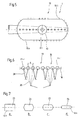
- FIG. 5 shows a device 1 with an overflow 19 which consists of a large number of individual overflows 19.1 to 19.n which are arranged in the center of the outlet opening 16 for the gas-free suspension 2.1.
- the overflow 19 provided in the outer wall of the container is also possible for the overflow 19 provided in the outer wall of the container to be attached to the container essentially all the way round, as is indicated in the figure by the lines lying on the outside in the end region. It should generally be noted that the arrangement of the individual overflows does not necessarily have to be in the center of the outlet opening for the gas-free suspension, but this central arrangement brings with it hydraulic advantages.
- FIG. 6 shows a view of individual overflows 19.1 to 19.n according to FIG. 5.
- the overflow 19 consists of several individual overflows 19.1 to 19.n, which have preferred overflow surfaces 23.1 to 23.n.
- the preferred overflow surfaces 23.1 to 23.n are circles, which are preferably formed at regular intervals A (divisions) from one another along a center line M in the outer wall 3b of the container.
- the individual overflows 19.1 to 19.n open individually or in groups (24) or sections (25) directly by means of at least one overflow pipe, not shown, or by means of at least one in the outer wall of the container by means of at least one overflow chamber designed as a half-shell and not shown, and at least one downstream and not shown Overflow pipe into the overflow system, which is preferably arranged below the container, not shown, and not shown.
- FIGS. 7a to 7d show different forms of overflow surfaces 23 according to the invention.
- the overflow surface 23 of the individual overflow 19.1 to 19.n has the shape of a rectangle (FIG. 7a), a circle, an oval or a regular or an irregular polygon (FIGS. 7b to 7d).
- the device according to the invention for degassing suspension, in particular of fiber suspension is ideally suited for implementation of the inventive method for degassing suspension, in particular of fiber suspension.
- the invention is a method and a device of the type mentioned is created, with which the Overflow for the separated, excess suspension in a fluidic optimal position and shape between the supply of suspension and Removal of gas-free suspension with further improvement of the hydraulics and can be arranged at low device cost.
Landscapes
- Chemical & Material Sciences (AREA)
- Chemical Kinetics & Catalysis (AREA)
- Engineering & Computer Science (AREA)
- Mechanical Engineering (AREA)
- Paper (AREA)
- Spinning Methods And Devices For Manufacturing Artificial Fibers (AREA)
Applications Claiming Priority (2)
| Application Number | Priority Date | Filing Date | Title |
|---|---|---|---|
| DE10131982 | 2001-07-02 | ||
| DE10131982A DE10131982A1 (de) | 2001-07-02 | 2001-07-02 | Verfahren und Vorrichtung zum Entgasen von Suspension, insbesondere Faserstoffsuspension |
Publications (3)
| Publication Number | Publication Date |
|---|---|
| EP1273697A2 true EP1273697A2 (fr) | 2003-01-08 |
| EP1273697A3 EP1273697A3 (fr) | 2003-07-23 |
| EP1273697B1 EP1273697B1 (fr) | 2006-01-18 |
Family
ID=7690306
Family Applications (1)
| Application Number | Title | Priority Date | Filing Date |
|---|---|---|---|
| EP02013117A Expired - Lifetime EP1273697B1 (fr) | 2001-07-02 | 2002-06-14 | Dispositif de dégazage de suspension, notamment de suspension fibreuse |
Country Status (4)
| Country | Link |
|---|---|
| US (1) | US7101418B2 (fr) |
| EP (1) | EP1273697B1 (fr) |
| AT (1) | ATE316167T1 (fr) |
| DE (2) | DE10131982A1 (fr) |
Cited By (4)
| Publication number | Priority date | Publication date | Assignee | Title |
|---|---|---|---|---|
| EP1479425A1 (fr) * | 2003-05-20 | 2004-11-24 | Voith Paper Patent GmbH | Installation de purification et de dégazage de suspension fibreuse |
| WO2012038245A1 (fr) * | 2010-09-21 | 2012-03-29 | Voith Patent Gmbh | Dégazage |
| DE102011087068A1 (de) | 2011-11-25 | 2013-05-29 | Voith Patent Gmbh | Überlauf |
| AT15767U1 (de) * | 2016-02-29 | 2018-05-15 | Voith Patent Gmbh | Entgasungsvorrichtung |
Families Citing this family (2)
| Publication number | Priority date | Publication date | Assignee | Title |
|---|---|---|---|---|
| RU2711264C1 (ru) * | 2016-09-01 | 2020-01-16 | Эссити Хайджин Энд Хелт Актиеболаг | Способ и устройство для влажной укладки нетканых материалов |
| SE545391C2 (en) * | 2021-05-12 | 2023-07-25 | Valmet Oy | Water and air separation device for removing air from a whitewater spray |
Family Cites Families (31)
| Publication number | Priority date | Publication date | Assignee | Title |
|---|---|---|---|---|
| US3206917A (en) * | 1961-10-04 | 1965-09-21 | Clark & Vicario Corp | Deaerated stock flow control |
| US3367808A (en) | 1964-09-28 | 1968-02-06 | Illinois Tool Works | Method and apparatus for uniting articles |
| US3367868A (en) * | 1966-04-01 | 1968-02-06 | Du Pont | Rust inhibited poly(hexafluoropropylene oxide) oil compositions |
| US3538680A (en) * | 1967-12-29 | 1970-11-10 | Clark & Vicario Corp | Papermaking apparatus and process |
| US3720315A (en) * | 1971-01-18 | 1973-03-13 | Clark & Vicario Corp | Stabilizing papermaking system cleaner operation |
| CH612491A5 (fr) * | 1976-09-23 | 1979-07-31 | Sulzer Ag | |
| SE409128B (sv) * | 1977-11-24 | 1979-07-30 | Celleco Ab | Sett att avgasa pappersmeld och anordning for genomforande av settet |
| US4219340A (en) * | 1978-12-14 | 1980-08-26 | Clark & Vicario Corporation | Method and apparatus for outflowing liquids from chamber maintained under vacuum |
| US4238206A (en) * | 1979-03-05 | 1980-12-09 | Columbia Gas System Service Corporation | Using solvents for acidic gas removal |
| DE3028428A1 (de) * | 1980-07-26 | 1982-03-04 | J.M. Voith Gmbh, 7920 Heidenheim | Siebteil einer maschine zum herstellen einer faserstoffbahn |
| FI63613C (fi) * | 1981-06-05 | 1983-07-11 | Enso Gutzeit Oy | Anordning foer avlaegsnande av gas fraon pappersmassasuspension |
| DE3469190D1 (en) * | 1983-11-08 | 1988-03-10 | Holzer Walter | Process and apparatus for separating, for example, copper from a liquid electrolyte introduced into a pluricellular electrolyser |
| FI81397C (fi) * | 1988-07-12 | 1990-10-10 | Ahlstroem Oy | Foerfarande och anordning foer avlaegsnande av laett material ur en fibersuspension. |
| DE4106140C2 (de) * | 1991-02-27 | 1994-11-24 | Escher Wyss Gmbh | Vorrichtung und deren Anwendung zur Entlüftung einer Papierstoffsuspension |
| FI93314C (fi) * | 1991-10-16 | 1995-03-27 | Ahlstroem Oy | Kaasunerotussäiliö |
| EP0556551B1 (fr) * | 1992-02-21 | 1996-10-23 | J.M. Voith GmbH | Dispositif à rouleaux pour l'application d'une couleur d'enduction sur une bande de papier |
| US5236475A (en) * | 1992-11-19 | 1993-08-17 | Lake Superior Paper Industries | Papermaking apparatus including baffles |
| US5616245A (en) * | 1994-06-07 | 1997-04-01 | Hjs Clem Ag | High gravity separator |
| FI95660C (fi) * | 1994-06-10 | 1998-07-14 | Ahlstrom Machinery Oy | Kiekkosuodattimen syöttölaite |
| US5514269A (en) * | 1994-07-27 | 1996-05-07 | Phoenix Precision Graphics, Inc. | Dual separator purification system |
| FI100950B (fi) * | 1995-10-24 | 1998-03-31 | Andritz Ahlstrom Oy | Kaasunerotussäiliö ja sen käyttö |
| GB9607843D0 (en) * | 1996-04-16 | 1996-06-19 | Pet Mate Ltd | Water treatment |
| DE19644253A1 (de) * | 1996-10-24 | 1998-05-07 | Steag Micro Tech Gmbh | Vorrichtung zum Behandeln von Substraten |
| US5868905A (en) * | 1997-04-23 | 1999-02-09 | Voith Sulzer Paper Technology North Amrica Inc. | Paper-making machine including a deaerator for a fiber suspension |
| FI103519B (fi) * | 1998-01-30 | 1999-07-15 | Valmet Corp | Laite kaasun poistamiseksi massakuituja sisältävästä vesisuspensiosta |
| US6192831B1 (en) * | 1998-07-17 | 2001-02-27 | A/S L. Frandsen | Automatic feeder |
| US6193938B1 (en) * | 1999-03-17 | 2001-02-27 | Wedeco Ag Water Technology | Device for treating liquids with UV-radiation |
| DE19946575A1 (de) | 1999-09-29 | 2001-04-05 | Voith Paper Patent Gmbh | Vorrichtung zum Entgasen von Faserstoffsuspension |
| DE19952129A1 (de) * | 1999-10-29 | 2001-05-03 | Voith Paper Patent Gmbh | Verfahren und Vorrichtung zur Entgasung einer Papierstoffsuspension |
| DE20008711U1 (de) * | 2000-05-16 | 2000-08-03 | Voith Sulzer Papiertechnik Patent GmbH, 89522 Heidenheim | Vorrichtung zum Entgasen von Faserstoffsuspension |
| DE10117037A1 (de) | 2001-04-05 | 2002-10-17 | Infineon Technologies Ag | Speicherzellenarray mit einzeln adressierbaren Speicherzellen und Verfahren zur Herstellung desselben |
-
2001
- 2001-07-02 DE DE10131982A patent/DE10131982A1/de not_active Withdrawn
-
2002
- 2002-06-14 AT AT02013117T patent/ATE316167T1/de not_active IP Right Cessation
- 2002-06-14 DE DE50205623T patent/DE50205623D1/de not_active Expired - Fee Related
- 2002-06-14 EP EP02013117A patent/EP1273697B1/fr not_active Expired - Lifetime
- 2002-06-28 US US10/185,168 patent/US7101418B2/en not_active Expired - Fee Related
Cited By (6)
| Publication number | Priority date | Publication date | Assignee | Title |
|---|---|---|---|---|
| EP1479425A1 (fr) * | 2003-05-20 | 2004-11-24 | Voith Paper Patent GmbH | Installation de purification et de dégazage de suspension fibreuse |
| US7214257B2 (en) | 2003-05-20 | 2007-05-08 | Voith Paper Patent Gmbh | Plant for cleaning and degassing a fibrous suspension |
| WO2012038245A1 (fr) * | 2010-09-21 | 2012-03-29 | Voith Patent Gmbh | Dégazage |
| DE102011087068A1 (de) | 2011-11-25 | 2013-05-29 | Voith Patent Gmbh | Überlauf |
| WO2013075995A1 (fr) | 2011-11-25 | 2013-05-30 | Voith Patent Gmbh | Dispositif de dégazage avec trop-plein |
| AT15767U1 (de) * | 2016-02-29 | 2018-05-15 | Voith Patent Gmbh | Entgasungsvorrichtung |
Also Published As
| Publication number | Publication date |
|---|---|
| DE10131982A1 (de) | 2003-01-16 |
| US20030015304A1 (en) | 2003-01-23 |
| ATE316167T1 (de) | 2006-02-15 |
| US7101418B2 (en) | 2006-09-05 |
| EP1273697B1 (fr) | 2006-01-18 |
| EP1273697A3 (fr) | 2003-07-23 |
| DE50205623D1 (de) | 2006-04-06 |
Similar Documents
| Publication | Publication Date | Title |
|---|---|---|
| DE4106140C2 (de) | Vorrichtung und deren Anwendung zur Entlüftung einer Papierstoffsuspension | |
| DE69618670T2 (de) | Entlüftungsbehälter | |
| DE2950194C2 (de) | Vorrichtung zum Sammeln einer Flüssigkeit an einem ersten Ort und zum Fördern der Flüssigkeit an einen anderen unterhalb des ersten Orts liegenden zweiten Ort | |
| EP1273697A2 (fr) | Dispositif de dégazage de suspension, notamment de suspension fibreuse | |
| EP1143066A2 (fr) | Dispositif de dégazage de suspension fibreuse | |
| DE19733059C2 (de) | Verfahren und Vorrichtung zur Entfernung von Feststoffen aus einer wässrigen Faserstoffsuspension | |
| EP1091040B1 (fr) | Dispositif de dégazage de suspensions fibreuses | |
| DE2532528C3 (de) | Verfahren zur Einstellung eines bestimmten Verteilungsgesetzes des Durchflusses in einem Mediumsstrom, Vorrichtung zur Durchführung des Verfahrens und Verwendung des Verfahrens bzw. der Vorrichtung | |
| EP2491176B1 (fr) | Procede pour eliminer des particules solides d'une suspension fibreuse par flottation | |
| DE69816940T2 (de) | Verbesserter reaktor zur flüssigkeitsreinigung | |
| EP1001078B1 (fr) | Méthode et dispositif pour la séparation des particules d'une suspension aqueuse de fibres à papier | |
| DE3101221A1 (de) | "einrichtung zur schaumflotation" | |
| DE10329883B4 (de) | Verfahren zur Flotation von Störstoffen aus einer wässrigen Papierfasersuspension | |
| DE4417461C2 (de) | Zentralverteiler | |
| DE69408766T2 (de) | Vorrichtung und Verfahren zum Entgasen eines Hydraulikkreislaufs | |
| DE3401161C2 (fr) | ||
| DE3620999A1 (de) | Vorrichtung zur entfernung von blasen | |
| DE202012013019U1 (de) | Schaumrückführung | |
| DE102018208316A1 (de) | Ansaugkammer für eine Betriebsmittelpumpe, Betriebsmittelpumpe sowie Betriebsmittelbehälter | |
| DE19946575A1 (de) | Vorrichtung zum Entgasen von Faserstoffsuspension | |
| CH670051A5 (fr) | ||
| DE2045920C3 (de) | Vorrichtung zur Bildung einer Fasersuspension für die Herstellung von Langfaserstoff-Bahnen | |
| DE19852549C2 (de) | Verfahren und Vorrichtung zur Entfernung von Partikeln aus einer wässrigen papierfaserhaltigen Suspension | |
| DE202025107460U1 (de) | Ölflotationstank | |
| EP1424116A1 (fr) | Dispositif de dégazage. |
Legal Events
| Date | Code | Title | Description |
|---|---|---|---|
| PUAI | Public reference made under article 153(3) epc to a published international application that has entered the european phase |
Free format text: ORIGINAL CODE: 0009012 |
|
| AK | Designated contracting states |
Kind code of ref document: A2 Designated state(s): AT BE CH CY DE DK ES FI FR GB GR IE IT LI LU MC NL PT SE TR |
|
| AX | Request for extension of the european patent |
Free format text: AL;LT;LV;MK;RO;SI |
|
| PUAL | Search report despatched |
Free format text: ORIGINAL CODE: 0009013 |
|
| AK | Designated contracting states |
Designated state(s): AT BE CH CY DE DK ES FI FR GB GR IE IT LI LU MC NL PT SE TR |
|
| AX | Request for extension of the european patent |
Extension state: AL LT LV MK RO SI |
|
| 17P | Request for examination filed |
Effective date: 20040123 |
|
| AKX | Designation fees paid |
Designated state(s): AT DE FI IT SE |
|
| GRAP | Despatch of communication of intention to grant a patent |
Free format text: ORIGINAL CODE: EPIDOSNIGR1 |
|
| GRAS | Grant fee paid |
Free format text: ORIGINAL CODE: EPIDOSNIGR3 |
|
| GRAA | (expected) grant |
Free format text: ORIGINAL CODE: 0009210 |
|
| AK | Designated contracting states |
Kind code of ref document: B1 Designated state(s): AT DE FI IT SE |
|
| PG25 | Lapsed in a contracting state [announced via postgrant information from national office to epo] |
Ref country code: IT Free format text: LAPSE BECAUSE OF FAILURE TO SUBMIT A TRANSLATION OF THE DESCRIPTION OR TO PAY THE FEE WITHIN THE PRESCRIBED TIME-LIMIT;WARNING: LAPSES OF ITALIAN PATENTS WITH EFFECTIVE DATE BEFORE 2007 MAY HAVE OCCURRED AT ANY TIME BEFORE 2007. THE CORRECT EFFECTIVE DATE MAY BE DIFFERENT FROM THE ONE RECORDED. Effective date: 20060118 |
|
| REF | Corresponds to: |
Ref document number: 50205623 Country of ref document: DE Date of ref document: 20060406 Kind code of ref document: P |
|
| REG | Reference to a national code |
Ref country code: SE Ref legal event code: TRGR |
|
| RAP2 | Party data changed (patent owner data changed or rights of a patent transferred) |
Owner name: VOITH PATENT GMBH |
|
| PLBE | No opposition filed within time limit |
Free format text: ORIGINAL CODE: 0009261 |
|
| STAA | Information on the status of an ep patent application or granted ep patent |
Free format text: STATUS: NO OPPOSITION FILED WITHIN TIME LIMIT |
|
| 26N | No opposition filed |
Effective date: 20061019 |
|
| PGFP | Annual fee paid to national office [announced via postgrant information from national office to epo] |
Ref country code: SE Payment date: 20070614 Year of fee payment: 6 |
|
| PGFP | Annual fee paid to national office [announced via postgrant information from national office to epo] |
Ref country code: FI Payment date: 20070615 Year of fee payment: 6 |
|
| PGFP | Annual fee paid to national office [announced via postgrant information from national office to epo] |
Ref country code: AT Payment date: 20070618 Year of fee payment: 6 |
|
| PGFP | Annual fee paid to national office [announced via postgrant information from national office to epo] |
Ref country code: DE Payment date: 20070622 Year of fee payment: 6 |
|
| EUG | Se: european patent has lapsed | ||
| PG25 | Lapsed in a contracting state [announced via postgrant information from national office to epo] |
Ref country code: FI Free format text: LAPSE BECAUSE OF NON-PAYMENT OF DUE FEES Effective date: 20080614 |
|
| PG25 | Lapsed in a contracting state [announced via postgrant information from national office to epo] |
Ref country code: DE Free format text: LAPSE BECAUSE OF NON-PAYMENT OF DUE FEES Effective date: 20090101 Ref country code: AT Free format text: LAPSE BECAUSE OF NON-PAYMENT OF DUE FEES Effective date: 20080614 |
|
| PG25 | Lapsed in a contracting state [announced via postgrant information from national office to epo] |
Ref country code: SE Free format text: LAPSE BECAUSE OF NON-PAYMENT OF DUE FEES Effective date: 20080615 |