EP1273709A2 - Ensemble de fixation d' un rail de voie ferrée - Google Patents
Ensemble de fixation d' un rail de voie ferrée Download PDFInfo
- Publication number
- EP1273709A2 EP1273709A2 EP02022626A EP02022626A EP1273709A2 EP 1273709 A2 EP1273709 A2 EP 1273709A2 EP 02022626 A EP02022626 A EP 02022626A EP 02022626 A EP02022626 A EP 02022626A EP 1273709 A2 EP1273709 A2 EP 1273709A2
- Authority
- EP
- European Patent Office
- Prior art keywords
- clip
- anchoring
- anchoring device
- rail fastening
- leg
- Prior art date
- Legal status (The legal status is an assumption and is not a legal conclusion. Google has not performed a legal analysis and makes no representation as to the accuracy of the status listed.)
- Withdrawn
Links
- 238000004873 anchoring Methods 0.000 claims abstract description 73
- 230000000717 retained effect Effects 0.000 claims description 3
- 238000009434 installation Methods 0.000 claims description 2
- 229910000831 Steel Inorganic materials 0.000 description 3
- 239000010959 steel Substances 0.000 description 3
- 241001669679 Eleotris Species 0.000 description 2
- 238000005266 casting Methods 0.000 description 2
- 238000003780 insertion Methods 0.000 description 2
- 230000037431 insertion Effects 0.000 description 2
- 239000012212 insulator Substances 0.000 description 2
- 239000002184 metal Substances 0.000 description 2
- 238000005452 bending Methods 0.000 description 1
- 230000001419 dependent effect Effects 0.000 description 1
- 238000007373 indentation Methods 0.000 description 1
- 239000012858 resilient material Substances 0.000 description 1
Images



Classifications
-
- E—FIXED CONSTRUCTIONS
- E01—CONSTRUCTION OF ROADS, RAILWAYS, OR BRIDGES
- E01B—PERMANENT WAY; PERMANENT-WAY TOOLS; MACHINES FOR MAKING RAILWAYS OF ALL KINDS
- E01B9/00—Fastening rails on sleepers, or the like
- E01B9/02—Fastening rails, tie-plates, or chairs directly on sleepers or foundations; Means therefor
- E01B9/28—Fastening on wooden or concrete sleepers or on masonry with clamp members
- E01B9/30—Fastening on wooden or concrete sleepers or on masonry with clamp members by resilient steel clips
-
- E—FIXED CONSTRUCTIONS
- E01—CONSTRUCTION OF ROADS, RAILWAYS, OR BRIDGES
- E01B—PERMANENT WAY; PERMANENT-WAY TOOLS; MACHINES FOR MAKING RAILWAYS OF ALL KINDS
- E01B9/00—Fastening rails on sleepers, or the like
- E01B9/02—Fastening rails, tie-plates, or chairs directly on sleepers or foundations; Means therefor
- E01B9/28—Fastening on wooden or concrete sleepers or on masonry with clamp members
- E01B9/30—Fastening on wooden or concrete sleepers or on masonry with clamp members by resilient steel clips
- E01B9/303—Fastening on wooden or concrete sleepers or on masonry with clamp members by resilient steel clips the clip being a shaped bar
Definitions
- the present invention relates to a railway rail fastening assembly.
- a common system for fastening a railway rail to an underlying foundation comprises a pair of anchoring devices secured to the foundation on either side of the rail when it is in position, which devices retain the anchoring legs of respective resilient rail fastening clips which bear down on the rail.
- a railway rail fastening clip (known as an "e"-clip) comprising (in one version) a rod of resilient material bent so as to have, proceeding from one free end of the rod to the other free end thereof, firstly a straight anchoring leg, secondly a reverse bend portion, thirdly a portion beside the anchoring leg forming a "heel”, fourthly another reverse bend portion and finally another portion beside the anchoring leg forming a "toe”.
- This version of the clip is referred to hereafter as a "right-handed” clip.
- the clip is a mirror image of a "right-handed” clip, made such that the anchoring leg may be inserted into the opposite end of the anchoring device.
- a railway rail fastening assembly for fastening a railway rail to an underlying foundation, the assembly comprising a resilient railway rail fastening clip and a rail fastening clip anchoring device, characterised in that the clip has thereon stop means, for engaging cooperating means provided on the rail fastening clip anchoring device, whereby overdriving of the clip into the said anchoring device is prevented, the said stop means comprising one of an abutment surface and a projection and the said cooperating means comprising the other of the abutment surface and the projection.
- a clip can be correctly positioned within the housing of an anchoring device.
- the abutment surface may be provided by a face of a recess, which is desirably inclined with respect to the direction of installation of the clip by an angle in the range from 35° to 90°.
- the preferred angle is about 90°.
- the said stop means may be provided on the anchoring leg and the cooperating means may be provided inside the housing of the anchoring device.
- the clip to which the invention is applied is preferably, but not essentially, an "e"-clip or "PR" clip. It should be noted that there is no need to make any adjustments to the overall shape of such clips, for example to lengthen the anchoring legs thereof, in order to apply the invention thereto.
- the prior art resilient railway rail fastening clip 10 shown in Figure 1 is a type of "e"-clip.
- the clip 10 is made by bending a metal rod so as to have, proceeding from one end A of the rod to the other end B, a substantially straight first portion or anchoring leg 11, then a second reverse bend portion 12, then a third portion 13, then a fourth reverse bend portion 14, and finally a fifth portion 15.
- the clip 10 is in the configuration shown, such that the lowermost points on the third and fifth portions are in the same plane and the clip 10 is viewed from directly above or below that plane, the third and fifth portions appear to lie on opposite sides of the first portion 11.
- the so-called "PR"-clip is of a similar shape.
- Both the "e”-clip and the “PR”-clip may be retained, such that the "toe” of the clip (either the third portion 13 or the fifth portion 15) bears on an adjoining rail, by a cast metal rail fastening clip anchoring device or shoulder 100 such as shown in Figure 1B.
- a cast metal rail fastening clip anchoring device or shoulder 100 such as shown in Figure 1B. Only one of the pair of anchoring devices 100 which would be used in the rail fastening assembly is illustrated in Figure 1B.
- the anchoring device 100 is secured to a rail foundation, in this case a concrete sleeper 2, by means of a leg 101 embedded in the concrete.
- the leg 101 is joined to a housing 102 of the anchoring device 100, which housing 102 has a passageway 103 therethrough.
- a rail 1 having a foot 1a is positioned on a cushioning rail pad 4 between the pair of shoulders 100 and a rail insulator 3 is placed on the rail foot 1a.
- the anchoring leg 11 of the rail clip 10 is then driven into the passageway 103, deflecting the clip 10 such that the "toe” portion of the clip (in this case the fifth portion 15) exerts a desired force on the foot 1a of the rail 1 through the rail insulator 3.
- the "heel” portion (in this case the third portion 13) of the clip 10 comes to rest on a ledge portion 104 of the housing 102.
- An upper surface of the anchoring leg 11 is held in contact with the roof of the passageway 103.
- anchoring leg 11 of the clip 10 may be chamfered at its free end so as to facilitate insertion of the anchoring leg 11 into the passageway 103 of the anchoring device 100.
- Figures 2 and 3 show clips and anchoring devices which are the subject of co-pending European patent application no. 98932355.5, which do not embody, but are useful for understanding, the present invention.
- FIG. 2 shows an anchoring leg 21 of a rail fastening clip 20.
- the rail fastening clip 20 is not shown in its entirety, but other than its anchoring leg 21 could be similar to, for example, an "e"-clip, a "PR"-clip or the like.
- the anchoring leg 21 has a chamfer 21b at its free end A and, spaced from the free end A, first locating means comprising a detent or recess 21a having an abutment surface 21c.
- An anchoring device or shoulder 200 (not shown in its entirety) for retaining the rail fastening clip 20 has a housing 202 formed therethrough with a passageway 203. Inside the passageway 203, on the roof thereof, are second locating means comprising a projection 203a.
- the first and second locating means cooperate together to provide means for resisting unauthorised removal of the clip 20 from the anchoring device 200.
- the remainder of the anchoring device 200 could be similar to the anchoring device 100 shown in Figure 1B
- the detent 21a may be stamped onto the anchoring leg of the clip 20, during or after forming of the clip, and the projection 203a is formed during forming of the anchoring device 200.
- the clip and anchoring device shown in Figure 3 differ from those of Figure 2 in that the rail fastening clip 30 (not shown in its entirety) has an anchoring leg 31 with chamfer 31b having first locating means comprising a projection 31a and the anchoring device 300 (not shown in its entirety) has a housing 302 with a passageway 303 formed on a roof thereof with second locating means comprising a recess 303a having an abutment surface 303b.
- An anchoring device embodying the present invention may be made by a casting process, but may also comprise a pressed steel anchoring device, for example as described below with reference to Figs. 4A, 4B, 5A and 5B, or to a rolled steel plate (not shown).
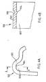
- a pressed steel anchoring device 500 has a housing 502 formed so as to have a passageway 503 therethrough.
- the roof of the passageway 503 is provided, at a position adjacent to but spaced from one end of the passageway 503, with a projection 504 made by forming an indentation 505 on the top of the housing 502.
- the projection 504 can be seen more clearly in Fig. 4B, which shows a cross-sectional view of the top of the housing 502 parallel to the passageway 503.
- the shape and dimensions of the projection 504 are dependent upon the shape and dimensions of the abutment surface with which it is to cooperate.
- the projection 504 may be formed at a distance of 45mm from one end of the passageway 503 so as to have a width of 5mm, a height of 2mm and a radius of curvature of 3mm.
- FIGs 5A and 5B show the anchoring leg 51 of a rail fastening clip 50 (not shown in its entirety) of an assembly embodying the present invention, which clip is similar in many respects to the clips of Figures 2 and 3.
- the anchoring leg 51 has a chamfer 51b formed at its free end A and, spaced a short distance from the free end A, a detent or recess 51a.
- the recess 51a has two abutment faces 51c and 51d, respectively extending downwardly and upwardly (proceeding along the anchoring leg 51 away from the free end A).
- the upwardly-extending face 51d is steeper than the downwardly-extending face 51c; in the example shown the angle of inclination with respect to the longitudinal axis of the anchoring leg 51 is about 30° for the downwardly-extending face 51c and about 90° towards the top of the upwardly-extending face 51d, the bottom of which has a radius of 1R.
- the recess 51a may be formed so that the edge nearest the end A of the leg 51 is 10mm therefrom and so as to be 12.5mm long (in the direction in which the leg 51 extends) and 2mm deep.
- the radius at the foot of the upwardly-extending face 51d is 1mm.
- the angle of inclination of the upwardly-extending face 51d can also be varied, but in the embodiment of Figures 4A, 4B, 5A and 5B it has been chosen so as to provide a stop which comes up against the projection 504 when the clip 50 is driven into the anchoring device 500, thereby ensuring that the clip 50 cannot easily be driven beyond its nominal installed position in which the clip sits in its intended working position.
- a suitably steep upwardly-extending face 51d for example at an angle with respect to the longitudinal axis of the anchoring leg 51 in the range form 35° to 90°, the clip driving force required increases sharply when the clip reaches the correct position, thus preventing overdriving of the clip.
- a clip embodying the present invention provided on its anchoring leg with a detent (rather than a projection) can be used with existing anchoring devices, not embodying the present invention, thereby allowing the railway to maintain stocks of only one type of clip, which can be used with additional benefits in anchoring devices embodying the invention, but also without disadvantage as compared to conventional clips in existing anchoring devices which do not embody the invention.
Landscapes
- Engineering & Computer Science (AREA)
- Mechanical Engineering (AREA)
- Architecture (AREA)
- Civil Engineering (AREA)
- Structural Engineering (AREA)
- Railway Tracks (AREA)
- Connection Of Plates (AREA)
- Braking Arrangements (AREA)
- Machines For Laying And Maintaining Railways (AREA)
- Clamps And Clips (AREA)
Applications Claiming Priority (5)
| Application Number | Priority Date | Filing Date | Title |
|---|---|---|---|
| GB9714899 | 1997-07-15 | ||
| GB9714899A GB2327230A (en) | 1997-07-15 | 1997-07-15 | Resilient railway rail fastening clip and rail fastening clip anchoring device |
| GB9810241 | 1998-05-13 | ||
| GB9810241A GB2329921B (en) | 1997-07-15 | 1998-05-13 | Resilient railway rail fastening clips and associated rail fastening clip anchoring devices |
| EP98932355A EP0996789B1 (fr) | 1997-07-15 | 1998-07-02 | Attaches elastiques de fixation de rails de voie ferree et dispositifs associes d'ancrage d'attaches de fixation de rail |
Related Parent Applications (1)
| Application Number | Title | Priority Date | Filing Date |
|---|---|---|---|
| EP98932355A Division EP0996789B1 (fr) | 1997-07-15 | 1998-07-02 | Attaches elastiques de fixation de rails de voie ferree et dispositifs associes d'ancrage d'attaches de fixation de rail |
Publications (2)
| Publication Number | Publication Date |
|---|---|
| EP1273709A2 true EP1273709A2 (fr) | 2003-01-08 |
| EP1273709A3 EP1273709A3 (fr) | 2003-01-22 |
Family
ID=10815891
Family Applications (1)
| Application Number | Title | Priority Date | Filing Date |
|---|---|---|---|
| EP02022626A Withdrawn EP1273709A3 (fr) | 1997-07-15 | 1998-07-02 | Ensemble de fixation d' un rail de voie ferrée |
Country Status (4)
| Country | Link |
|---|---|
| EP (1) | EP1273709A3 (fr) |
| KR (1) | KR100587828B1 (fr) |
| GB (2) | GB2327230A (fr) |
| MY (1) | MY122114A (fr) |
Families Citing this family (2)
| Publication number | Priority date | Publication date | Assignee | Title |
|---|---|---|---|---|
| KR20000021701A (ko) * | 1998-09-30 | 2000-04-25 | 허영준 | 철도레일고정조립체 |
| GB2435285A (en) * | 2006-02-21 | 2007-08-22 | Pandrol Ltd | Fastening railway rails |
Citations (2)
| Publication number | Priority date | Publication date | Assignee | Title |
|---|---|---|---|---|
| GB861473A (en) | 1956-08-03 | 1961-02-22 | Lockspike Ltd | Improvements in fastening members for anchoring railway rails and in rail-fastening arrangements employing such members |
| GB1510224A (en) | 1975-11-07 | 1978-05-10 | Pandrol Ltd | Railway rail fastening clip and a railway rail-and-fastening assembly employing it |
Family Cites Families (7)
| Publication number | Priority date | Publication date | Assignee | Title |
|---|---|---|---|---|
| US2265745A (en) * | 1941-03-12 | 1941-12-09 | George H Roscoe | Rail fastener |
| CH354801A (fr) * | 1959-05-04 | 1961-06-15 | Lockspike Ltd | Dispositif de fixation d'un rail de chemin de fer |
| GB1519875A (en) * | 1977-01-24 | 1978-08-02 | Pandrol Ltd | Rail fastenings |
| FR2436848A1 (fr) * | 1978-05-22 | 1980-04-18 | Ferroviaires Soc | Dispositif d'attache elastique de voies ferrees |
| GB2085057B (en) * | 1980-09-29 | 1984-05-16 | Pandrol Ltd | A rail clip and an assembly on a railway track which includes the clip |
| US4832261A (en) * | 1987-02-09 | 1989-05-23 | Chemetron-Railway Products, Inc. | Railway rail fastening assembly |
| IN185923B (fr) * | 1991-12-18 | 2001-05-19 | Pandrol Ltd |
-
1997
- 1997-07-15 GB GB9714899A patent/GB2327230A/en not_active Withdrawn
-
1998
- 1998-05-13 GB GB9810241A patent/GB2329921B/en not_active Expired - Fee Related
- 1998-07-02 KR KR1020007000489A patent/KR100587828B1/ko not_active Expired - Fee Related
- 1998-07-02 EP EP02022626A patent/EP1273709A3/fr not_active Withdrawn
- 1998-07-08 MY MYPI98003114A patent/MY122114A/en unknown
Patent Citations (2)
| Publication number | Priority date | Publication date | Assignee | Title |
|---|---|---|---|---|
| GB861473A (en) | 1956-08-03 | 1961-02-22 | Lockspike Ltd | Improvements in fastening members for anchoring railway rails and in rail-fastening arrangements employing such members |
| GB1510224A (en) | 1975-11-07 | 1978-05-10 | Pandrol Ltd | Railway rail fastening clip and a railway rail-and-fastening assembly employing it |
Also Published As
| Publication number | Publication date |
|---|---|
| GB2329921B (en) | 2001-07-04 |
| GB2329921A (en) | 1999-04-07 |
| GB2327230A (en) | 1999-01-20 |
| GB9714899D0 (en) | 1997-09-17 |
| MY122114A (en) | 2006-03-31 |
| KR100587828B1 (ko) | 2006-06-13 |
| EP1273709A3 (fr) | 2003-01-22 |
| HK1016669A1 (en) | 1999-11-05 |
| GB9810241D0 (en) | 1998-07-08 |
| KR20010021925A (ko) | 2001-03-15 |
Similar Documents
| Publication | Publication Date | Title |
|---|---|---|
| EP1987199B1 (fr) | Attache de fixation de rail ferroviaire | |
| JP3187050B2 (ja) | 鉄道レール係留クリップおよびアセンブリ、ならびに同クリップおよび同アセンブリの使用方法 | |
| EP0050048A1 (fr) | Ancrage d'un organe de fixation d'un rail de chemin de fer sur un support de rail | |
| CS235058B2 (en) | Clamp for fastening of railway rail | |
| CN103328725B (zh) | 铁轨紧固扣件和绝缘子 | |
| EP1273709A2 (fr) | Ensemble de fixation d' un rail de voie ferrée | |
| GB2358034A (en) | A railway rail fastening assembly | |
| US4981264A (en) | Device for fixing stock rails in railway switches as well as process for fixing stock rails by means of such device | |
| CA2781470C (fr) | Ancre permettant de lever une piece en beton | |
| WO2010063062A1 (fr) | Collier pour une ancre de levage de béton | |
| US8888012B2 (en) | Insulator for railway fastening clip and railway rail fastening clip for use therewith | |
| US4150792A (en) | Rail fastener | |
| US4572701A (en) | Universal concrete screed system | |
| JP3058594B2 (ja) | 高さ調整機能付レール締結装置 | |
| EP1294985B1 (fr) | Attache de rail de voie ferree et plaque de base pour ensemble de fixation de rail de voie ferree | |
| JPH046802B2 (fr) | ||
| HK1122080B (en) | Railway rail fastening clip |
Legal Events
| Date | Code | Title | Description |
|---|---|---|---|
| PUAI | Public reference made under article 153(3) epc to a published international application that has entered the european phase |
Free format text: ORIGINAL CODE: 0009012 |
|
| PUAL | Search report despatched |
Free format text: ORIGINAL CODE: 0009013 |
|
| AC | Divisional application: reference to earlier application |
Ref document number: 996789 Country of ref document: EP |
|
| AK | Designated contracting states |
Kind code of ref document: A2 Designated state(s): FR |
|
| AK | Designated contracting states |
Kind code of ref document: A3 Designated state(s): FR |
|
| RIC1 | Information provided on ipc code assigned before grant |
Free format text: 7E 01B 9/48 A, 7E 01B 9/30 B |
|
| AKX | Designation fees paid | ||
| STAA | Information on the status of an ep patent application or granted ep patent |
Free format text: STATUS: THE APPLICATION IS DEEMED TO BE WITHDRAWN |
|
| 18D | Application deemed to be withdrawn |
Effective date: 20030723 |