EP1273719A1 - Procede et appareil permettant de transmettre des donnees de fonctionnement de machine - Google Patents
Procede et appareil permettant de transmettre des donnees de fonctionnement de machine Download PDFInfo
- Publication number
- EP1273719A1 EP1273719A1 EP01915666A EP01915666A EP1273719A1 EP 1273719 A1 EP1273719 A1 EP 1273719A1 EP 01915666 A EP01915666 A EP 01915666A EP 01915666 A EP01915666 A EP 01915666A EP 1273719 A1 EP1273719 A1 EP 1273719A1
- Authority
- EP
- European Patent Office
- Prior art keywords
- operation data
- controller
- working machine
- control station
- predetermined time
- Prior art date
- Legal status (The legal status is an assumption and is not a legal conclusion. Google has not performed a legal analysis and makes no representation as to the accuracy of the status listed.)
- Granted
Links
Images


Classifications
-
- H—ELECTRICITY
- H04—ELECTRIC COMMUNICATION TECHNIQUE
- H04M—TELEPHONIC COMMUNICATION
- H04M11/00—Telephonic communication systems specially adapted for combination with other electrical systems
-
- H—ELECTRICITY
- H04—ELECTRIC COMMUNICATION TECHNIQUE
- H04M—TELEPHONIC COMMUNICATION
- H04M11/00—Telephonic communication systems specially adapted for combination with other electrical systems
- H04M11/007—Telephonic communication systems specially adapted for combination with other electrical systems with remote control systems
-
- E—FIXED CONSTRUCTIONS
- E02—HYDRAULIC ENGINEERING; FOUNDATIONS; SOIL SHIFTING
- E02F—DREDGING; SOIL-SHIFTING
- E02F9/00—Component parts of dredgers or soil-shifting machines, not restricted to one of the kinds covered by groups E02F3/00 - E02F7/00
- E02F9/20—Drives; Control devices
-
- E—FIXED CONSTRUCTIONS
- E02—HYDRAULIC ENGINEERING; FOUNDATIONS; SOIL SHIFTING
- E02F—DREDGING; SOIL-SHIFTING
- E02F9/00—Component parts of dredgers or soil-shifting machines, not restricted to one of the kinds covered by groups E02F3/00 - E02F7/00
- E02F9/26—Indicating devices
Definitions
- This invention relates to a method and system for transmitting operation data of a working machine such as a hydraulic excavator, which automatically transmit the operation data of the working machine to a control station located at a remote plate.
- JP-A-11065645 As another conventional technique, there is, for example, the machine abnormality supervising system and method disclosed in JP-A-11065645. According to this conventional technique, when an abnormality is detected during operation of a machine such as a construction machine, data of the abnormality are automatically transmitted from the machine to a supervising station, in other words, a control station at a remote place via a communication network.
- the above-mentioned conventional techniques each automatically transmits data on abnormality to a control station located at a remote place only when the abnormality has occurred on a working machine such as a construction machine. These conventional techniques, therefore, cannot grasp operation conditions of a working machine or the like, which has not developed abnormality yet, at a control station located at a remote place although they are effective for repair work of the working machine which has developed abnormality.
- operation conditions of a working machine such as a hydraulic excavator which is performing digging work, for example, in a mountainous area can be grasped at a control station located at a remote place, it would be possible to determine a desired maintenance schedule and further, to determine suitable replacement parts to be needed upon maintenance and to collect such parts ready for use. It would, therefore, be possible to readily achieve high-accuracy maintenance management on the working machine. If operation data can be analyzed as needed, development of a working machine the performance of which is still better would be expected.
- the present invention has as an object thereof the provision of a method and system for transmitting operation data of a working machine, which make it possible to grasp operation conditions of the working machine at a control station located at a remote place no matter whether or not abnormality has occurred on the working machine.
- the present invention provides a method for automatically transmitting operation data of a working machine from a controller, which is arranged on the working machine and has produced the operation data, to a control station located at a remote place via predetermined communication means, which comprises storing the operation data at intervals of a predetermined time in the controller, and automatically transmitting at least a group of operation data out of the operation data, said group of operation data having been stored during desired one or more of the intervals, at a predetermined time point from the controller to the control station.
- the present invention also provides a method for automatically transmitting operation data of plural working machines from controllers, which are arranged on the working machines, respectively, and have produced the operation data of the corresponding working machines, to a control station located at a remote place via predetermined communication means, which comprises storing the operation data of the respective working machines at intervals of a predetermined time in their corresponding controllers, and automatically transmitting groups of operation data out of the operation data, said groups of operation data having been stored during desired ones or more of the intervals, from the controllers to the control station at predetermined time points shifted from one another.
- operation data occurred upon operation of the working machine are stored in the controller of the working machine at intervals of a predetermined time, for example, 24 hours.
- the operation data stored as described above during desired one or more of the intervals are automatically transmitted from the controller to the control station located at the remote place via the predetermined communication means at the predetermined time point, for example, when a key switch for starting the working machine is turned on or at a time designated beforehand. Accordingly, the working conditions of the working machine can be precisely grasped at the control station located at the remote place no matter whether or not abnormality has occurred on the working machine.
- it is possible to set different transmitting times for the individual working machines so that the operation data can be transmitted from the individual working machines to the control station without overlapping.
- the above-mentioned predetermined time may be set, for example, at 24 hours as mentioned above, in other words, at 1 day, and the operation data of a preceding day may be transmitted at a predetermined time point.
- the operation data of the preceding day may be transmitted only when the working machine was operated on the preceding day. This makes it possible to reduce the number of transmissions.
- the time can be set at 0:00 a.m.
- these time points may be preferably set such that operation data are transmitted from different working machines at predetermined intervals, for example, at one-minute intervals.
- the present invention also provides a system for transmitting operation data of a working machine, said system being provided with operation detecting means for detecting operating conditions of the working machine, a controller for producing, as operation data, data detected by the operation detecting means, said operation detecting means and said controller being arranged on the working machine, and a control station located at a remote place, connected with the controller via predetermined communication means and adapted to receive operation data outputted from the controller, wherein the controller comprises a clock unit, a memory unit for storing the produced operation data at predetermined time intervals on a basis of a time clocked at the clock unit and an output unit for outputting at least a group of operation data out of the operation data, said group of operation data having been stored in the memory unit during desired one or more of the intervals, at a predetermined time point, and automatically transmits to the control station the operation data outputted from the output unit of the controller.
- operation data occurred upon operation of the working machine such as a hydraulic excavator are stored in the memory unit of the controller at intervals of a predetermined time, for example, 24 hours, on the basis of a time clocked at the clock unit.
- the operation data stored in the memory unit during desired one or more of the intervals are automatically transmitted from the output unit of the controller to the control station located at the remote place via the predetermined communication means at the predetermined time point such as a time stored in the memory unit. Accordingly, the working conditions of the working machine can be precisely grasped at the control station located at the remote place no matter whether or not abnormality has occurred on the working machine.
- system may further comprise rewriting means capable of rewriting the time stored in the memory unit of the controller.
- the predetermined communication means may comprise satellite communication terminal equipment arranged on the working machine and adapted to receive the operation data outputted from the output unit of the controller, a communication satellite for receiving the operation data outputted from the satellite communication terminal equipment, and an earth station for receiving the operation data outputted from the communication satellite and outputting the operation data to the control station.
- the predetermined communication means may comprise a telephone line.
- the predetermined communication means may further comprise a cellular telephone.
- the predetermined communication means may comprise radio-communication equipment.
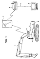
- FIGS. 1 and 2 are the diagrams illustrating the construction of the one embodiment of the system for performing the method according to the present invention for transmitting the operation data of the working machine, in which FIG. 1 is the schematic diagram illustrating the overall construction and FIG. 2 is the block diagram showing the construction of the essential part of the construction.
- a hydraulic excavator 1 is equipped with an operation detecting means 4 for detecting an operation state of the hydraulic excavator 1.
- This operation detecting means 4 comprises inter alia a key switch for detecting, for example, whether or not a key for starting the hydraulic excavator 1 has been inserted into a keyhole, and outputting a key switch signal; a regulator drive detector for detecting whether or not a regulator for controlling a delivery rate of a variable displacement hydraulic pump as a main hydraulic pump, and outputting a regulator drive signal; an engine speed sensor for detecting an actual speed of an engine, which operates the above-mentioned hydraulic pump, and outputting an engine speed signal; a delivery pressure sensor for detecting a delivery pressure of the above-mentioned hydraulic pump and outputting a pump pressure signal; a pilot pressure sensor for detecting a pilot pressure adapted to change over a directional control valve included in a hydraulic circuit, which the hydraulic excavator 1 is equipped with, and outputting a pilot
- the working machine is also equipped with a controller 3 for producing predetermined operation data in response to data detected by the operation detecting means 4 composed of the above-mentioned individual detectors and sensors, in other words, the individual signals outputted from the operation detecting means 4.
- This controller 3 includes an input unit 10 for receiving individual signals outputted from the operation detecting means 4; a clock unit 11; a memory unit 13 composed of a non-volatile memory such as EEPROM or a flash memory; a central processing unit, namely, CPU 12 having logical decision and operation functions and adapted to perform processing for the production and transmission of operation data; and an output unit 14 for outputting, in accordance with a transmission command from CPU 12, operation data produced by CPU 12.
- the operation data produced by CPU 12 are stored in the memory unit 13 at intervals of a predetermined time on the basis of the time clocked at the clock unit 11. Further, operation data stored in the memory unit 13 are outputted from the output unit 14 at a predetermined time point, for example, when the key for starting the hydraulic excavator 1 has been inserted and the key switch has been turned on or at a time stored beforehand in the memory unit 13.
- the hydraulic excavator 1 is also equipped with satellite communication terminal equipment 2 for receiving operation data signals outputted from the output unit 14 of the controller 3.
- the operation data signals outputted from the satellite transmission terminal equipment 2 are transmitted to a communication satellite 5, and are then transmitted from the communication satellite 5 to an earth station 6.
- This earth station 6 and a supervising station 8, which performs remote supervision of the above-mentioned operation state of the hydraulic excavator 1, are connected with each other via a communication line, for example, a telephone line 7.
- the above-mentioned operation data of the hydraulic excavator 1, said operation data having been processed into an electronic mail format or the like at the earth station 6, are transmitted to the control station 8 via the telephone line 7, and can be obtained at any time by a personal computer which the control station 8 is equipped with.
- the predetermined communication means is constructed to automatically transmit the operation data of the hydraulic excavator 1, said operation data having been produced at the controller 3 of the hydraulic excavator 1, to the control station 8 located at the remote place.
- a cellular telephone or radiocommunication equipment may be included in the above-mentioned communication means.
- the system may further comprise rewriting means for rewriting this time into another time.
- rewriting means can be constructed by portable terminal equipment 9, which has functions as a personal computer and can be detachably connected to the controller 3 which the hydraulic excavator 1 is equipped with.
- FIG. 3 is the flow diagram showing the procedure of the essential part of the embodiment of the operation data transmitting method
- FIG. 4 is the flow chart, which shows the procedure for processing the operation data and corresponds to the flow diagram shown in FIG. 3
- FIG. 5 is the flow chart showing the procedure for transmitting and processing the operation data, said transmission and processing being to be performed subsequent to the processing of the flow chart depicted in FIG. 4
- FIG. 6 is the table showing the procedure for producing and processing operation data, said procedure being to be performed at CPU 12 of the controller 3.
- various detection signals are inputted from the operation detecting means into the controller 3, which is shown in FIG. 2, during digging work by the hydraulic excavator 1.
- Inputted into CPU12 via the input unit 10 shown in FIG. 2 are, for example, a key switch signal outputted from the key switch which is actuated in response to an operation by the key for starting the hydraulic excavator 1, a regulator drive signal outputted from the regulator drive detector, an engine speed signal outputted from the engine speed sensor, a pump pressure signal outputted from the delivery pressure sensor, a pilot pressure signal outputted from the pilot pressure sensor, and a working oil temperature signal outputted from the oil temperature sensor (Arrow A in FIG. 3).
- processing is performed to produce operation data (Block B in FIG. 3, Step S1 in FIG. 4).
- This processing for the production of the operation data is conducted, for example, on the basis of a determination standard shown in FIG. 6. Described specifically, when the key switch signal is determined to have changed from “OFF” to “ON” , an operation datum “key switch ON” is produced. When the key switch signal is determined to have changed conversely from “ON” to “OFF” which stops driving of the hydraulic excavator 1, an operation datum “key switch OFF” is produced. When the regulator drive signal is determined to have changed from “OFF” to "ON”, an operation datum "engine started” is produced.
- Determination of an increase in the delivery pressure of the hydraulic pump to a predetermined pressure or higher on the basis of the pump pressure signal means a state in which pressure oil has been fed to one or more of individual actuators and the corresponding one or more of unillustrated control devices for driving a boom, an arm-including front attachment, a swivel superstructure, a travel base and the like, respectively, have been operated, and an operation datum "operated" is produced.
- determination of a decrease in the delivery pressure of the hydraulic pump beyond the predetermined pressure on the basis of the pump pressure signal means a state in which none of the above-mentioned, unillustrated control devices for driving the boom, the arm-including front attachment, the swivel superstructure, the travel base and the like, respectively, have been operated, and an operation datum "not operated" is produced.
- determination of an increase in at least one of pilot pressures, which are used for change-over or the like of corresponding directional control valves, to a predetermined pressure or higher on the basis of the corresponding pilot pressure signal means a state in which the corresponding one of the above-mentioned, unillustrated control devices has been operated and the pilot pressure has been fed to the control section of the directional control valve to drive the corresponding actuator, and an operation datum "operated” is produced.
- determination of a decrease in at least one of pilot pressures beyond the predetermined pressure on the basis of the corresponding pilot pressure signal means a state in which no pilot pressure is fed to the control section of the corresponding directional control valve, and an operation datum "not operated” is produced.
- Step S2 it is determined in Step S2 whether or not the date of operation data produced now, in other words, the date determined by a time outputted from the clock unit 11 is the same as the date of operation data produced until now. In this case, a period, for example, from 0:00 a.m. to 0:00 a.m.
- the operation data produced now are stored as operation data of the same day in Step S3. If the dates are different, on the other hand, the operation data produced now are stored as operation data of the following day. In this manner, individual operation data are stored separately in the memory unit 13, for example, depending upon the day.
- Step S11 a key switch signal is firstly inputted into CPU 12 via the input unit 10 of the controller 3.
- CPU 12 determination is made on the basis of the key switch signal as to whether or not the key switch has changed from "OFF" to "ON”. If "NO”, no particular processing is performed. If "YES”, the routine returns to Step S13, and at CPU 12, processing is performed to read the operation data, which have been stored separately depending upon the day in the memory unit 13, and to output them to the satellite communication terminal equipment 2 via the output unit 2 as mentioned above.
- the operation data outputted from the output unit 14 of the controller 3 to the satellite communication terminal 2 as described above are automatically transmitted to the communication satellite 5 shown in FIG. 5, and further, from the communication satellite 5 to the earth station 6.
- the operation data are processed, for example, into an electronic mail format, and are transmitted to the control station 8 via the telephone line 7.
- the operation data of the hydraulic excavator 1 can, therefore, be readily obtained at the place very remote from the hydraulic excavator 1.
- such operation data can be controlled as daily report data depending upon the "day".
- operation conditions of the hydraulic excavator 1 can be grasped at the control station 8 located at the remote place no matter whether abnormality has occurred on the hydraulic excavator 1.
- a desired maintenance schedule can be set for the hydraulic excavator 1, and further, suitable replacement parts to be needed upon maintenance can be determined and collected ready for use.
- high-accuracy maintenance management of the hydraulic excavator 1 can be easily materialized without troubling its operator or a maintenance serviceman who performs a repair of the hydraulic excavator 1.
- it becomes possible to develop a hydraulic excavator of superior performance by referring to the automatically-transmitted operation data as needed at the control station 8.
- FIG. 7 is the flow chart showing the procedure for transmitting and processing operation data, said procedure making up the essential part of another embodiment of the operation data transmitting method according to the present invention.
- thekeyis insertedandakeyswitch signal is inputted into CPU 12 via the input unit 10 of the controller 3 (Step S21).
- the key switch is determined to have changed from "OFF” to "ON” as a result of determination at CPU 21 as to whether or not the key switch has change from "OFF” to "ON” (Step S22)
- further determination is made as to whether or not the hydraulic excavator 1 was operated on the preceding day, in other words, whether or not the data of the preceding day are those obtained under operation (Step S23).
- Step S24 the routine advances to Step S24 to perform processing such that the operation data of the preceding day are transmitted to the satellite transmission terminal equipment 2 via the output unit 14.
- the predetermine time at which the operation data stored in the memory unit 13 of the controller 3 are automatically transmitted was set, for example, at the time that the key has been inserted in the keyhole of the hydraulic excavator 1 and the key switch has been turned on.
- the present invention is, however, not limited to this predetermined time, and the above-mentioned predetermined time can be set at a time designated beforehand. In this case, it is possible to store, for example, 0:00 a.m. as the time in the memory unit 13 and, when a time outputted from the clock unit 11 is determined by CPU 12 to have become 0:00 a.m., to output the corresponding operation data from the output unit 14.
- FIG. 8 This embodiment is illustrated in FIG. 8.
- times at which operation data are outputted from individual machines to CPU 12 are shifted one minute by one minute such that the operation data are outputted at 0:00 a.m. from Machine A, at 0:01 a.m. from Machine B, at 0:02 a.m. from Machine C, ...., at 0:0N a.m. from Machine N, respectively.
- operation data of the preceding day are outputted successively from Machine A to Machine N at intervals of 1 minute as shown in FIG. 8.
- These output intervals can be set as desired, but in view of the volume of data to be transmitted, intervals similar to those in this embodiment are sufficient.
- the intervals of a predetermined time at which operation data are stored in the memory unit 13 are set to depend upon the day, that is, to be intervals of 24 hours.
- the present invention is , however, not limited to these intervals .
- the predetermined time can be set, for example, at two days, three days, one week or the like or at 6 hours, 8 hours, 12 hours or the like.
- a hydraulic excavator was referred to as an example of the working machine.
- the present invention is not limited to hydraulic excavators but is also applicable to various working machines such as craned working machines.
- operation conditions of a working machine can be grasped at a control station located at a remote place no matter whether or not abnormality has occurred on the working machine.
- This makes it possible to determine a desired maintenance schedule, and also to determine suitable replacement parts to be needed upon maintenance and to collect them ready for use.
- High-accuracy maintenance management of the working machine can, therefore, be readily materialized without troubling its operator or a maintenance serviceman. Further, it becomes possible to develop a working machine of superior performance by referring to the automatically-transmitted operation data as needed at the control station.
- setting of the predetermined time especially at 1 day in the present invention makes it possible to control operation data of a working machine as daily report data.
Landscapes
- Engineering & Computer Science (AREA)
- Mining & Mineral Resources (AREA)
- Civil Engineering (AREA)
- General Engineering & Computer Science (AREA)
- Structural Engineering (AREA)
- Signal Processing (AREA)
- Automation & Control Theory (AREA)
- Operation Control Of Excavators (AREA)
- Selective Calling Equipment (AREA)
Applications Claiming Priority (3)
| Application Number | Priority Date | Filing Date | Title |
|---|---|---|---|
| JP2000082169 | 2000-03-23 | ||
| JP2000082169 | 2000-03-23 | ||
| PCT/JP2001/002229 WO2001071109A1 (fr) | 2000-03-23 | 2001-03-21 | Procede et appareil permettant de transmettre des donnees de fonctionnement de machine |
Publications (3)
| Publication Number | Publication Date |
|---|---|
| EP1273719A1 true EP1273719A1 (fr) | 2003-01-08 |
| EP1273719A4 EP1273719A4 (fr) | 2009-03-25 |
| EP1273719B1 EP1273719B1 (fr) | 2012-09-26 |
Family
ID=18599006
Family Applications (1)
| Application Number | Title | Priority Date | Filing Date |
|---|---|---|---|
| EP01915666A Expired - Lifetime EP1273719B1 (fr) | 2000-03-23 | 2001-03-21 | Procede et appareil permettant de transmettre des donnees de fonctionnement de machine |
Country Status (6)
| Country | Link |
|---|---|
| US (1) | US6751541B2 (fr) |
| EP (1) | EP1273719B1 (fr) |
| JP (1) | JP3834511B2 (fr) |
| KR (1) | KR20020087097A (fr) |
| CN (1) | CN1226494C (fr) |
| WO (1) | WO2001071109A1 (fr) |
Cited By (4)
| Publication number | Priority date | Publication date | Assignee | Title |
|---|---|---|---|---|
| WO2003058029A1 (fr) * | 2002-01-14 | 2003-07-17 | Atlas Copco Rock Drills Ab | Commande a distance d'un appareil de forage |
| EP1447481A1 (fr) * | 2003-01-23 | 2004-08-18 | Komatsu Ltd. | Dispositif de communication d'un corps mobile |
| US7110728B2 (en) | 2003-01-23 | 2006-09-19 | Komatsu Ltd. | Mobile body communication device |
| CN112105784A (zh) * | 2018-05-22 | 2020-12-18 | 神钢建机株式会社 | 远程操作系统 |
Families Citing this family (23)
| Publication number | Priority date | Publication date | Assignee | Title |
|---|---|---|---|---|
| WO2001073220A1 (fr) * | 2000-03-31 | 2001-10-04 | Hitachi Construction Machinery Co., Ltd. | Systeme de gestion d'une machine de construction et machine de construction |
| US7720727B2 (en) * | 2001-03-01 | 2010-05-18 | Fisher-Rosemount Systems, Inc. | Economic calculations in process control system |
| JP4846131B2 (ja) * | 2001-07-24 | 2011-12-28 | 株式会社小松製作所 | 移動体の管理装置 |
| JP3723130B2 (ja) * | 2001-12-28 | 2005-12-07 | 住友建機製造株式会社 | 建設機械の情報送信装置 |
| US20050002354A1 (en) * | 2003-07-02 | 2005-01-06 | Kelly Thomas J. | Systems and methods for providing network communications between work machines |
| US7516244B2 (en) | 2003-07-02 | 2009-04-07 | Caterpillar Inc. | Systems and methods for providing server operations in a work machine |
| US20050005167A1 (en) * | 2003-07-02 | 2005-01-06 | Kelly Thomas J. | Systems and methods for providing security operations in a work machine |
| US7983820B2 (en) * | 2003-07-02 | 2011-07-19 | Caterpillar Inc. | Systems and methods for providing proxy control functions in a work machine |
| US7532640B2 (en) | 2003-07-02 | 2009-05-12 | Caterpillar Inc. | Systems and methods for performing protocol conversions in a machine |
| JP4246039B2 (ja) * | 2003-11-18 | 2009-04-02 | 日立建機株式会社 | 建設機械の稼働情報管理装置 |
| US7571541B2 (en) * | 2005-01-10 | 2009-08-11 | Silverbrook Research Pty Ltd | Method of producing an inkjet printhead for an inkjet printer with a print engine controller |
| US7693633B2 (en) | 2005-11-28 | 2010-04-06 | Caterpillar Inc. | Machine operational data collection and reporting system |
| CN101169038B (zh) * | 2006-10-27 | 2010-09-08 | 三一重型装备有限公司 | 全自动掘进机 |
| US20090003138A1 (en) * | 2007-06-29 | 2009-01-01 | Caterpillar Inc. | Calendar interface scheduling tool for a data acquisition system |
| US8285458B2 (en) * | 2008-04-18 | 2012-10-09 | Caterpillar Inc. | Machine with automatic operating mode determination |
| US8190336B2 (en) * | 2008-07-17 | 2012-05-29 | Caterpillar Inc. | Machine with customized implement control |
| KR101600081B1 (ko) * | 2008-12-24 | 2016-03-04 | 두산인프라코어 주식회사 | 건설장비 정보 전송 주기 설정 방법 |
| CN101806079B (zh) * | 2010-04-22 | 2011-12-21 | 浙江大学 | 挖掘机负载自主识别系统 |
| CN101916076A (zh) * | 2010-07-21 | 2010-12-15 | 四川省电力工业调整试验所 | 数据采集装置无线通讯模块的自启动装置及其控制方法 |
| JP6084613B2 (ja) * | 2012-07-19 | 2017-02-22 | 住友建機株式会社 | ショベル |
| JP6878166B2 (ja) * | 2017-06-16 | 2021-05-26 | 株式会社マキタ | 通信ユニットおよび電動作業機 |
| CN107938732B (zh) * | 2017-11-30 | 2020-01-14 | 黑龙江工业学院 | 一种计算机遥控操作矿体挖掘机 |
| JP6906209B2 (ja) * | 2018-09-26 | 2021-07-21 | 飛島建設株式会社 | 建設機械稼働状況管理システム及び管理方法 |
Family Cites Families (14)
| Publication number | Priority date | Publication date | Assignee | Title |
|---|---|---|---|---|
| CA1247743A (fr) * | 1985-01-24 | 1988-12-28 | Izuru Morita | Systeme d'enregistrement de donnees de fonctionnement |
| JPH0765793B2 (ja) | 1989-06-08 | 1995-07-19 | ダイキン工業株式会社 | マルチ形空気調和機 |
| JP3011256B2 (ja) * | 1993-05-25 | 2000-02-21 | 日立建機株式会社 | 移動作業機械の管理システム |
| JP3306214B2 (ja) * | 1994-04-04 | 2002-07-24 | 日立建機株式会社 | 移動作業機械の管理システム及び移動作業機械 |
| ZA952853B (en) | 1994-04-18 | 1995-12-21 | Caterpillar Inc | Method and apparatus for real time monitoring and co-ordination of multiple geography altering machines on a work site |
| JP3445897B2 (ja) * | 1996-03-22 | 2003-09-08 | 日立建機株式会社 | 移動作業機械のデータ送信装置 |
| JPH10183691A (ja) * | 1996-12-26 | 1998-07-14 | Hitachi Constr Mach Co Ltd | 作業機械の遠方監視装置 |
| JP3745484B2 (ja) * | 1997-02-12 | 2006-02-15 | 株式会社小松製作所 | 車両の監視装置 |
| JP3668586B2 (ja) * | 1997-04-01 | 2005-07-06 | 日立建機株式会社 | 作業機械の保守装置 |
| JPH10336761A (ja) | 1997-06-02 | 1998-12-18 | Komatsu Ltd | 操作計測画面の転送システム |
| JP3366837B2 (ja) | 1997-08-15 | 2003-01-14 | 株式会社小松製作所 | 機械の異常監視装置および方法 |
| EP0989525A3 (fr) * | 1998-08-31 | 2001-09-19 | Kabushiki Kaisha Kobe Seiko Sho | Système de gestion pour machines de chantier |
| US6204772B1 (en) * | 1999-12-16 | 2001-03-20 | Caterpillar Inc. | Method and apparatus for monitoring the position of a machine |
| JP2002167810A (ja) * | 2000-09-25 | 2002-06-11 | Kobelco Contstruction Machinery Ltd | 建設機械の稼働情報読取方法、読取装置及び稼働情報管理システム並びにそれに用いる建設機械 |
-
2001
- 2001-03-21 JP JP2001569078A patent/JP3834511B2/ja not_active Expired - Fee Related
- 2001-03-21 CN CNB01807071XA patent/CN1226494C/zh not_active Expired - Lifetime
- 2001-03-21 KR KR1020027012441A patent/KR20020087097A/ko not_active Ceased
- 2001-03-21 US US10/239,150 patent/US6751541B2/en not_active Expired - Lifetime
- 2001-03-21 WO PCT/JP2001/002229 patent/WO2001071109A1/fr not_active Ceased
- 2001-03-21 EP EP01915666A patent/EP1273719B1/fr not_active Expired - Lifetime
Cited By (6)
| Publication number | Priority date | Publication date | Assignee | Title |
|---|---|---|---|---|
| WO2003058029A1 (fr) * | 2002-01-14 | 2003-07-17 | Atlas Copco Rock Drills Ab | Commande a distance d'un appareil de forage |
| EP1447481A1 (fr) * | 2003-01-23 | 2004-08-18 | Komatsu Ltd. | Dispositif de communication d'un corps mobile |
| US7110728B2 (en) | 2003-01-23 | 2006-09-19 | Komatsu Ltd. | Mobile body communication device |
| CN112105784A (zh) * | 2018-05-22 | 2020-12-18 | 神钢建机株式会社 | 远程操作系统 |
| CN112105784B (zh) * | 2018-05-22 | 2022-07-08 | 神钢建机株式会社 | 远程操作系统 |
| US11680383B2 (en) | 2018-05-22 | 2023-06-20 | Kobelco Construction Machinery Co., Ltd. | Remote control system |
Also Published As
| Publication number | Publication date |
|---|---|
| JP3834511B2 (ja) | 2006-10-18 |
| KR20020087097A (ko) | 2002-11-21 |
| US20030037466A1 (en) | 2003-02-27 |
| EP1273719B1 (fr) | 2012-09-26 |
| CN1226494C (zh) | 2005-11-09 |
| CN1429303A (zh) | 2003-07-09 |
| EP1273719A4 (fr) | 2009-03-25 |
| US6751541B2 (en) | 2004-06-15 |
| WO2001071109A1 (fr) | 2001-09-27 |
Similar Documents
| Publication | Publication Date | Title |
|---|---|---|
| US6751541B2 (en) | Method and apparatus for transmitting machine operation data | |
| US6728619B2 (en) | Failure measure outputting method, output system, and output device | |
| AU2004291757B2 (en) | Operation information control device for construction machine and construction machine operation information control system provided with it | |
| US6643582B2 (en) | Work management method, management system and management apparatus suited to work sites | |
| JPWO2001071109A1 (ja) | 作業機械の稼働データ送信方法及び装置 | |
| AU2020376779B2 (en) | Work tool data system and method thereof | |
| US6718245B2 (en) | Electronic control system for construction machinery | |
| US20050267713A1 (en) | Data acquisition system for generating operator-indexed information | |
| JP3735068B2 (ja) | 巡回サービス予定作成方法、作成システムおよび作成装置 | |
| US7286928B2 (en) | Wireless communications system for work machine components | |
| US20040034511A1 (en) | Information transmission device for construction machine | |
| JPWO2001073632A1 (ja) | 巡回サービス予定作成方法、作成システムおよび作成装置 | |
| EP1036887A4 (fr) | Systeme de commande electronique et dispositif de commande pour machine de construction | |
| JP3836726B2 (ja) | 作業機レポート作成方法、作成システムおよび作成装置 | |
| US20170109945A1 (en) | Machine to Machine Communication to Transmit and Receive Machine Information | |
| JPWO2001073222A1 (ja) | 作業機レポート作成方法、作成システムおよび作成装置 | |
| Malaguti | Variable structure control in excavator robot | |
| Mourik et al. | Expected Future Applications of Artificial Intelligenc e on Dredgers | |
| JPWO2001073224A1 (ja) | 故障対処法出力方法、出力システムおよび出力装置 |
Legal Events
| Date | Code | Title | Description |
|---|---|---|---|
| PUAI | Public reference made under article 153(3) epc to a published international application that has entered the european phase |
Free format text: ORIGINAL CODE: 0009012 |
|
| 17P | Request for examination filed |
Effective date: 20021008 |
|
| AK | Designated contracting states |
Kind code of ref document: A1 Designated state(s): AT BE CH CY DE DK ES FI FR GB GR IE IT LI LU MC NL PT SE TR |
|
| RBV | Designated contracting states (corrected) |
Designated state(s): AT BE CH CY DE FR GB IT LI SE |
|
| A4 | Supplementary search report drawn up and despatched |
Effective date: 20090225 |
|
| 17Q | First examination report despatched |
Effective date: 20100309 |
|
| GRAC | Information related to communication of intention to grant a patent modified |
Free format text: ORIGINAL CODE: EPIDOSCIGR1 |
|
| GRAP | Despatch of communication of intention to grant a patent |
Free format text: ORIGINAL CODE: EPIDOSNIGR1 |
|
| RIC1 | Information provided on ipc code assigned before grant |
Ipc: E02F 9/20 20060101AFI20120309BHEP Ipc: E02F 9/26 20060101ALI20120309BHEP Ipc: H04M 11/00 20060101ALI20120309BHEP |
|
| RBV | Designated contracting states (corrected) |
Designated state(s): DE FR GB IT SE |
|
| GRAS | Grant fee paid |
Free format text: ORIGINAL CODE: EPIDOSNIGR3 |
|
| GRAA | (expected) grant |
Free format text: ORIGINAL CODE: 0009210 |
|
| AK | Designated contracting states |
Kind code of ref document: B1 Designated state(s): DE FR GB IT SE |
|
| REG | Reference to a national code |
Ref country code: GB Ref legal event code: FG4D |
|
| REG | Reference to a national code |
Ref country code: DE Ref legal event code: R096 Ref document number: 60147157 Country of ref document: DE Effective date: 20121129 |
|
| PG25 | Lapsed in a contracting state [announced via postgrant information from national office to epo] |
Ref country code: SE Free format text: LAPSE BECAUSE OF FAILURE TO SUBMIT A TRANSLATION OF THE DESCRIPTION OR TO PAY THE FEE WITHIN THE PRESCRIBED TIME-LIMIT Effective date: 20120926 |
|
| PLBE | No opposition filed within time limit |
Free format text: ORIGINAL CODE: 0009261 |
|
| STAA | Information on the status of an ep patent application or granted ep patent |
Free format text: STATUS: NO OPPOSITION FILED WITHIN TIME LIMIT |
|
| PG25 | Lapsed in a contracting state [announced via postgrant information from national office to epo] |
Ref country code: IT Free format text: LAPSE BECAUSE OF FAILURE TO SUBMIT A TRANSLATION OF THE DESCRIPTION OR TO PAY THE FEE WITHIN THE PRESCRIBED TIME-LIMIT Effective date: 20120926 |
|
| 26N | No opposition filed |
Effective date: 20130627 |
|
| REG | Reference to a national code |
Ref country code: DE Ref legal event code: R097 Ref document number: 60147157 Country of ref document: DE Effective date: 20130627 |
|
| REG | Reference to a national code |
Ref country code: FR Ref legal event code: ST Effective date: 20131129 |
|
| PG25 | Lapsed in a contracting state [announced via postgrant information from national office to epo] |
Ref country code: FR Free format text: LAPSE BECAUSE OF NON-PAYMENT OF DUE FEES Effective date: 20130402 |
|
| PGFP | Annual fee paid to national office [announced via postgrant information from national office to epo] |
Ref country code: GB Payment date: 20200311 Year of fee payment: 20 Ref country code: DE Payment date: 20200310 Year of fee payment: 20 |
|
| REG | Reference to a national code |
Ref country code: DE Ref legal event code: R071 Ref document number: 60147157 Country of ref document: DE |
|
| REG | Reference to a national code |
Ref country code: GB Ref legal event code: PE20 Expiry date: 20210320 |
|
| PG25 | Lapsed in a contracting state [announced via postgrant information from national office to epo] |
Ref country code: GB Free format text: LAPSE BECAUSE OF EXPIRATION OF PROTECTION Effective date: 20210320 |