EP1273730A2 - Bauplatte mit selbsttragender Struktur für Böden und Wände - Google Patents
Bauplatte mit selbsttragender Struktur für Böden und Wände Download PDFInfo
- Publication number
- EP1273730A2 EP1273730A2 EP02014043A EP02014043A EP1273730A2 EP 1273730 A2 EP1273730 A2 EP 1273730A2 EP 02014043 A EP02014043 A EP 02014043A EP 02014043 A EP02014043 A EP 02014043A EP 1273730 A2 EP1273730 A2 EP 1273730A2
- Authority
- EP
- European Patent Office
- Prior art keywords
- panel
- floors
- self
- supporting structure
- wings
- Prior art date
- Legal status (The legal status is an assumption and is not a legal conclusion. Google has not performed a legal analysis and makes no representation as to the accuracy of the status listed.)
- Withdrawn
Links
- 239000000463 material Substances 0.000 claims abstract description 39
- 239000000945 filler Substances 0.000 claims abstract description 20
- 238000005253 cladding Methods 0.000 claims abstract description 18
- 229910052751 metal Inorganic materials 0.000 claims description 21
- 239000002184 metal Substances 0.000 claims description 20
- 239000002023 wood Substances 0.000 claims description 11
- 239000004793 Polystyrene Substances 0.000 claims description 9
- 229920002223 polystyrene Polymers 0.000 claims description 9
- 238000009826 distribution Methods 0.000 claims description 4
- 229920002635 polyurethane Polymers 0.000 claims description 3
- 239000004814 polyurethane Substances 0.000 claims description 3
- 238000004873 anchoring Methods 0.000 claims description 2
- 230000009970 fire resistant effect Effects 0.000 claims description 2
- 239000011490 mineral wool Substances 0.000 claims description 2
- 230000002787 reinforcement Effects 0.000 claims description 2
- 230000000284 resting effect Effects 0.000 claims description 2
- 238000004826 seaming Methods 0.000 claims description 2
- 210000002268 wool Anatomy 0.000 claims description 2
- 238000007730 finishing process Methods 0.000 claims 1
- 239000011491 glass wool Substances 0.000 claims 1
- 125000006850 spacer group Chemical group 0.000 description 10
- 239000004033 plastic Substances 0.000 description 9
- 229920003023 plastic Polymers 0.000 description 9
- 238000009413 insulation Methods 0.000 description 6
- 238000009434 installation Methods 0.000 description 4
- 230000008901 benefit Effects 0.000 description 3
- 230000000694 effects Effects 0.000 description 3
- 230000015572 biosynthetic process Effects 0.000 description 2
- 239000011093 chipboard Substances 0.000 description 2
- 239000002131 composite material Substances 0.000 description 2
- 230000006835 compression Effects 0.000 description 2
- 238000007906 compression Methods 0.000 description 2
- 238000007667 floating Methods 0.000 description 2
- 238000005728 strengthening Methods 0.000 description 2
- AZUYLZMQTIKGSC-UHFFFAOYSA-N 1-[6-[4-(5-chloro-6-methyl-1H-indazol-4-yl)-5-methyl-3-(1-methylindazol-5-yl)pyrazol-1-yl]-2-azaspiro[3.3]heptan-2-yl]prop-2-en-1-one Chemical compound ClC=1C(=C2C=NNC2=CC=1C)C=1C(=NN(C=1C)C1CC2(CN(C2)C(C=C)=O)C1)C=1C=C2C=NN(C2=CC=1)C AZUYLZMQTIKGSC-UHFFFAOYSA-N 0.000 description 1
- 229910000897 Babbitt (metal) Inorganic materials 0.000 description 1
- 229910000831 Steel Inorganic materials 0.000 description 1
- 238000005452 bending Methods 0.000 description 1
- 239000011248 coating agent Substances 0.000 description 1
- 238000000576 coating method Methods 0.000 description 1
- 238000010276 construction Methods 0.000 description 1
- 230000008878 coupling Effects 0.000 description 1
- 238000010168 coupling process Methods 0.000 description 1
- 238000005859 coupling reaction Methods 0.000 description 1
- 238000000151 deposition Methods 0.000 description 1
- 239000000835 fiber Substances 0.000 description 1
- 238000009408 flooring Methods 0.000 description 1
- 239000011521 glass Substances 0.000 description 1
- 239000003292 glue Substances 0.000 description 1
- 230000000670 limiting effect Effects 0.000 description 1
- 238000004519 manufacturing process Methods 0.000 description 1
- 230000013011 mating Effects 0.000 description 1
- 230000009972 noncorrosive effect Effects 0.000 description 1
- 238000005192 partition Methods 0.000 description 1
- 239000002984 plastic foam Substances 0.000 description 1
- 238000003825 pressing Methods 0.000 description 1
- 238000009877 rendering Methods 0.000 description 1
- 238000009418 renovation Methods 0.000 description 1
- 239000012858 resilient material Substances 0.000 description 1
- 238000007493 shaping process Methods 0.000 description 1
- 230000006641 stabilisation Effects 0.000 description 1
- 238000011105 stabilization Methods 0.000 description 1
- 239000010959 steel Substances 0.000 description 1
- 238000011282 treatment Methods 0.000 description 1
- XLYOFNOQVPJJNP-UHFFFAOYSA-N water Substances O XLYOFNOQVPJJNP-UHFFFAOYSA-N 0.000 description 1
- 238000003466 welding Methods 0.000 description 1
Images


Classifications
-
- B—PERFORMING OPERATIONS; TRANSPORTING
- B32—LAYERED PRODUCTS
- B32B—LAYERED PRODUCTS, i.e. PRODUCTS BUILT-UP OF STRATA OF FLAT OR NON-FLAT, e.g. CELLULAR OR HONEYCOMB, FORM
- B32B7/00—Layered products characterised by the relation between layers; Layered products characterised by the relative orientation of features between layers, or by the relative values of a measurable parameter between layers, i.e. products comprising layers having different physical, chemical or physicochemical properties; Layered products characterised by the interconnection of layers
- B32B7/02—Physical, chemical or physicochemical properties
- B32B7/027—Thermal properties
-
- B—PERFORMING OPERATIONS; TRANSPORTING
- B32—LAYERED PRODUCTS
- B32B—LAYERED PRODUCTS, i.e. PRODUCTS BUILT-UP OF STRATA OF FLAT OR NON-FLAT, e.g. CELLULAR OR HONEYCOMB, FORM
- B32B15/00—Layered products comprising a layer of metal
- B32B15/04—Layered products comprising a layer of metal comprising metal as the main or only constituent of a layer, which is next to another layer of the same or of a different material
- B32B15/046—Layered products comprising a layer of metal comprising metal as the main or only constituent of a layer, which is next to another layer of the same or of a different material of foam
-
- B—PERFORMING OPERATIONS; TRANSPORTING
- B32—LAYERED PRODUCTS
- B32B—LAYERED PRODUCTS, i.e. PRODUCTS BUILT-UP OF STRATA OF FLAT OR NON-FLAT, e.g. CELLULAR OR HONEYCOMB, FORM
- B32B15/00—Layered products comprising a layer of metal
- B32B15/04—Layered products comprising a layer of metal comprising metal as the main or only constituent of a layer, which is next to another layer of the same or of a different material
- B32B15/08—Layered products comprising a layer of metal comprising metal as the main or only constituent of a layer, which is next to another layer of the same or of a different material of synthetic resin
-
- B—PERFORMING OPERATIONS; TRANSPORTING
- B32—LAYERED PRODUCTS
- B32B—LAYERED PRODUCTS, i.e. PRODUCTS BUILT-UP OF STRATA OF FLAT OR NON-FLAT, e.g. CELLULAR OR HONEYCOMB, FORM
- B32B15/00—Layered products comprising a layer of metal
- B32B15/04—Layered products comprising a layer of metal comprising metal as the main or only constituent of a layer, which is next to another layer of the same or of a different material
- B32B15/08—Layered products comprising a layer of metal comprising metal as the main or only constituent of a layer, which is next to another layer of the same or of a different material of synthetic resin
- B32B15/082—Layered products comprising a layer of metal comprising metal as the main or only constituent of a layer, which is next to another layer of the same or of a different material of synthetic resin comprising vinyl resins; comprising acrylic resins
-
- B—PERFORMING OPERATIONS; TRANSPORTING
- B32—LAYERED PRODUCTS
- B32B—LAYERED PRODUCTS, i.e. PRODUCTS BUILT-UP OF STRATA OF FLAT OR NON-FLAT, e.g. CELLULAR OR HONEYCOMB, FORM
- B32B3/00—Layered products comprising a layer with external or internal discontinuities or unevennesses, or a layer of non-planar shape; Layered products comprising a layer having particular features of form
- B32B3/02—Layered products comprising a layer with external or internal discontinuities or unevennesses, or a layer of non-planar shape; Layered products comprising a layer having particular features of form characterised by features of form at particular places, e.g. in edge regions
- B32B3/04—Layered products comprising a layer with external or internal discontinuities or unevennesses, or a layer of non-planar shape; Layered products comprising a layer having particular features of form characterised by features of form at particular places, e.g. in edge regions characterised by at least one layer folded at the edge, e.g. over another layer ; characterised by at least one layer enveloping or enclosing a material
-
- B—PERFORMING OPERATIONS; TRANSPORTING
- B32—LAYERED PRODUCTS
- B32B—LAYERED PRODUCTS, i.e. PRODUCTS BUILT-UP OF STRATA OF FLAT OR NON-FLAT, e.g. CELLULAR OR HONEYCOMB, FORM
- B32B3/00—Layered products comprising a layer with external or internal discontinuities or unevennesses, or a layer of non-planar shape; Layered products comprising a layer having particular features of form
- B32B3/26—Layered products comprising a layer with external or internal discontinuities or unevennesses, or a layer of non-planar shape; Layered products comprising a layer having particular features of form characterised by a particular shape of the outline of the cross-section of a continuous layer; characterised by a layer with cavities or internal voids ; characterised by an apertured layer
- B32B3/266—Layered products comprising a layer with external or internal discontinuities or unevennesses, or a layer of non-planar shape; Layered products comprising a layer having particular features of form characterised by a particular shape of the outline of the cross-section of a continuous layer; characterised by a layer with cavities or internal voids ; characterised by an apertured layer characterised by an apertured layer, the apertures going through the whole thickness of the layer, e.g. expanded metal, perforated layer, slit layer regular cells B32B3/12
-
- B—PERFORMING OPERATIONS; TRANSPORTING
- B32—LAYERED PRODUCTS
- B32B—LAYERED PRODUCTS, i.e. PRODUCTS BUILT-UP OF STRATA OF FLAT OR NON-FLAT, e.g. CELLULAR OR HONEYCOMB, FORM
- B32B3/00—Layered products comprising a layer with external or internal discontinuities or unevennesses, or a layer of non-planar shape; Layered products comprising a layer having particular features of form
- B32B3/26—Layered products comprising a layer with external or internal discontinuities or unevennesses, or a layer of non-planar shape; Layered products comprising a layer having particular features of form characterised by a particular shape of the outline of the cross-section of a continuous layer; characterised by a layer with cavities or internal voids ; characterised by an apertured layer
- B32B3/30—Layered products comprising a layer with external or internal discontinuities or unevennesses, or a layer of non-planar shape; Layered products comprising a layer having particular features of form characterised by a particular shape of the outline of the cross-section of a continuous layer; characterised by a layer with cavities or internal voids ; characterised by an apertured layer characterised by a layer formed with recesses or projections, e.g. hollows, grooves, protuberances, ribs
-
- B—PERFORMING OPERATIONS; TRANSPORTING
- B32—LAYERED PRODUCTS
- B32B—LAYERED PRODUCTS, i.e. PRODUCTS BUILT-UP OF STRATA OF FLAT OR NON-FLAT, e.g. CELLULAR OR HONEYCOMB, FORM
- B32B5/00—Layered products characterised by the non- homogeneity or physical structure, i.e. comprising a fibrous, filamentary, particulate or foam layer; Layered products characterised by having a layer differing constitutionally or physically in different parts
- B32B5/18—Layered products characterised by the non- homogeneity or physical structure, i.e. comprising a fibrous, filamentary, particulate or foam layer; Layered products characterised by having a layer differing constitutionally or physically in different parts characterised by features of a layer of foamed material
-
- E—FIXED CONSTRUCTIONS
- E04—BUILDING
- E04C—STRUCTURAL ELEMENTS; BUILDING MATERIALS
- E04C2/00—Building elements of relatively thin form for the construction of parts of buildings, e.g. sheet materials, slabs, or panels
- E04C2/02—Building elements of relatively thin form for the construction of parts of buildings, e.g. sheet materials, slabs, or panels characterised by specified materials
- E04C2/26—Building elements of relatively thin form for the construction of parts of buildings, e.g. sheet materials, slabs, or panels characterised by specified materials composed of materials covered by two or more of groups E04C2/04, E04C2/08, E04C2/10 or of materials covered by one of these groups with a material not specified in one of the groups
- E04C2/284—Building elements of relatively thin form for the construction of parts of buildings, e.g. sheet materials, slabs, or panels characterised by specified materials composed of materials covered by two or more of groups E04C2/04, E04C2/08, E04C2/10 or of materials covered by one of these groups with a material not specified in one of the groups at least one of the materials being insulating
- E04C2/292—Building elements of relatively thin form for the construction of parts of buildings, e.g. sheet materials, slabs, or panels characterised by specified materials composed of materials covered by two or more of groups E04C2/04, E04C2/08, E04C2/10 or of materials covered by one of these groups with a material not specified in one of the groups at least one of the materials being insulating composed of insulating material and sheet metal
-
- E—FIXED CONSTRUCTIONS
- E04—BUILDING
- E04C—STRUCTURAL ELEMENTS; BUILDING MATERIALS
- E04C2/00—Building elements of relatively thin form for the construction of parts of buildings, e.g. sheet materials, slabs, or panels
- E04C2/30—Building elements of relatively thin form for the construction of parts of buildings, e.g. sheet materials, slabs, or panels characterised by the shape or structure
- E04C2/34—Building elements of relatively thin form for the construction of parts of buildings, e.g. sheet materials, slabs, or panels characterised by the shape or structure composed of two or more spaced sheet-like parts
-
- E—FIXED CONSTRUCTIONS
- E04—BUILDING
- E04F—FINISHING WORK ON BUILDINGS, e.g. STAIRS, FLOORS
- E04F13/00—Coverings or linings, e.g. for walls or ceilings
- E04F13/07—Coverings or linings, e.g. for walls or ceilings composed of covering or lining elements; Sub-structures therefor; Fastening means therefor
- E04F13/08—Coverings or linings, e.g. for walls or ceilings composed of covering or lining elements; Sub-structures therefor; Fastening means therefor composed of a plurality of similar covering or lining elements
- E04F13/0875—Coverings or linings, e.g. for walls or ceilings composed of covering or lining elements; Sub-structures therefor; Fastening means therefor composed of a plurality of similar covering or lining elements having a basic insulating layer and at least one covering layer
-
- E—FIXED CONSTRUCTIONS
- E04—BUILDING
- E04F—FINISHING WORK ON BUILDINGS, e.g. STAIRS, FLOORS
- E04F15/00—Flooring
- E04F15/02—Flooring or floor layers composed of a number of similar elements
- E04F15/024—Sectional false floors, e.g. computer floors
- E04F15/02405—Floor panels
- E04F15/02417—Floor panels made of box-like elements
- E04F15/02423—Floor panels made of box-like elements filled with core material
-
- B—PERFORMING OPERATIONS; TRANSPORTING
- B32—LAYERED PRODUCTS
- B32B—LAYERED PRODUCTS, i.e. PRODUCTS BUILT-UP OF STRATA OF FLAT OR NON-FLAT, e.g. CELLULAR OR HONEYCOMB, FORM
- B32B2375/00—Polyureas; Polyurethanes
Definitions
- the present invention relates to a panel with self-supporting structure for floors and walls.
- the invention is used particularly but not exclusively in the field of building finishing work.
- US-5661937 discloses a load-bearing metal structure that is shaped so as to have mutually spaced straight channels separated by a flat supporting surface.
- Co-planar panels are rested on top of the metal structure and are provided, along one side, with a longitudinal tooth that fits in a corresponding seat formed along the opposite side of the adjacent panel.
- Such panels are of the kind treated beforehand with the chosen level of finish, so as to include durability, washability, water resistance and antislip characteristics.
- FR-2765906 in the name of Depondt et al.
- a sheet of metal that acts as a self-supporting element by being undulated.
- the upper side of the undulated metal sheet is covered with a layer of resilient material, above which there is a distribution panel whose ribs lie at right angles to the undulations of the underlying self-supporting panel.
- GB-2156874 in the name of Pedreschi, which discloses a floor that rests on top of a series of supporting beams on which stratified panels rest; the lower part of such panels is composed of a layer of plastic foam and the upper part adheres to the first part and is composed of a wood panel.
- DE-4239884 discloses a composite sandwich panel that has two strong outer surfaces, which have a structural function and can be conveniently decorated on their outer side. Such surfaces can be made of wood, chipboard or some plastic materials.
- the central core which is soft and lightweight and is stabilized between the two outer faces, consists of foamed plastic material.
- a net made of steel or other noncorrosive material is interposed along the inner side of the two cladding faces.
- spacers between the two outer flat cladding layers are substantially constituted by partitions that are perpendicular to the two layers. These spacers are also designed to separate at least partially the areas affected by the foamed plastic material and use a U-shaped element that allows their coupling and stability with respect to the two lateral claddings.
- GB-2057529 in the name of Vale
- These panels suggest a sandwich panel constituted by two outer cladding layers that enclose an intermediate polystyrene layer.
- a U-shaped profile is provided along at least one side of said panel and by being appropriately shaped acts as a clip for engaging a corresponding and adjacent panel.
- a plymetal panel is a component that has a very low cost but also has unquestionable qualities and is composed of a metal box-like body that has a square plan shape (60 x 60 cm) comprising a flat base surface which during installation rests on the floor or on spacers for spacing the plymetal panel from the floor, forming an underlying interspace. Since it is a sheet of metal plate shaped so as to form a box, the flat surface is also provided with a border and has a perimetric lip on its four sides. The seat thus formed accommodates a panel made of wood, which in most cases is MDF or even, albeit for less frequent solutions, chipboard. Finally, the box-like structure is then closed at the top side by a simple sheet of metal.
- a second important drawback is the fact that very often in buildings it is not possible to increase the load of floors, for example when renovating a building for civil use. In any case, it is evident that wherever possible the load to which the floors are subjected is always very important in view of the characteristics of the existing plymetal panel.
- a third but no less important drawback is the fact that the use of material such as simulated wood does not provide good thermal insulation, does not give assurances in terms of acoustics, and sometimes helps to amplify noise during walking.
- the function of the simulated wood core is to provide insulation, but the main purpose for which it is used is the strengthening of the box-like structure, the metal plate of which would deform without the core.
- the disclosed panel does not appear to have a box-like structure and appears to be a sandwich; moreover, in order to strengthen its structure and avoid its deformation it is forced to use a supporting net interposed between the polystyrene layer and the outer cladding faces.
- the aim of the present invention is also to obviate the described drawbacks.
- a panel that has a self-supporting structure for floors and walls, of the type obtained by superimposing in a sandwich-like fashion multiple layers of material, particularly comprising two outer rigid cladding layers and an intermediate insulating filler layer with low relative density, such as for example foamed plastic material, wherein one of said two layers is constituted by a metal sheet that has a polygonal plan shape and is shaped perimetrically so as to form lips, respectively one lip for each side, in which wings are cut beforehand at the bottom of said metal sheet; said wings can be folded toward the inside of the box-like structure and facilitate the anchoring of the insulating filler and at the same time support the upper cladding layer, preferably made of wood or simulated wood, to close said box.
- a considerable reduction in the overall weight of the plymetal panel can be observed.
- This is a benefit that for example in the field of building renovations allows to use the plymetal panel even in conditions in which significant increases in the load-bearing capacity of the floor are not provided and allowed.
- This characteristic is allowed by providing an insulating filler core that has a low relative density, differently from the preceding solution.
- greater structural rigidity of the plymetal panel is ensured and is achieved by means of the plurality of wings that protrude from the bottom of the box-like shape and support the upper layer for closing the structure. This rigidity can be increased further thanks to the presence of strengthening ribs formed along the inner side of the base surface.
- this system allows to use the panels easily not only on horizontal surfaces but also on vertical ones, such as for example walls or lateral infilling panels.
- the presence of the wings inside the box-like structure, like a comb, is designed to support the filler, preventing it from depositing along the lower side and rendering ineffective the thermal insulation effect if low-consistency materials are employed.
- the resulting plymetal panel is particularly interesting also in terms of safety. This occurs because even if the filler material dissolves, for example in case of fire, the wings formed inside the box-like structure still support the upper closure layer, preventing the deformation of the plymetal panel.
- plastic material such as polyurethane or foamed or extruded polystyrene, or of other materials in the form of more or less compact fibers unquestionably offers greater assurances of thermal and acoustic insulation than more conventional wood.
- DE-4239884 the combination of the polystyrene with the two rigid outer surfaces in the sandwich is provided for its own sake and forces the use of an intermediate metal net on each side, affected by glue, in order to strengthen the composite panel locally.
- DE-3937969 instead uses spacer elements between the two outermost cladding layers and therefore gives the sought increased strength.
- these spacers or spacer elements are not obtained monolithically from one of the two cladding surfaces but are independent elements engaged with the structure by means of metallic brackets.
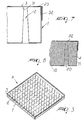
- Figure 1 is a plan view of the shape, spread out flat, of a square of sheet metal to be subsequently shaped, which constitutes the box-like element, on the surface of which wings to be folded are pre-cut, such wings being all orientated in the same direction;
- Figure 2 is a plan view of a second possible shape, spread out flat, of a square of sheet metal to be subsequently shaped, on the surface of which wings to be folded are pre-cut, such wings being divided into four quarters of the area, the wings of each area being orientated in a different direction;
- Figure 3 is an perspective view of the plymetal panel assembly, illustrating the internal structural part of the box-like element
- Figure 4 is a plan view of the plymetal panel of Figure 3;
- Figure 5 is a side view of the plymetal panel of Figure 3;
- Figure 6 is a sectional view of the plymetal panel of Figure 4, taken along the line A-A;
- Figure 7 is a sectional view of the plymetal panel without the insulating filler material, taken at the border and affected by the cover, detail B;
- Figure 8 is another view of the detail of Figure 7, illustrating the use of filler material.
- a plymetal panel A particularly for forming floating or conventional floors, but also for vertical applications, is composed of a box-like structure 1 formed by pressing and folding a metal sheet, for example 1a, 1b.
- Such box-like structure is composed of a base 10, which in the specific case has a square plan shape and has, along its perimeter, a corresponding lip 11 which is continuous or discontinuous and forms a border along the four sides.
- the lip 11, instead of being perpendicular to the base 10, is inclined slightly outward, so as to give the box-like structure 1 a certain perimetric taper.
- a plurality of wings 2 are cut at the base 10 of the box-like structure 1, so that at least one side thereof 20 remains connected and acts as a hinge.
- the wings By flexing and bending permanently the wings 2 toward the inside of the box-like structure 1, for example in a condition that is perpendicular to the base 10, the wings, like spikes, are arranged so that the end 21, 22 lies in contact with the lower side 31 of the upper cladding layer or of the cover 3 coupled to the box-like structure 1.
- the shape of the resting ends 21, 22 can vary according to requirements.
- the end 21 of the wings is pointed and is produced by the convergence of the two inclined top sides.
- the end 22 is square and flat in order to increase the contact surface.
- the sides of the folded wings 2 can be inclined, thus giving a certain taper to the wings 2 as shown in the figures or alternatively, as in Figures 1 and 2, they can be parallel.
- a layer of insulating filler material 4 is further provided inside the box-like structure 1 and at least partially includes the wings 2.
- such material 4 can be constituted by a panel that is cut to size and made of expanded or extruded polystyrene, preferably of the fire-resistant type.
- the material 4 can consist of expanded polyurethane or, as an alternative, rock wool or glass or wood wool.
- the box-like structure 1, with the corresponding insulating filler material 4, is closed by a cover 3.
- the cover 3 is constituted by a sheet of metal that is worked along its edges 32 and folded inward together with a corresponding portion of the lip 11, seaming the entire component perimetrically.
- the metal sheet 3 can be rough or finished at the outer surface 33, and in the latter case the relevant finishing treatments are applied, such as galvanization, coating, and others, or can be coupled to other more valuable cladding materials, such as for example linoleum.
- the metal cover 3 it is possible to connect a cover composed of a wood panel that is uniform or has another configuration, for example in slats or of the parquet type.
- wings 2 Another characteristic, which is susceptible of variations, is the arrangement of the wings 2.
- wings 2 having the same orientation are cut into the metal sheet 1a at the base surface 10.
- the base surface 10 is instead divided into four sectors, with wings 2 that have diametrically opposite orientations in pairs.
- the wings 2, once folded may also not be arranged at right angles to the base 10, but can be given a certain inclination. This is the case of a vertical application of the plymetal panel A, in which the wings 2 are orientated upward in order to facilitate the support and stabilization of the filler material 4.
- box-like structure 1 can consist of a staggered distribution of the wings 2, so as to allow to provide, at the base 10, reinforcement ribs, two in the specific case, which by mutually intersecting at the center run along the diagonals of the box-like element 1 and therefore of the plymetal panel A.
- reinforcement ribs two in the specific case, which by mutually intersecting at the center run along the diagonals of the box-like element 1 and therefore of the plymetal panel A.
- a welding spot in a logical point will render the entire assembly compact.
- part of the plymetal panel A can be subjected to more stress than other parts.
- at least the lower layer 1, and in the specific case the filler material 4 and the cover 3, are affected by a hole that can be closed externally by a plug. By removing the plug and inserting through the hole a foot that can be adjusted by means of a screw, it is possible to rest a central support on the floor, giving the plymetal panel A an unusual strength.
Landscapes
- Engineering & Computer Science (AREA)
- Architecture (AREA)
- Civil Engineering (AREA)
- Structural Engineering (AREA)
- Physics & Mathematics (AREA)
- Thermal Sciences (AREA)
- General Engineering & Computer Science (AREA)
- Floor Finish (AREA)
- Building Environments (AREA)
Applications Claiming Priority (2)
| Application Number | Priority Date | Filing Date | Title |
|---|---|---|---|
| IT2001TV000090A ITTV20010090A1 (it) | 2001-07-06 | 2001-07-06 | Pannello con struttura autoportante per pavimentazione e pareti |
| ITTV20010090 | 2001-07-06 |
Publications (2)
| Publication Number | Publication Date |
|---|---|
| EP1273730A2 true EP1273730A2 (de) | 2003-01-08 |
| EP1273730A3 EP1273730A3 (de) | 2003-08-06 |
Family
ID=11460097
Family Applications (1)
| Application Number | Title | Priority Date | Filing Date |
|---|---|---|---|
| EP02014043A Withdrawn EP1273730A3 (de) | 2001-07-06 | 2002-06-28 | Bauplatte mit selbsttragender Struktur für Böden und Wände |
Country Status (2)
| Country | Link |
|---|---|
| EP (1) | EP1273730A3 (de) |
| IT (1) | ITTV20010090A1 (de) |
Cited By (2)
| Publication number | Priority date | Publication date | Assignee | Title |
|---|---|---|---|---|
| US8769901B2 (en) | 2010-05-28 | 2014-07-08 | The Diller Corporation | Cladding system for building laminates |
| EP4367338A1 (de) * | 2021-07-08 | 2024-05-15 | Saint-Gobain Isover | Vorgefertigtes isolierpaneel |
Families Citing this family (1)
| Publication number | Priority date | Publication date | Assignee | Title |
|---|---|---|---|---|
| CN110230379B (zh) * | 2019-07-23 | 2023-10-03 | 佛山市东鹏陶瓷有限公司 | 一种隔音良好的瓷砖铺贴装置及其铺贴方法 |
Citations (6)
| Publication number | Priority date | Publication date | Assignee | Title |
|---|---|---|---|---|
| GB2057529A (en) | 1979-09-21 | 1981-04-01 | Vale D | Building panels and building constructions |
| GB2156874A (en) | 1984-04-06 | 1985-10-16 | Redpath Dorman Long Ltd | Dry-laid floors |
| DE3937969A1 (de) | 1989-11-15 | 1991-05-16 | Peter Schmitz | Bodenplatte mit integrierten quertraegern |
| DE4239884A1 (de) | 1992-11-27 | 1994-06-01 | Rainer Baars | Tafelförmiges Wand- und/oder Bodenelement |
| US5661937A (en) | 1995-04-17 | 1997-09-02 | Johnson-Doppler Lumber | Mezzanine floor panel |
| FR2765906A1 (fr) | 1997-07-09 | 1999-01-15 | Pab Services | Element modulaire leger pour plancher, notamment de batiment |
Family Cites Families (6)
| Publication number | Priority date | Publication date | Assignee | Title |
|---|---|---|---|---|
| US2089326A (en) * | 1931-08-24 | 1937-08-10 | Mccord Radiator & Mfg Co | Sheet metal prong forming apparatus |
| CH287302A (de) * | 1951-01-24 | 1952-11-30 | Meteoor Nv Betonfabriek | Vorrichtung zum Ausschneiden und rechtwinkligen Herausbiegen von an ihrem freien Ende verbreiterten Zungen aus einer flachen Metallplatte. |
| DE2734775A1 (de) * | 1976-08-05 | 1978-02-09 | Idemitsu Kosan Co | Konstruktionsmaterial |
| NL8802915A (nl) * | 1988-09-29 | 1990-07-02 | Hunter Douglas Ind Bv | Demontabele wand- of plafondkonstruktie, vrijdragend rechthoekig paneel voor een wand- of plafondbekleding en werkwijze voor het vervaardigen daarvan. |
| AT739U2 (de) * | 1995-10-18 | 1996-04-25 | Adolf Jun Jandl | Plattenförmiges bauelement |
| DE19822405C1 (de) * | 1998-05-19 | 2000-01-13 | Baunach Klaus Peter | Hohlraumbodenkonstruktion |
-
2001
- 2001-07-06 IT IT2001TV000090A patent/ITTV20010090A1/it unknown
-
2002
- 2002-06-28 EP EP02014043A patent/EP1273730A3/de not_active Withdrawn
Patent Citations (6)
| Publication number | Priority date | Publication date | Assignee | Title |
|---|---|---|---|---|
| GB2057529A (en) | 1979-09-21 | 1981-04-01 | Vale D | Building panels and building constructions |
| GB2156874A (en) | 1984-04-06 | 1985-10-16 | Redpath Dorman Long Ltd | Dry-laid floors |
| DE3937969A1 (de) | 1989-11-15 | 1991-05-16 | Peter Schmitz | Bodenplatte mit integrierten quertraegern |
| DE4239884A1 (de) | 1992-11-27 | 1994-06-01 | Rainer Baars | Tafelförmiges Wand- und/oder Bodenelement |
| US5661937A (en) | 1995-04-17 | 1997-09-02 | Johnson-Doppler Lumber | Mezzanine floor panel |
| FR2765906A1 (fr) | 1997-07-09 | 1999-01-15 | Pab Services | Element modulaire leger pour plancher, notamment de batiment |
Cited By (4)
| Publication number | Priority date | Publication date | Assignee | Title |
|---|---|---|---|---|
| US8769901B2 (en) | 2010-05-28 | 2014-07-08 | The Diller Corporation | Cladding system for building laminates |
| US8991127B2 (en) | 2010-05-28 | 2015-03-31 | The Diller Corporation | Cladding system for building laminates |
| EP4367338A1 (de) * | 2021-07-08 | 2024-05-15 | Saint-Gobain Isover | Vorgefertigtes isolierpaneel |
| EP4367338B1 (de) * | 2021-07-08 | 2026-02-25 | Saint-Gobain Isover | Vorgefertigtes isolierpaneel |
Also Published As
| Publication number | Publication date |
|---|---|
| EP1273730A3 (de) | 2003-08-06 |
| ITTV20010090A1 (it) | 2003-01-06 |
Similar Documents
| Publication | Publication Date | Title |
|---|---|---|
| US7328667B1 (en) | Three dimensional plated deck | |
| US6711872B2 (en) | Lightweight panel construction | |
| US5259157A (en) | Acoustical deck panel assembly | |
| US5172527A (en) | Acoustical deck panel assembly | |
| US5598677A (en) | Insulated covering for building sheathing | |
| US4517782A (en) | Construction element | |
| US6584742B1 (en) | Oriented strand board wall panel system | |
| US5540023A (en) | Lathing | |
| US5740644A (en) | Wall with horizontal metal stud and reinforcement channel therefor | |
| WO2000030845A1 (en) | Multilayer panel and use thereof as a formwork | |
| US20030233796A1 (en) | Roof panel for a sun room | |
| US4572857A (en) | Insulating board of composite material | |
| EP0450731A1 (de) | Panelartiges Isolierelement für Dächer oder Aussenwände | |
| US20080053031A1 (en) | Assembling and Arrangement Flat Element Consisting of One or Several Elements | |
| US20050247024A1 (en) | Modular building structure | |
| JP5837921B2 (ja) | 床を支持するための部分構造及び該部分構造を備える床システム | |
| JPH06158831A (ja) | 遮音性床板 | |
| EP1247641A1 (de) | Boden- oder Wandplatten aus synthetischem Material und deren Herstellung | |
| JP4214289B2 (ja) | 壁構築方法 | |
| US20050109127A1 (en) | Structural beam member | |
| ITTV20010090A1 (it) | Pannello con struttura autoportante per pavimentazione e pareti | |
| US20060037269A1 (en) | Stiffness reinforced floor panel for a raised floor system | |
| JP7726260B2 (ja) | 床材および建築物 | |
| DE9310221U1 (de) | Dämmkörper | |
| GB2306182A (en) | Acoustic material and method of use |
Legal Events
| Date | Code | Title | Description |
|---|---|---|---|
| PUAI | Public reference made under article 153(3) epc to a published international application that has entered the european phase |
Free format text: ORIGINAL CODE: 0009012 |
|
| AK | Designated contracting states |
Kind code of ref document: A2 Designated state(s): AT BE CH CY DE DK ES FI FR GB GR IE IT LI LU MC NL PT SE TR |
|
| AX | Request for extension of the european patent |
Free format text: AL;LT;LV;MK;RO;SI |
|
| PUAL | Search report despatched |
Free format text: ORIGINAL CODE: 0009013 |
|
| AK | Designated contracting states |
Designated state(s): AT BE CH CY DE DK ES FI FR GB GR IE IT LI LU MC NL PT SE TR |
|
| AX | Request for extension of the european patent |
Extension state: AL LT LV MK RO SI |
|
| RIC1 | Information provided on ipc code assigned before grant |
Ipc: 7B 32B 3/24 B Ipc: 7B 21D 28/10 B Ipc: 7E 04F 15/024 B Ipc: 7E 04F 13/08 B Ipc: 7E 04C 2/34 B Ipc: 7E 04C 2/292 A |
|
| STAA | Information on the status of an ep patent application or granted ep patent |
Free format text: STATUS: THE APPLICATION HAS BEEN WITHDRAWN |
|
| 18W | Application withdrawn |
Effective date: 20040206 |