EP1273739A2 - Vorrichtung und Verfahren zum Manipulieren von Lasten, insbesondere von Stahlmatten aus Stahlstäben - Google Patents
Vorrichtung und Verfahren zum Manipulieren von Lasten, insbesondere von Stahlmatten aus Stahlstäben Download PDFInfo
- Publication number
- EP1273739A2 EP1273739A2 EP02010809A EP02010809A EP1273739A2 EP 1273739 A2 EP1273739 A2 EP 1273739A2 EP 02010809 A EP02010809 A EP 02010809A EP 02010809 A EP02010809 A EP 02010809A EP 1273739 A2 EP1273739 A2 EP 1273739A2
- Authority
- EP
- European Patent Office
- Prior art keywords
- blade
- webbing
- carrier
- securing element
- loop
- Prior art date
- Legal status (The legal status is an assumption and is not a legal conclusion. Google has not performed a legal analysis and makes no representation as to the accuracy of the status listed.)
- Granted
Links
Images




Classifications
-
- B—PERFORMING OPERATIONS; TRANSPORTING
- B65—CONVEYING; PACKING; STORING; HANDLING THIN OR FILAMENTARY MATERIAL
- B65D—CONTAINERS FOR STORAGE OR TRANSPORT OF ARTICLES OR MATERIALS, e.g. BAGS, BARRELS, BOTTLES, BOXES, CANS, CARTONS, CRATES, DRUMS, JARS, TANKS, HOPPERS, FORWARDING CONTAINERS; ACCESSORIES, CLOSURES, OR FITTINGS THEREFOR; PACKAGING ELEMENTS; PACKAGES
- B65D63/00—Flexible elongated elements, e.g. straps, for bundling or supporting articles
- B65D63/18—Elements provided with handles or other suspension means
-
- B—PERFORMING OPERATIONS; TRANSPORTING
- B66—HOISTING; LIFTING; HAULING
- B66C—CRANES; LOAD-ENGAGING ELEMENTS OR DEVICES FOR CRANES, CAPSTANS, WINCHES, OR TACKLES
- B66C1/00—Load-engaging elements or devices attached to lifting or lowering gear of cranes or adapted for connection therewith for transmitting lifting forces to articles or groups of articles
- B66C1/10—Load-engaging elements or devices attached to lifting or lowering gear of cranes or adapted for connection therewith for transmitting lifting forces to articles or groups of articles by mechanical means
- B66C1/12—Slings comprising chains, wires, ropes, or bands; Nets
- B66C1/18—Band-type slings
-
- E—FIXED CONSTRUCTIONS
- E04—BUILDING
- E04C—STRUCTURAL ELEMENTS; BUILDING MATERIALS
- E04C5/00—Reinforcing elements, e.g. for concrete; Auxiliary elements therefor
- E04C5/01—Reinforcing elements of metal, e.g. with non-structural coatings
- E04C5/02—Reinforcing elements of metal, e.g. with non-structural coatings of low bending resistance, i.e. of essentially one-dimensional [1D] or two-dimensional [2D] extent
- E04C5/04—Mats
-
- E—FIXED CONSTRUCTIONS
- E04—BUILDING
- E04G—SCAFFOLDING; FORMS; SHUTTERING; BUILDING IMPLEMENTS OR AIDS, OR THEIR USE; HANDLING BUILDING MATERIALS ON THE SITE; REPAIRING, BREAKING-UP OR OTHER WORK ON EXISTING BUILDINGS
- E04G21/00—Preparing, conveying, or working-up building materials or building elements in situ; Other devices or measures for constructional work
- E04G21/14—Conveying or assembling building elements
- E04G21/16—Tools or apparatus
- E04G21/169—Tools or apparatus specially adapted for working-up reinforcement mats
Definitions
- the invention relates to a device for manipulation loads, in particular steel mats made of steel bars or similar mats.
- the invention has for its object a device for manipulating loads, especially steel mats or create similar mats that are simple and functionally fitting way and also the legal safety regulations are sufficient.
- a suitable method for manipulating loads can be specified.
- a device for manipulating loads in particular steel mats made of steel bars, with a belt strap which has a loop at least at its first end, the belt strap being able to be guided around one or more steel bars of the steel mats and with its second end being able to be passed through the loop of the first end to form a loop comprising the load or the steel bars and with a securing element which can be fastened to the belt strap outside the loop and has an outer circumference which is larger by a predetermined amount than the inner circumference of the loop of the first end, the securing element only by destroying the belt strap and / or the securing element from the belt strap is removable.
- the securing element is fastened to the belt webbing by means of a blade or similar penetration means which reaches through the belt webbing.
- This measure first of all enables simple assembly. This is because the conventional webbing with at least one loop at one end is simply placed around the steel rods and then the other end of the webbing is pulled through the loop, forming a loop, so that a firm connection between the individual steel mats is achieved.
- the safety element according to the invention prevents the removal of this loop from the steel mats. Because the securing element is dimensioned or with its outer circumference so matched to the inner circumference of the loop that the free end of the belt can no longer be pulled through the loop at the other end of the belt. It blocks the loop and keeps it closed.
- the securing element can only be removed from the webbing by destroying the webbing and / or the securing element from the webbing. This is because the securing element is fastened to the webbing by means of a blade or similar penetrating means which reaches through the webbing. If, for example, the securing element is forcibly removed from the webbing or the webbing is pulled out of the securing element, the blade or the penetrating means cuts through partial areas of the webbing, so that reuse is impossible. The same naturally applies if the webbing is cut to remove it from the steel mats.
- the blade can be a metal blade, act in particular steel blade. But it also comes other means of enforcement, such as B. a sharp-edged Metal plate, a sword or for example a Rod, pin or wedge that passes through the webbing.
- the securing element has a guide slot, through which the second end of the webbing for attachment the securing element is guided. It is Securing element on the webbing by means of the webbing blade penetrating in the area of the guide slot fixed.
- the Blade the webbing approximately orthogonal to the webbing surface and approximately parallel to the longitudinal direction of the webbing. On This ensures that the blade is on the one hand in a relatively simple manner in the webbing introduced or inserted through the webbing can. On the other hand is more reliable at the same time Attachment of the securing element to the webbing ensures that the webbing is removed by force is actually damaged.
- this Fuse element a fuse block with a guide chamber with the guide slot for the webbing on, on which or in which a blade carrier carrying the blade attachable or usable and orthogonal to the Belt strap slidable and in a predetermined position can be locked to the webbing in the securing block. Consequently, the securing element consists of the one hand Fuse block and on the other hand from the blade carrier, which to fix the fuse element in the fuse block can be used or placed on this. in the In the course of inserting or putting on the blade carrier then reaches through the blade attached to the blade carrier Webbing. Overall, this makes assembly very easy of the securing element with at the same time flawless Function and high stability achieved.
- the blade carrier is preferably about a pivot axis pivoted on the fuse block or he can be arranged accordingly on the fuse block. Fixing the securing element on the webbing consequently takes place in the fuse block inserted blade carrier pivoted about the pivot axis the blade through the guide slot passes through the webbing.
- the blade carrier is preferably on has one end of a bearing recess, which on a corresponding one that forms the pivot axis Bearing pin or pin or on bearing pin sections is attachable or attachable.
- the bearing recess can formed, for example, as it were an open groove be inserted at the end into the blade carrier is.
- This embodiment is characterized by special easy assembly because the blade carrier can be without further ado on the fuse block and then swivel in this.
- this embodiment may be useful if the Fuse block on the inside an arcuate guide surface for the blade carrier, which is the End of the blade carrier facing away from the bearing recess in the train of fixing, if necessary, with a predetermined distance to the Guide surface slides along or along this to be led. In this way, the trajectory of the Blade holder fixed within the fuse block predetermined and prevents the blade holder from using its bearing recess from the bearing pin or pin slip. Overall, assembly is simple significantly improved.
- the guide chamber facing away from the blade carrier Wall a recess for receiving through the Guide slot and the webbing gripping tip of the Has a blade.
- This recess is preferably in Insertion direction of the blade tapering recess or Recording trained.
- the fuse block can attach itself to the guide chamber subsequent carrier receiving chamber for the blade carrier exhibit.
- the Fuse block on the one hand from the guide chamber, through which the webbing is passed through and on the other hand from the carrier receiving chamber into which the blade carrier then inserted or on which of the blade carriers is plugged on.
- Carrier receiving chamber and guide chamber - and thus the fuse block - can be made in one piece, e.g. B. be made of plastic and are through a wall separated from each other, which is an opening for the in the guide chamber has a blade to be inserted. It is this opening then preferably as in Insertion direction of the blade tapering gap is formed.
- the management chamber is on the one hand and Carrier receiving chamber, on the other hand, in this preferred Embodiment as a common guide chamber or Guide and carrier receiving chamber trained. This is both in manufacturing technology and in assembly technology Respectful.
- the blade carrier can have a blade recess, in which the blade is insertable and in which the blade is then attachable.
- the blade carrier is therefore considered separate component z. B. made of plastic.
- the blade which for example is made of metal in the blade recess insert, with the attachment of the blade in the Blade recess z. B. positive, frictional and / or can be done adhesively.
- a detachable connection e.g. B. a connector be provided so that the blade is in the blade carrier can be replaced easily.
- the blade support as two or multi-part blade carrier with at least two blade carrier halves is trained. These blade support halves are fixing the blade between the blade support halves connectable, preferably plugged together. At least one of the blade support halves can be used at least one connecting pin and the other blade carrier half at least one corresponding one Have connection receptacle in which the connecting pin preferably with the formation of a clamp and / or Interlocking connection engages. In the course of assembly, consequently the two blade support halves in a simple manner stick together and in this context the blade in Fasten the specified position.
- a special one reliable attachment of the blade between the Blade support halves is guaranteed when the blade at least one opening, recess or - has formation, which of the connecting pin in In the process of assembling the blade support halves is penetrated. In this way one becomes as it were non-positive and positive attachment of the blade between the blade support halves guaranteed.
- an adhesive bond between the two Blade carrier halves and / or the blade between the Blade support halves can be provided.
- Blade carrier in or on the guide chamber or Carrier receiving chamber can be snapped in or snapped on.
- This can the blade carrier on the outside or at least on the outside two z. B. opposite locking legs and / or Have locking lugs, which in corresponding locking recesses in or on the carrier receiving chamber or in or grab the guide chamber.
- the snap connection prevents the securing element from moving easily Way can be removed from the webbing.
- each locking leg or each tab of the blade holder has at least two in Insert the blade holder one after the other Arranged recesses arranged, which a Advance and form a main stop.
- the webbing can be passed through the guide slot in advance, while the blade the webbing in the brunt be upheld.
- the First bring the blade carrier into the pre-locking position, in which the locking legs in the first two Grip recesses.
- the guide slot is removed from the blade in the pre-assembly position still released, leaving the webbing in the guide slot can still be moved freely or by this can be passed through.
- the carrier receiving chamber and possibly also the guide chamber as well as the blade holder can be rectangular or have a square base. It is also possible that the carrier receiving chamber and possibly the Guide chamber and the blade carrier a round, z. B. have a circular base. According to a preferred embodiment the fuse element is essentially made of Made of plastic.
- the Safety block which consists of the guide chamber and possibly the carrier receiving chamber and on the other hand the Blade carriers are plastic components. With the blade itself or the enforcement agent preferably around a metal component, for example a Steel blade, which in the manner described on Blade holder is attached.
- the invention also relates to that described Securing element for the device described. That is, the securing element is also protected independently posed.
- the invention further relates to a method for manipulation of steel mats made of steel bars according to the patent claims 17 and 18.
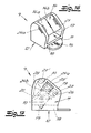
- the device for manipulating Steel mats 1 shown from steel bars 2.
- the device consists of a webbing 3, which at its first end 4 and at its second end 5 each has a loop 6, 7, the belt strap 3 can be guided around one or more steel rods 2 of the steel mat 1 is and with its second end 5 to form a die Steel rods 2 comprising loop 8 through the loop 6 of the first end 4 can be passed.
- the Device a securing element 9, which outside the sling 8 is attached to the webbing 3 and which has an outer circumference that is a predetermined amount larger than the inner circumference of the loop 6 of the first end 4 is.
- Fig. 1 shows the Device according to the invention, consisting of webbing 3 and Securing element 9, in the assembled state, d. H. the webbing 3 was first around the two steel bars 2 around and then the second end 5 of the webbing 3 through the loop 6 at the first end 4 of Belt strap 3 passed so that the loop 8th forms around the two steel rods 2. Then that became Securing element 9 outside the loop 8 on the webbing 3 attached, the securing element 9 on the one hand and the loop 6 at the first end 4 of the webbing 3 on the other hand, are coordinated so that the Loop 6 is not pulled off the securing element 9 can be.
- the securing element 9 only through Destruction of the webbing 3 and / or the securing element 9 can be removed from the webbing 3.
- the securing element 9 is the second end 5 of the webbing 3 by one Guide slot 11 of the securing element 9, wherein the securing element 9 on the webbing 3 by means of the Belt strap 3 penetrating in the area of the guide slot 11 Blade 10 is fixed.
- the Blade 10 of the webbing 3 approximately orthogonal to the webbing surface and approximately parallel to the longitudinal direction of the webbing.
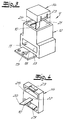
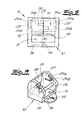
- Fig. 3 shows a first embodiment of the Securing element 9 in the unmounted state.
- the securing element 9 on the one hand a fuse block 12 with a guide chamber 13 which is the guide slot 11 for the webbing 3rd having.
- the securing element 9 consists of a blade support 14 which carries the blade 10 and in the fuse block 12 can be used.
- the Blade carrier 14 orthogonal to the in the course of insertion Webbing 3 slidable and in a predetermined Position of the webbing 3 in the securing block 12 lockable.
- the securing element 9 To assemble the securing element 9 first the second end 5 of the webbing 3 in the through the arrow 15 serving as an assembly instruction on Fuse block 12 marked by the direction Guide slot 11 and thus through the guide chamber 13th and the fuse block 12 passed. Subsequently is the blade carrier 14 with the blade 10 from the in Fig. 3 position shown inserted into the fuse block 12 and fastened in this. Then the Blade 10 of the webbing 3 so that the entire securing element 9 is fixed to the webbing 3. same for for the embodiment according to FIGS. 13 and 14.
- the blade 10 8 are the blade carrier and the Blade 10 on the one hand and the webbing 3 on the other hand in assembled state indicated by dash-dotted lines.
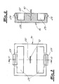
- the Recess 19 on the inside of the bottom 18 of the Fuse block 12 is as in the insertion direction Blade 10 tapered recess 19 formed. Also this can be seen in particular in FIG. 8.
- the Fuse block 12 adjoining the guide chamber 13 Carrier receiving chamber 21 for the blade carrier 14. This means that the guide chamber 13 and the Carrier receiving chamber 21 together the fuse block 12th 7 to 9 form. Between the lead chamber 13 and the carrier receiving chamber 21 is a wall 16 with an opening 17 for the in the guide chamber 13th Blade 10 to be inserted. This opening 17 is tapered in the direction of insertion of the blade 10 Gap 17 formed.
- Carrier receiving chamber and guide chamber are one single guide chamber 13 or guide and carrier receiving chamber 13 summarized. This also applies to the Embodiment according to FIG. 16.
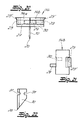
- the blade carrier 14 For fastening the blade 10 in the blade carrier 14 points the blade carrier 14 has a blade recess 22 (cf. 4 to 6 in particular). In this blade recess 22nd the blade 10 is inserted so that the blade 10 in the blade recess 22 and thus on the blade carrier 14 is attached.
- the connection of the blade carrier 14 to the carrier receiving chamber 21 and consequently with the fuse block 12 takes place via a snap-in connection.
- the blade holder points to this 14 circumferentially two opposing locking legs 23 on, which with locking lugs in corresponding Grip recesses 24 in the carrier receiving chamber 21. 3 to 6 are two in the blade carrier 14 Mounting pockets 25 or recesses molded into which the locking leg 23 in the course of snapping into Carrier receiving chamber 21 can avoid. Between these Assembly pockets 25 is the blade 10 in the Blade recess 22 attached.
- FIGS. 13 to 15 are in the guide chamber 13 or in the common Carrier receiving and guide chamber 13 also on both sides
- Two latching recesses 24a, 24b are provided, respectively in the insertion direction of the blade carrier 14 one after the other or behind each other.
- the locking recesses 24a and 24b with predetermined distance are arranged one below the other.
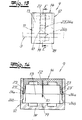
- the blade carrier 14 with its Locking legs 23 in the upper locking recesses 24a and thus in a pre-locking position or pre-assembly position. In In this position, the webbing 3 can still be moved through the Guide slot 11 through or free in this move.
- the blade carrier 14 closes with his Surface flush with the upper edges of the fuse block 12 from.
- the blade carrier 14 is further in the Fuse block 12 pressed in so that the locking lugs 23 'on the locking legs 23 again from the locking recesses Remove 24a and finally into the recesses 24b grab and reach the main rest.
- Fig. 15 shown position passes through the blade 10 the webbing 3.
- the blade carrier 14 is located in one sunk into the security block 12, as it were Position so that it is not easily removed again can be. This ensures that the Safety block 12 not without damage to the webbing 3 can be removed.
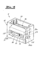
- the securing element 9 has also a fuse block 12 with a guide chamber 13 with the guide slot 11 for the webbing 3.
- the blade 10 load-bearing blade carrier 14 can be used.
- the blade carrier 14 is one Pivot axis 26 can be pivoted on the securing block 12 arranged.
- the blade carrier 14 has at one end a bearing recess 27 in the form of an end, in Cross-section U-shaped groove 27, which on a corresponding, forming the pivot axis 26 Bearing pin or bearing pin 26 attachable or attachable is.
- a bearing recess 27 in the form of an end, in Cross-section U-shaped groove 27, which on a corresponding, forming the pivot axis 26 Bearing pin or bearing pin 26 attachable or attachable is.
- the securing element 9 to the webbing 3 can now be placed on the bearing pin 26 Swing blade carrier 14 about the pivot axis (cf. Fig. 17).
- the blade holder is attached to his Bearing recess 27 facing away from the end in the Safety block pressed in and swiveled.
- FIGS. 16 to 22 show that also in this embodiment the blade carrier on the outside two opposing locking lugs 23 ' has, which in corresponding locking recesses 24a, 24b engage in the guide chamber 13.
- the Side walls of the guide chamber 13 inside for each Latch 23 'of the blade carrier 14 two in the direction of insertion of the blade support 14 arranged one after the other Locking recesses 24a, 24b are provided, which also have a Advance and form a main stop.
- the blade carrier 14 as a two-part blade carrier two blade support halves 14 a, 14 b formed.
- This Blade support halves 14a, 14b are under fixation of the Blade 10 between the blade support halves 14a, 14b can be plugged together (see in particular Fig. 20).
- Everybody points out the blade support halves 14a, 14b each have one Connection pin 29 on.
- each of the Blade support halves 14a, 14b one with the connecting pin 29 corresponding to the other half of the blade support Connection receptacle 30 in which the connecting pin 29 to form a clamp and / or snap connection intervenes.
- the blade 10 has two corresponding mounting openings or mounting shapes 31 on which of the connecting pins 29 in In the course of assembling the blade support halves 14a, 14b be penetrated so that a perfect fixation the blade 10 between the blade support halves 14a, 14b is guaranteed.
- FIGS. 1 to 9 and 13 to 15 is that of the guide chamber 13 and possibly the carrier receiving chamber 21 existing fuse block 12 essentially cuboid with a rectangular base educated.
- 10 to 12 show a modified Embodiment of a blade support 14, which a has a circular base.
- This circular Blade carrier 14 can either be in a fuse block 12 7 to 9 are used. But there is also the ability to match the shape of the blade carrier adapted guide block with a round base use. Such is not in the figures shown.
- the securing element 9 is essentially made of plastic. That means it is in the fuse block 12 and the blade carrier 14 or the blade support halves 14a, 14b each in one piece trained plastic components.
- the one in the Blade carrier 14 inserted blade 10 is, however, as Sheet steel blade formed.
Landscapes
- Engineering & Computer Science (AREA)
- Architecture (AREA)
- Mechanical Engineering (AREA)
- Civil Engineering (AREA)
- Structural Engineering (AREA)
- Automotive Seat Belt Assembly (AREA)
- Emergency Lowering Means (AREA)
- Looms (AREA)
- Gates (AREA)
- Toys (AREA)
- Investigating Or Analysing Materials By Optical Means (AREA)
- Load-Engaging Elements For Cranes (AREA)
- Basic Packing Technique (AREA)
Abstract
Description
mit einem Gurtband, das zumindest an seinem ersten Ende eine Schlaufe aufweist, wobei das Gurtband um ein oder mehrere Stahlstäbe der Stahlmatten führbar ist und mit seinem zweiten Ende unter Bildung einer die Last bzw. die Stahlstäbe umfassenden Schlinge durch die Schlaufe des ersten Endes hindurchführbar ist
und mit einem Sicherungselement, welches außerhalb der Schlinge an dem Gurtband befestigbar ist und einen Außenumfang aufweist, welcher um ein vorgegebenes Maß größer ist als der Innenumfang der Schlaufe des ersten Endes, wobei das Sicherungselement nur durch Zerstörung des Gurtbandes und/oder des Sicherungselementes vom Gurtband entfernbar ist. Dabei ist das Sicherungselement erfindungsgemäß an dem Gurtband mittels einer das Gurtband durchgreifenden Klinge oder dergleichen Durchgreifmittel befestigt. - Durch diese Maßnahme wird zunächst einmal eine einfache Montage ermöglicht. Denn das herkömmliche Gurtband mit zumindest einer Schlaufe an seinem einen Ende wird einfach um die Stahlstäbe gelegt und anschließend wird das andere Ende des Gurtbandes unter Schlingenbildung durch die Schlaufe gezogen, so dass eine feste Verbindung zwischen den einzelnen Stahlmatten verwirklicht wird. Das Entfernen dieser Schlinge von den Stahlmatten wird durch das erfindungsgemäße Sicherungselement verhindert. Denn das Sicherungselement ist so dimensioniert bzw. mit seinem Außenumfang so auf den Innenumfang der Schlaufe abgestimmt, dass sich das freie Ende des Gurtbandes nicht mehr durch die Schlaufe am anderen Ende des Gurtbandes hindurchziehen lässt. Es blockiert gleichsam die Schlinge und hält diese geschlossen. Dabei lässt sich das Sicherungselement von dem Gurtband nur durch Zerstörung des Gurtbandes und/oder des Sicherungselementes vom Gurtband entfernen. Denn die Befestigung des Sicherungselementes am Gurtband erfolgt mittels einer das Gurtband durchgreifenden Klinge oder dergleichen Durchgreifmittel. Wird das Sicherungselement beispielsweise gewaltsam vom Gurtband entfernt bzw. das Gurtband aus dem Sicherungselement herausgezogen, so durchschneidet die Klinge bzw. das Durchgreifmittel Teilbereiche des Gurtbandes, so dass eine Wiederverwendung ausgeschlossen ist. Gleiches gilt selbstverständlich, wenn das Gurtband zerschnitten wird, um es von den Stahlmatten zu entfernen.
- Fig. 1
- eine erfindungsgemäße Vorrichtung zum Manipulieren von Stahlmatten aus Stahlstäben in montiertem Zustand,
- Fig.2
- den Gegenstand nach Fig. 1 ohne Stahlmatte,
- Fig. 3
- ein Sicherungselement für eine Vorrichtung gemäß Fig. 2 in perspektivischer Darstellung,
- Fig. 4
- den Klingenträger des Sicherungselementes gemäß Fig. 3 in einer anderen Ansicht,
- Fig. 5
- den Gegenstand nach Fig. 4 in einer anderen Ansicht,
- Fig. 6
- einen Schnitt in Richtung A-A durch den Gegenstand nach Fig. 5,
- Fig. 7
- den Sicherungsblock des Sicherungselementes gemäß Fig. 3 in einer Seitenansicht,
- Fig. 8
- einen Schnitt in Richtung B-B durch den Sicherungsblock gemäß Fig. 7,
- Fig. 9
- den Gegenstand nach Fig. 7 in einer Draufsicht,
- Fig. 10
- einen Klingenträger in abgewandelter Ausführungsform,
- Fig. 11
- einen Schnitt entlang der Linie C-C durch den Gegenstand nach Fig. 10 und
- Fig. 12
- einen Schnitt durch den Gegenstand nach Fig. 10 entlang der Linie D-D.
- Fig. 13
- eine andere Ausführungsform der Erfindung in einer Seitenansicht,
- Fig. 14
- einen Schnitt durch den Gegenstand nach Fig. 13 entlang der Linie E-E,
- Fig. 15
- den Gegenstand nach Fig. 13 in perspektivischer Ansicht in einer anderen Montagestellung,
- Fig. 16
- ein Sicherungselement in einer weiteren Ausführungsform der Erfindung in perspektivischer Ansicht,
- Fig. 17
- den Gegenstand nach Fig. 16 in einer Seitenansicht,
- Fig. 18
- den Gegenstand nach Fig. 16 in einer Draufsicht,
- Fig. 19
- den Gegenstand nach Fig. 16 ohne Klingenträger,
- Fig. 20
- den Klingenträger des Gegenstandes nach Fig. 16,
- Fig. 21
- eine Klingenträgerhälfte des Gegenstandes der Fig. 20 in einer Draufsicht und
- Fig. 22
- die Klinge des Klingenträgers gemäß Fig. 20.
Claims (25)
- Vorrichtung zum Manipulieren von Lasten, insbesondere von Stahlmatten (1) aus Stahlstäben (2),
mit einem Gurtband (3), das zumindest an seinem ersten Ende (4) eine Schlaufe (6) aufweist, wobei das Gurtband (3) um ein oder mehrere Stahlstäbe (2) der Stahlmatten (1) führbar ist und mit seinem zweiten Ende (5) unter Bildung einer die Last umfassenden oder durchfassenden Schlinge (8) durch die Schlaufe (6) des ersten Endes (4) hindurchführbar ist,
und mit einem Sicherungselement (9), welches außerhalb der Schlinge (8) an dem Gurtband (3) befestigbar ist und einen Außenumfang aufweist, welcher um ein vorgegebenes Maß größer als der Innenumfang der Schlaufe (6) des ersten Endes (4) ist, wobei das Sicherungselement (9) nur durch Zerstörung des Gurtbandes (3) und/oder des Sicherungselementes (9) vom Gurtband (3) entfernbar ist. - Vorrichtung nach Anspruch 1, wobei das Sicherungselement (9) an dem Gurtband (3) mittels einer das Gurtband (3) durchgreifenden Klinge (10) oder dergleichen Durchgreifmittel befestigt ist.
- Vorrichtung nach Anspruch 2, wobei das zweite Ende (5) des Gurtbandes (3) zur Befestigung des Sicherungselementes(9) durch einen Führungsschlitz (11) des Sicherungselementes (9) geführt ist und wobei das Sicherungselement (9) an dem Gurtband (3) mittels der das Gurtband (3) im Bereich des Führungsschlitzes (11) durchgreifenden Klinge (10) fixiert ist.
- Vorrichtung nach Anspruch 2 oder 3, wobei die Klinge (10) das Gurtband (3) in etwa orthogonal zur Gurtbandoberfläche und in etwa parallel zur Gurtbandlängsrichtung durchgreift.
- Vorrichtung nach Anspruch 3 oder 4, wobei das Sicherungselement (9) einen Sicherungsblock (12) mit einer Führungskammer (13) mit dem Führungsschlitz (11) für das Gurtband (3) aufweist, auf welchen oder in welchen ein die Klinge (10) tragender Klingenträger (14) aufsetzbar bzw. einsetzbar und orthogonal zu dem Gurtband (3) verschiebbar sowie in einer vorgegebenen Position zu dem Gurtband (3) in dem Sicherungsblock (12) arretierbar ist.
- Vorrichtung nach Anspruch 3 oder 4, wobei das Sicherungselement (9) einen Sicherungsblock (12) mit einer Führungskammer (13) mit dem Führungsschlitz (11) für das Gurtband (3) aufweist, auf welchen oder in welchen ein die Klinge (10) tragender Klingenträger (14) aufsetzbar bzw. einsetzbar oder eingesetzt ist und zum Fixieren relativ zu dem Gurtband (3) verschwenkbar sowie in einer vorgegebenen Position zu dem Gurtband (3) in dem Sicherungsblock (12) arretierbar ist.
- Vorrichtung nach Anspruch 6, wobei der Klingenträger (14) um eine Schwenkachse (26) schwenkbar an dem Sicherungsblock (9) angeordnet ist.
- Vorrichtung nach Anspruch 7, wobei der Klingenträger (14) vorzugsweise an seinem einen Ende zumindest eine Lagerausnehmung (27) aufweist, welche auf einen korrespondierenden, die Schwenkachse bildenden Lagerbolzen oder -stift (26) oder auf Lagerbolzenabschnitte aufsetzbar oder aufsteckbar ist.
- Vorrichtung nach einem der Ansprüche 6 bis 8, wobei der Sicherungsblock (12) innenseitig eine bogenförmige Führungsfläche (28) für den Klingenträger (14) aufweist und wobei das der Lagerausnehmung (27) abgewandte Ende des Klingenträgers (14) im Zuge des Fixierens ggf. mit vorgegebenen Abstand an der Führungsfläche (28) entlang führbar ist.
- Vorrichtung nach einem der Ansprüche 5 bis 9, wobei die Führungskammer (13) in ihrer dem Klingenträger (14) abgewandten Wand (18) eine Ausnehmung (19) zur Aufnahme für die durch den Führungsschlitz (11) und das Gurtband (3) greifende Spitze (20) der Klinge (10) aufweist.
- Vorrichtung nach Anspruch 10, wobei die Ausnehmung (19) als sich in Einschubrichtung der Klinge (10) verjüngende Ausnehmung (19) ausgebildet ist.
- Vorrichtung nach einem der Ansprüche 5 bis 11, wobei der Sicherungsblock (12) eine sich an die Führungskammer (13) anschließende Trägeraufnahmekammer (21) für den Klingenträger (14) aufweist.
- Vorrichtung nach einem der Ansprüche 5 bis 12, wobei der Klingenträger (14) eine Klingenausnehmung (22) aufweist, in welche die Klinge (10) einsteckbar und zu befestigen ist.
- Vorrichtung nach einem der Ansprüche 5 bis 13, wobei der Klingenträger (14) als zwei- oder mehrteiliger Klingenträger mit zumindest zwei Klingenträgerhälften (14a, 14b) ausgebildet ist, welche unter Fixierung der Klinge (10) zwischen den Klingenträgerhälften miteinander verbindbar, vorzugsweise zusammensteckbar sind.
- Vorrichtung nach Anspruch 14, wobei zumindest die eine Klingenträgerhälfte (14a, 14b) zumindest einen Verbindungsstift (29) und die andere Klingenträgerhälfte (14a, 14b) zumindest eine korrespondierende Verbindungsaufnahme (30) aufweist, in welcher der Verbindungsstift (29) vorzugsweise unter Bildung einer Klemm- und/oder Rastverbindung eingreift.
- Vorrichtung nach Anspruch 15, wobei die Klinge (10) zumindest eine Montagedurchbrechung, -ausnehmung oder -ausformung (31) aufweist, welche von dem Verbindungsstift (29) im Zuge des Zusammensetzens der Klingenträgerhälften (14a, 14b) durchgriffen wird.
- Vorrichtung nach einem der Ansprüche 5 bis 16, wobei der Klingenträger (14) in bzw. auf die Führungskammer (13) oder die Trägeraufnahmekammer (21) einrastbar oder aufrastbar ist.
- Vorrichtung nach Anspruch 17, wobei der Klingenträger (14) umfangsseitig oder außenseitig zumindest zwei sich z. B. gegenüberliegende Rastschenkel (23) und/oder Rastnasen (23') aufweist, welche in korrespondierende Rastausnehmungen (24) in oder an der Trägeraufnahmekammer (21) oder in oder an der Führungskammer (13) greifen.
- Vorrichtung nach Anspruch 18, wobei in oder an der Trägeraufnahmekammer (21) oder in oder an der Führungskammer (13) für jeden Rastschenkel (23) oder jede Rastnase (23') des Klingenträgers (14) zumindest zwei in Einsteckrichtung des Klingenträgers (14) nacheinander angeordnete Rastausnehmungen (24, 24a, 24b) angeordnet sind, welche eine Vorrast und eine Hauptrast bilden.
- Vorrichtung nach Anspruch 19, wobei das Gurtband (3) in der Vorrast des Klingenträgers (14) durch den Führungsschlitz (11) hindurchführbar ist und die Klinge (10) das Gurtband (3) in der Hauptrast durchgreift.
- Vorrichtung nach einem der Ansprüche 5 bis 20, wobei die Führungskammer (13) und ggf. Trägeraufnahmekammer (21) und/oder der Klingenträger (14) eine rechteckige oder quadratische Grundfläche aufweisen.
- Vorrichtung nach einem der Ansprüche 5 bis 20, wobei die Führungskammer (13) und ggf. Trägeraufnahmekammer (21) und/oder der Klingenträger (14) eine runde, z. B. kreisförmige Grundfläche aufweisen.
- Vorrichtung nach einem der Ansprüche 1 bis 22, wobei das Sicherungselement (9) im Wesentlichen aus Kunststoff gefertigt ist.
- Verfahren zum Manipulieren von Lasten, insbesondere von Stahlmatten aus Stahlstäben,
wonach ein Gurtband, das zumindest an seinem ersten Ende eine Schlaufe aufweist, um oder durch die Last geführt wird,
wonach das zweite Ende des Gurtbandes unter Bildung einer die Last umfassenden oder durchfassenden Schlinge durch die Schlaufe des ersten Endes geführt wird
und wonach an dem Gurtband außerhalb der Schlinge ein Sicherungselement befestigt wird, welches einen Außenumfang aufweist, der um ein vorgegebenes Maß größer ist als der Innenumfang der Schlaufe, wobei das Sicherungselement nur durch Zerstörung des Gurtbandes und/oder des Sicherungselementes vom Gurtband entfernt werden kann. - Verfahren nach Anspruch 24, wonach das Gurtband durch einen Führungsschlitz des Sicherungselementes geführt wird und in das Sicherungselement eine Klinge oder dergleichen Einsteckmittel eingesteckt wird, welche das Gurtband im Bereich des Führungsschlitzes durchgreift.
Applications Claiming Priority (2)
| Application Number | Priority Date | Filing Date | Title |
|---|---|---|---|
| DE10125449A DE10125449B4 (de) | 2001-05-25 | 2001-05-25 | Vorrichtung zum Manipulieren von Stahlmatten aus Stahlstäben |
| DE10125449 | 2001-05-25 |
Publications (3)
| Publication Number | Publication Date |
|---|---|
| EP1273739A2 true EP1273739A2 (de) | 2003-01-08 |
| EP1273739A3 EP1273739A3 (de) | 2005-08-17 |
| EP1273739B1 EP1273739B1 (de) | 2009-08-12 |
Family
ID=7686064
Family Applications (1)
| Application Number | Title | Priority Date | Filing Date |
|---|---|---|---|
| EP02010809A Expired - Lifetime EP1273739B1 (de) | 2001-05-25 | 2002-05-15 | Vorrichtung zum Manipulieren von Lasten, insbesondere von Stahlmatten aus Stahlstäben |
Country Status (4)
| Country | Link |
|---|---|
| EP (1) | EP1273739B1 (de) |
| AT (1) | ATE439491T1 (de) |
| DE (2) | DE10125449B4 (de) |
| ES (1) | ES2327613T3 (de) |
Cited By (2)
| Publication number | Priority date | Publication date | Assignee | Title |
|---|---|---|---|---|
| GB2585236A (en) * | 2019-07-04 | 2021-01-06 | Beacon Group Int Products Ltd | Holding and lifting apparatus |
| EP3770102A1 (de) * | 2019-07-22 | 2021-01-27 | Industrias Ponsa, S.A. | System zum befestigen und/oder anheben von objekten |
Families Citing this family (2)
| Publication number | Priority date | Publication date | Assignee | Title |
|---|---|---|---|---|
| DE102012109657A1 (de) | 2012-10-10 | 2014-04-10 | Häussler Innovation GmbH | Verlegehilfe für Bewehrungslagen |
| CN111960246A (zh) * | 2020-08-21 | 2020-11-20 | 中国二冶集团有限公司 | 一种炭块组的吊装绳及吊装方法 |
Family Cites Families (6)
| Publication number | Priority date | Publication date | Assignee | Title |
|---|---|---|---|---|
| US3078536A (en) * | 1961-10-30 | 1963-02-26 | John R Bauer | Strap locking device |
| DE1962902A1 (de) * | 1969-12-16 | 1971-06-24 | Uwe Mersch | Kunststoffklemme fuer Baender,insbesondere als zugfester Verschluss fuer Bandschlaufen |
| US4856836A (en) * | 1987-11-13 | 1989-08-15 | Conoco Inc. | Sling assembly for use with a crane |
| FR2675776B1 (fr) * | 1991-04-26 | 1993-07-16 | Rivory Joanny Ind | Dispositif de verrouillage pour sangles de paquetage et de levage. |
| DE29600840U1 (de) * | 1996-01-18 | 1996-03-07 | Schlott Feuer- und Arbeitsschutz, 71522 Backnang | Sicherungsmittel, insbesondere für Feuerschutz- und Arbeitsschutz-Einrichtungen |
| DE29922747U1 (de) * | 1999-12-24 | 2000-03-02 | Sotralentz S.A., Drulingen | Vorrichtung zum Manipulieren von Stahlmatten o.dgl. Matten |
-
2001
- 2001-05-25 DE DE10125449A patent/DE10125449B4/de not_active Expired - Fee Related
-
2002
- 2002-05-15 ES ES02010809T patent/ES2327613T3/es not_active Expired - Lifetime
- 2002-05-15 AT AT02010809T patent/ATE439491T1/de not_active IP Right Cessation
- 2002-05-15 EP EP02010809A patent/EP1273739B1/de not_active Expired - Lifetime
- 2002-05-15 DE DE50213758T patent/DE50213758D1/de not_active Expired - Lifetime
Cited By (4)
| Publication number | Priority date | Publication date | Assignee | Title |
|---|---|---|---|---|
| GB2585236A (en) * | 2019-07-04 | 2021-01-06 | Beacon Group Int Products Ltd | Holding and lifting apparatus |
| GB2585236B (en) * | 2019-07-04 | 2023-02-15 | Beacon Group Int Products Ltd | Holding and lifting apparatus |
| EP3770102A1 (de) * | 2019-07-22 | 2021-01-27 | Industrias Ponsa, S.A. | System zum befestigen und/oder anheben von objekten |
| CN112279069A (zh) * | 2019-07-22 | 2021-01-29 | 庞莎工业有限公司 | 用于紧固和/或提升物体的系统 |
Also Published As
| Publication number | Publication date |
|---|---|
| DE10125449B4 (de) | 2006-04-27 |
| DE10125449A1 (de) | 2002-12-12 |
| EP1273739A3 (de) | 2005-08-17 |
| ES2327613T3 (es) | 2009-11-02 |
| DE50213758D1 (de) | 2009-09-24 |
| ATE439491T1 (de) | 2009-08-15 |
| EP1273739B1 (de) | 2009-08-12 |
Similar Documents
| Publication | Publication Date | Title |
|---|---|---|
| DE69308860T2 (de) | Vorrichtung zur befestigung von rohren an einer tragkonstruktion | |
| AT521157B1 (de) | Schnalle, insbesondere Gurtschnalle | |
| DE1801457B2 (de) | Einrichtung zum Heben und Trans portieren von Betonfertigteilen od dgl | |
| DE3517620C2 (de) | Plastik-Clip | |
| EP2322833A2 (de) | Spannvorrichtung zum Überbrücken von zwei aneinander annäherbaren Elementen | |
| EP1273739A2 (de) | Vorrichtung und Verfahren zum Manipulieren von Lasten, insbesondere von Stahlmatten aus Stahlstäben | |
| DE2636527B2 (de) | Rinnenschußverbindung für Kettenkratzförderer | |
| DE202006001990U1 (de) | Halter für stabförmige Gegenstände, wie Kabel, Rohre o.dgl. | |
| DE102014112041A1 (de) | Aushebesicherungsvorrichtung und Verfahren zu deren Montage sowie Baugerüst mit einer derartigen Aushebesicherungsvorrichtung zur Sicherung einer Belageinheit | |
| EP0433794A1 (de) | Kotflügel für Fahrzeuge, insbesondere für die Hinterräder von Sattelzugmaschinen | |
| DE102012024041A1 (de) | Befestigungsklammer zur Befestigung eines Bauteils an einem Tragelement | |
| EP1396438A1 (de) | Vorrichtung zur Halterung von Klemmschellen in einer vorbestimmten Lage | |
| DE60027948T2 (de) | Vorrichtung zur Sicherung von Lasten | |
| DE2516005B2 (de) | Binder zum zusammenbinden und/oder befestigen von gegenstaenden wie kabeln o.dgl. | |
| DE19738679C1 (de) | Schiebestück mit Sicherung | |
| DE102005051678A1 (de) | Vorrichtung zum Befestigen eines Anbauteiles an einem Trägerteil | |
| DE3016465A1 (de) | Befestigungsvorrichtung zum gegenseitigen verbinden zweier elemente | |
| EP3851616A1 (de) | Transportanker mit halteband | |
| EP0723927B1 (de) | Anhängevorrichtung zum Anhängen wenigstens einer Schaltafel an ein Hebezeug | |
| DE2631505B2 (de) | In Stahlbetonbauteile einbettbare Ankerschiene mit C-förmigem Querschnitt | |
| DE19532933A1 (de) | Schließvorrichtung | |
| DE102008019702B4 (de) | Klemm-Vorrichtung zur lösbaren Befestigung eines Spanngurtes | |
| AT525107B1 (de) | Gerüstanker | |
| DE3011121C2 (de) | Kabelband | |
| DE29509959U1 (de) | Gurt zur Befestigung eines Gegenstandes, insbesondere eines Netzes |
Legal Events
| Date | Code | Title | Description |
|---|---|---|---|
| PUAI | Public reference made under article 153(3) epc to a published international application that has entered the european phase |
Free format text: ORIGINAL CODE: 0009012 |
|
| AK | Designated contracting states |
Kind code of ref document: A2 Designated state(s): AT BE CH CY DE DK ES FI FR GB GR IE IT LI LU MC NL PT SE TR |
|
| AX | Request for extension of the european patent |
Free format text: AL;LT;LV;MK;RO;SI |
|
| PUAL | Search report despatched |
Free format text: ORIGINAL CODE: 0009013 |
|
| AK | Designated contracting states |
Kind code of ref document: A3 Designated state(s): AT BE CH CY DE DK ES FI FR GB GR IE IT LI LU MC NL PT SE TR |
|
| AX | Request for extension of the european patent |
Extension state: AL LT LV MK RO SI |
|
| 17P | Request for examination filed |
Effective date: 20051117 |
|
| AKX | Designation fees paid |
Designated state(s): AT BE CH CY DE DK ES FI FR GB GR IE IT LI LU MC NL PT SE TR |
|
| GRAP | Despatch of communication of intention to grant a patent |
Free format text: ORIGINAL CODE: EPIDOSNIGR1 |
|
| RTI1 | Title (correction) |
Free format text: DEVICE FOR MANIPULATING STEEL MATTING MADE OF STEEL RODS |
|
| GRAS | Grant fee paid |
Free format text: ORIGINAL CODE: EPIDOSNIGR3 |
|
| GRAA | (expected) grant |
Free format text: ORIGINAL CODE: 0009210 |
|
| AK | Designated contracting states |
Kind code of ref document: B1 Designated state(s): AT BE CH CY DE DK ES FI FR GB GR IE IT LI LU MC NL PT SE TR |
|
| REG | Reference to a national code |
Ref country code: GB Ref legal event code: FG4D Free format text: NOT ENGLISH |
|
| REG | Reference to a national code |
Ref country code: CH Ref legal event code: EP |
|
| REG | Reference to a national code |
Ref country code: IE Ref legal event code: FG4D |
|
| REF | Corresponds to: |
Ref document number: 50213758 Country of ref document: DE Date of ref document: 20090924 Kind code of ref document: P |
|
| REG | Reference to a national code |
Ref country code: CH Ref legal event code: NV Representative=s name: KELLER & PARTNER PATENTANWAELTE AG |
|
| REG | Reference to a national code |
Ref country code: ES Ref legal event code: FG2A Ref document number: 2327613 Country of ref document: ES Kind code of ref document: T3 |
|
| PG25 | Lapsed in a contracting state [announced via postgrant information from national office to epo] |
Ref country code: FI Free format text: LAPSE BECAUSE OF FAILURE TO SUBMIT A TRANSLATION OF THE DESCRIPTION OR TO PAY THE FEE WITHIN THE PRESCRIBED TIME-LIMIT Effective date: 20090812 Ref country code: SE Free format text: LAPSE BECAUSE OF FAILURE TO SUBMIT A TRANSLATION OF THE DESCRIPTION OR TO PAY THE FEE WITHIN THE PRESCRIBED TIME-LIMIT Effective date: 20090812 |
|
| REG | Reference to a national code |
Ref country code: IE Ref legal event code: FD4D |
|
| PG25 | Lapsed in a contracting state [announced via postgrant information from national office to epo] |
Ref country code: PT Free format text: LAPSE BECAUSE OF FAILURE TO SUBMIT A TRANSLATION OF THE DESCRIPTION OR TO PAY THE FEE WITHIN THE PRESCRIBED TIME-LIMIT Effective date: 20091212 |
|
| PG25 | Lapsed in a contracting state [announced via postgrant information from national office to epo] |
Ref country code: DK Free format text: LAPSE BECAUSE OF FAILURE TO SUBMIT A TRANSLATION OF THE DESCRIPTION OR TO PAY THE FEE WITHIN THE PRESCRIBED TIME-LIMIT Effective date: 20090812 Ref country code: IE Free format text: LAPSE BECAUSE OF FAILURE TO SUBMIT A TRANSLATION OF THE DESCRIPTION OR TO PAY THE FEE WITHIN THE PRESCRIBED TIME-LIMIT Effective date: 20090812 |
|
| PLBE | No opposition filed within time limit |
Free format text: ORIGINAL CODE: 0009261 |
|
| STAA | Information on the status of an ep patent application or granted ep patent |
Free format text: STATUS: NO OPPOSITION FILED WITHIN TIME LIMIT |
|
| 26N | No opposition filed |
Effective date: 20100517 |
|
| PG25 | Lapsed in a contracting state [announced via postgrant information from national office to epo] |
Ref country code: GR Free format text: LAPSE BECAUSE OF FAILURE TO SUBMIT A TRANSLATION OF THE DESCRIPTION OR TO PAY THE FEE WITHIN THE PRESCRIBED TIME-LIMIT Effective date: 20091113 |
|
| PG25 | Lapsed in a contracting state [announced via postgrant information from national office to epo] |
Ref country code: MC Free format text: LAPSE BECAUSE OF NON-PAYMENT OF DUE FEES Effective date: 20100531 |
|
| PG25 | Lapsed in a contracting state [announced via postgrant information from national office to epo] |
Ref country code: AT Free format text: LAPSE BECAUSE OF NON-PAYMENT OF DUE FEES Effective date: 20100515 |
|
| PG25 | Lapsed in a contracting state [announced via postgrant information from national office to epo] |
Ref country code: CY Free format text: LAPSE BECAUSE OF FAILURE TO SUBMIT A TRANSLATION OF THE DESCRIPTION OR TO PAY THE FEE WITHIN THE PRESCRIBED TIME-LIMIT Effective date: 20090812 |
|
| PG25 | Lapsed in a contracting state [announced via postgrant information from national office to epo] |
Ref country code: TR Free format text: LAPSE BECAUSE OF FAILURE TO SUBMIT A TRANSLATION OF THE DESCRIPTION OR TO PAY THE FEE WITHIN THE PRESCRIBED TIME-LIMIT Effective date: 20090812 |
|
| REG | Reference to a national code |
Ref country code: FR Ref legal event code: ST Effective date: 20140131 |
|
| PG25 | Lapsed in a contracting state [announced via postgrant information from national office to epo] |
Ref country code: FR Free format text: LAPSE BECAUSE OF NON-PAYMENT OF DUE FEES Effective date: 20130531 |
|
| REG | Reference to a national code |
Ref country code: FR Ref legal event code: RN Effective date: 20140527 |
|
| PGRI | Patent reinstated in contracting state [announced from national office to epo] |
Ref country code: FR Effective date: 20140901 |
|
| REG | Reference to a national code |
Ref country code: CH Ref legal event code: PCAR Free format text: NEW ADDRESS: EIGERSTRASSE 2 POSTFACH, 3000 BERN 14 (CH) |
|
| REG | Reference to a national code |
Ref country code: FR Ref legal event code: PLFP Year of fee payment: 15 |
|
| PGFP | Annual fee paid to national office [announced via postgrant information from national office to epo] |
Ref country code: NL Payment date: 20160519 Year of fee payment: 15 |
|
| PGFP | Annual fee paid to national office [announced via postgrant information from national office to epo] |
Ref country code: DE Payment date: 20160530 Year of fee payment: 15 Ref country code: CH Payment date: 20160519 Year of fee payment: 15 Ref country code: ES Payment date: 20160512 Year of fee payment: 15 Ref country code: GB Payment date: 20160520 Year of fee payment: 15 Ref country code: LU Payment date: 20160610 Year of fee payment: 15 |
|
| PGFP | Annual fee paid to national office [announced via postgrant information from national office to epo] |
Ref country code: FR Payment date: 20160520 Year of fee payment: 15 Ref country code: IT Payment date: 20160524 Year of fee payment: 15 Ref country code: BE Payment date: 20160519 Year of fee payment: 15 |
|
| PG25 | Lapsed in a contracting state [announced via postgrant information from national office to epo] |
Ref country code: LU Free format text: LAPSE BECAUSE OF NON-PAYMENT OF DUE FEES Effective date: 20170531 |
|
| REG | Reference to a national code |
Ref country code: DE Ref legal event code: R119 Ref document number: 50213758 Country of ref document: DE |
|
| REG | Reference to a national code |
Ref country code: CH Ref legal event code: PL |
|
| REG | Reference to a national code |
Ref country code: NL Ref legal event code: MM Effective date: 20170601 |
|
| GBPC | Gb: european patent ceased through non-payment of renewal fee |
Effective date: 20170515 |
|
| PG25 | Lapsed in a contracting state [announced via postgrant information from national office to epo] |
Ref country code: CH Free format text: LAPSE BECAUSE OF NON-PAYMENT OF DUE FEES Effective date: 20170531 Ref country code: LI Free format text: LAPSE BECAUSE OF NON-PAYMENT OF DUE FEES Effective date: 20170531 |
|
| REG | Reference to a national code |
Ref country code: FR Ref legal event code: ST Effective date: 20180131 |
|
| PG25 | Lapsed in a contracting state [announced via postgrant information from national office to epo] |
Ref country code: NL Free format text: LAPSE BECAUSE OF NON-PAYMENT OF DUE FEES Effective date: 20170601 Ref country code: LU Free format text: LAPSE BECAUSE OF NON-PAYMENT OF DUE FEES Effective date: 20170515 |
|
| REG | Reference to a national code |
Ref country code: BE Ref legal event code: MM Effective date: 20170531 |
|
| PG25 | Lapsed in a contracting state [announced via postgrant information from national office to epo] |
Ref country code: GB Free format text: LAPSE BECAUSE OF NON-PAYMENT OF DUE FEES Effective date: 20170515 Ref country code: DE Free format text: LAPSE BECAUSE OF NON-PAYMENT OF DUE FEES Effective date: 20171201 |
|
| PG25 | Lapsed in a contracting state [announced via postgrant information from national office to epo] |
Ref country code: FR Free format text: LAPSE BECAUSE OF NON-PAYMENT OF DUE FEES Effective date: 20170531 Ref country code: IT Free format text: LAPSE BECAUSE OF NON-PAYMENT OF DUE FEES Effective date: 20170515 |
|
| REG | Reference to a national code |
Ref country code: ES Ref legal event code: FD2A Effective date: 20180704 |
|
| PG25 | Lapsed in a contracting state [announced via postgrant information from national office to epo] |
Ref country code: ES Free format text: LAPSE BECAUSE OF NON-PAYMENT OF DUE FEES Effective date: 20170516 |
|
| PG25 | Lapsed in a contracting state [announced via postgrant information from national office to epo] |
Ref country code: BE Free format text: LAPSE BECAUSE OF NON-PAYMENT OF DUE FEES Effective date: 20170531 |