EP1273782B1 - Verfahren zur Bestimmung von Kennfelddaten zur Kennfeldsteuerung eines Verbrennungsmotors sowie Verfahren zur Steuerung eines Verbrennungsmotors - Google Patents
Verfahren zur Bestimmung von Kennfelddaten zur Kennfeldsteuerung eines Verbrennungsmotors sowie Verfahren zur Steuerung eines Verbrennungsmotors Download PDFInfo
- Publication number
- EP1273782B1 EP1273782B1 EP02022273A EP02022273A EP1273782B1 EP 1273782 B1 EP1273782 B1 EP 1273782B1 EP 02022273 A EP02022273 A EP 02022273A EP 02022273 A EP02022273 A EP 02022273A EP 1273782 B1 EP1273782 B1 EP 1273782B1
- Authority
- EP
- European Patent Office
- Prior art keywords
- function
- agr
- influencing
- influencing factors
- polynomial
- Prior art date
- Legal status (The legal status is an assumption and is not a legal conclusion. Google has not performed a legal analysis and makes no representation as to the accuracy of the status listed.)
- Expired - Lifetime
Links
Images




Classifications
-
- F—MECHANICAL ENGINEERING; LIGHTING; HEATING; WEAPONS; BLASTING
- F02—COMBUSTION ENGINES; HOT-GAS OR COMBUSTION-PRODUCT ENGINE PLANTS
- F02D—CONTROLLING COMBUSTION ENGINES
- F02D41/00—Electrical control of supply of combustible mixture or its constituents
- F02D41/02—Circuit arrangements for generating control signals
- F02D41/14—Introducing closed-loop corrections
- F02D41/1438—Introducing closed-loop corrections using means for determining characteristics of the combustion gases; Sensors therefor
- F02D41/1444—Introducing closed-loop corrections using means for determining characteristics of the combustion gases; Sensors therefor characterised by the characteristics of the combustion gases
- F02D41/146—Introducing closed-loop corrections using means for determining characteristics of the combustion gases; Sensors therefor characterised by the characteristics of the combustion gases the characteristics being an NOx content or concentration
- F02D41/1461—Introducing closed-loop corrections using means for determining characteristics of the combustion gases; Sensors therefor characterised by the characteristics of the combustion gases the characteristics being an NOx content or concentration of the exhaust gases emitted by the engine
- F02D41/1462—Introducing closed-loop corrections using means for determining characteristics of the combustion gases; Sensors therefor characterised by the characteristics of the combustion gases the characteristics being an NOx content or concentration of the exhaust gases emitted by the engine with determination means using an estimation
-
- F—MECHANICAL ENGINEERING; LIGHTING; HEATING; WEAPONS; BLASTING
- F02—COMBUSTION ENGINES; HOT-GAS OR COMBUSTION-PRODUCT ENGINE PLANTS
- F02D—CONTROLLING COMBUSTION ENGINES
- F02D41/00—Electrical control of supply of combustible mixture or its constituents
- F02D41/24—Electrical control of supply of combustible mixture or its constituents characterised by the use of digital means
- F02D41/2406—Electrical control of supply of combustible mixture or its constituents characterised by the use of digital means using essentially read only memories
- F02D41/2409—Addressing techniques specially adapted therefor
- F02D41/2412—One-parameter addressing technique
-
- F—MECHANICAL ENGINEERING; LIGHTING; HEATING; WEAPONS; BLASTING
- F02—COMBUSTION ENGINES; HOT-GAS OR COMBUSTION-PRODUCT ENGINE PLANTS
- F02D—CONTROLLING COMBUSTION ENGINES
- F02D41/00—Electrical control of supply of combustible mixture or its constituents
- F02D41/24—Electrical control of supply of combustible mixture or its constituents characterised by the use of digital means
- F02D41/2406—Electrical control of supply of combustible mixture or its constituents characterised by the use of digital means using essentially read only memories
- F02D41/2409—Addressing techniques specially adapted therefor
- F02D41/2419—Non-linear variation along at least one coordinate
-
- F—MECHANICAL ENGINEERING; LIGHTING; HEATING; WEAPONS; BLASTING
- F02—COMBUSTION ENGINES; HOT-GAS OR COMBUSTION-PRODUCT ENGINE PLANTS
- F02D—CONTROLLING COMBUSTION ENGINES
- F02D41/00—Electrical control of supply of combustible mixture or its constituents
- F02D41/24—Electrical control of supply of combustible mixture or its constituents characterised by the use of digital means
- F02D41/2406—Electrical control of supply of combustible mixture or its constituents characterised by the use of digital means using essentially read only memories
- F02D41/2425—Particular ways of programming the data
-
- F—MECHANICAL ENGINEERING; LIGHTING; HEATING; WEAPONS; BLASTING
- F02—COMBUSTION ENGINES; HOT-GAS OR COMBUSTION-PRODUCT ENGINE PLANTS
- F02D—CONTROLLING COMBUSTION ENGINES
- F02D41/00—Electrical control of supply of combustible mixture or its constituents
- F02D41/24—Electrical control of supply of combustible mixture or its constituents characterised by the use of digital means
- F02D41/26—Electrical control of supply of combustible mixture or its constituents characterised by the use of digital means using computer, e.g. microprocessor
-
- B—PERFORMING OPERATIONS; TRANSPORTING
- B60—VEHICLES IN GENERAL
- B60W—CONJOINT CONTROL OF VEHICLE SUB-UNITS OF DIFFERENT TYPE OR DIFFERENT FUNCTION; CONTROL SYSTEMS SPECIALLY ADAPTED FOR HYBRID VEHICLES; ROAD VEHICLE DRIVE CONTROL SYSTEMS FOR PURPOSES NOT RELATED TO THE CONTROL OF A PARTICULAR SUB-UNIT
- B60W50/00—Details of control systems for road vehicle drive control not related to the control of a particular sub-unit, e.g. process diagnostic or vehicle driver interfaces
- B60W2050/0001—Details of the control system
- B60W2050/0019—Control system elements or transfer functions
- B60W2050/0028—Mathematical models, e.g. for simulation
- B60W2050/0031—Mathematical model of the vehicle
Definitions
- the present invention relates to a method for determining one or more Parameters for one or more mathematical functions for controlling a Internal combustion engine according to the preamble of claim 1. Such a method is from EP 0 391 573 A2.
- the Engine control unit has at least one storage unit, in the form of a so-called map for a variety of possible values of these influence factors Output values for one or more target variables are stored.
- a computational and Data processing unit in the electronic engine control unit selects from in the Storage unit stored values of the map those output values, which are assigned to the reported values of the influencing factors.
- Influence factors of these educated so-called map-controlled electronic Motor control devices are e.g. Speed, lambda value, load, air temperature, Cooling water temperature or oil temperature.
- Targets are in modern electronic Engine control units generally the torque, the catalyst temperature as well the exhaust gas temperature.
- Modern electronic engine control units often contain not only a map, but several maps, for example, depending on the desired driving style or Ambient conditions are selected. For example, in the control program of Engine control unit be provided that during the warm-up phase of the engine a Map A is used while in the normal operating phase of the engine on another map B is used. Besides, in modern electronic Engine control units in an effort to further improve fuel economy, Smoothness and pollutant emission more and more influencing factors recorded and for the Determination of the respective map output value used, so that in the or the storage units of modern electronic engine control units map values to be stored constantly increase. The large maps require a correspondingly high storage capacity in the electronic engine control units.
- the storage volume of the required data storage for storage the corrections related to the negative pressure values and the engine speed values volumetric efficiency of the internal combustion engine is characterized compared to reduced to that of the otherwise required two-dimensional map.
- Each stored in the engine control map of an electronic engine control unit Value is previously experimentally in test runs on a test engine on a Drive test bench measured.
- Modeme own electrical engine control units multidimensional maps with a total of thousands or tens of thousands different values, so that for each to be measured engine-transmission type correspondingly long measuring times on a drive test rig for detecting the for the Characteristic map position required measured values.
- the test periods are usually weeks to months, and that for each single engine-gearbox type.
- the object is achieved by a method having the features of claim 1.
- the basic idea is not anymore for the engine control map required target value measured value by setting the corresponding influencing factors the engine on the drive test stand to record and record individually, but from a significantly smaller number of recorded measured values by itself known numerical, in particular statistical evaluation and Calculation method to determine the remaining values. It becomes a whole Significant reduction in the number of required measurements and thus a whole achieved considerable shortening of the required test bench measuring time.
- known automation method for actual map value measurement can then not only the required personnel costs, but the total time required to measure on the drive test stand considerably be shortened.
- the means that for the determination of these 6000 characteristic values at least 6000 Measured values at 5 * 9 * 100 4500 operating points on a drive test stand must be included.
- the second object is achieved by a method having the features of the claim 19 and by an electronic engine control unit with the features of claim 20 solved.
- the basic idea is not any single map reading store in the electronic engine control unit, but there only the parameters the mathematical functions that determine the dependence of the different target quantities of the influencing factors with the determined according to one of claims 1 to 18 Describe parameters, store.
- the saving of required storage capacity of the Engine control unit is, as in particular clear from the embodiment will be, considerably. In this way, a significant cheapening of the Motor control unit can be achieved.
- the parameters obtained by the method according to the invention can be used for Control of an internal combustion engine are used, wherein instead of reading out a map value stored in a look-up map value table in dependence instead of at least one input value, the output value (s) for Control of the internal combustion engine based on the stored in the engine control unit Function (s) calculated depending on at least one input value become.
- the computing and data processing capacity required for this in the control unit is available in modern electronic engine control units anyway, as well in these constantly diverse arithmetic operations are necessary. For example, in a conventionally designed map even with a high number of Map values not for exactly every reported one influencing factor Input value a corresponding map table entry be present. Intermediate values are usually obtained by interpolation between stored map table values are calculated.
- the in such a Engine control unit necessary arithmetic operations for calculating the target value function value based on the parameters stored in the engine control unit for the influencing factors are no more complicated than the known interpolation calculations in State of the art.
- the following will now be a test procedure for the determination of several Parameters of mathematical functions for controlling a diesel internal combustion engine portrayed.
- the diesel engine is with direct fuel injection and a Exhaust gas turbocharger with intercooler and variable Turbine geometry and therefore variable mean boost pressure PL equipped.
- the Experimental measurements are based on a known drive test rig.
- the measurements are designed to answer the question of how the experimentally controllable influencing factors exhaust gas recirculation rate AGR, mean boost pressure PL and fuel injection start SB affect the target variables fuel consumption (fuel flow rate) KRSTDS, soot discharges (soot number) RUSSZ and nitrogen oxide emissions NOx.
- the air temperature in the intake manifold upstream of the intake valve TL is measured as a further experimentally uncontrollable influencing factor.
- the air temperature at the outlet of the intercooler TLAD is also detected as possibly possible further, experimentally uncontrollable influencing variable.
- This quantitative exhaust gas recirculation EGR is then based on the evaluation of the measurements. This approach is possible, it only increases the required Meßaufwand, since now in the Defining the work points in the work plan for the measurements every 5 possible levels of the control signal of the exhaust gas recirculation valve must be taken into account to obtain appropriate quantitative exhaust gas recirculation EGR.
- All of these 140 value points would have been individually used as operating points on the drive test stand approached and must be measured. Instead, it is according to the invention, from these 140 possible value points essential points as operating points for the Select measurements on the drive test stand.
- the 45 parameters a x , b x and c x could then be determined from the measured values by means of numerical methods of linear algebra (resolution of a linear system of equations) known per se.
- controllable influencing factors are set according to the 23 operating points for the controllable influencing factors in a manner known per se on the drive test stand.
- the actually set and measured values of controllable and uncontrollable influencing factors are summarized in Table 4 Values of influencing factors measured at the test bench working Start of injection SB Boost pressure PL EGR rate AGR EGR rate AGR Air temperature at intercooler outlet TLAD Air temperature before the inlet valve TL Speed DRZ Torque MD No.
- NOx a 0 + a SB * SB + a PL * PL + a AGR * AGR + a TL * TL + a MD * MD + a SB.PL * SB * PL + a SB.AGR * SB * AGR + a PL.AGR * PL * AGR + a TL.SB * TL * SB + a TL.PL * TL * PL + a TL.AGR * TL * AGR + a MD.SB * MD * SB + a MD.PL * MD * PL + a MD.AGR * MD * AGR + a MD.TL * MD * TL + a SB 2 * SB 2 + a PL 2 * PL 2 + a AGR 2 * AGR 2 + a TL 2 * TL 2 + a MD 2 * MD 2 * MD 2 * MD 2 + a MD 2 * MD 2 * MD 2 + a MD 2 * MD 2 * MD 2 + a MD 2 * MD 2 * MD 2 + a MD 2 * MD 2 *
- the three target variables were on the drive test stand in each case in a known manner measured.
- the air flow rate was additionally determined by means of a hot-film sensor AROIST.
- the injection start SB correlates slightly with the torque MD and strongly with the nitrogen oxide emissions NOx and the consumption KRSTDS.
- the boost pressure PL influences the torque MD, the temperature at the outlet of the intercooler TLAD and the consumption KRSTDS.
- the exhaust gas recirculation EGR, the torque MD and the intake manifold air temperature TL correlate with all target variables.
- the concrete dependencies are determined in the following model analysis.
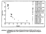
- Figure 2 shows the measured values with respect to the target quantities nitrogen oxide emission NOx and soot emission (soot number) RUSSZ depending on the influencing factors Injection start SB, boost pressure PL and intake manifold air temperature TL shown. It's closed recognize that the optimal values for the simultaneous minimization of both sizes with An injection start SB of -3 ° CA can be achieved. A more accurate analysis can be made to be developed in the models.
- the further evaluation is based on the target nitrogen oxide emission NOx shown.
- the evaluation runs for the two other target fuel consumption KRSTDS and Russemission ( Russians) RUSSZ analog.
- NOx a 0 + a SB * SB + a PL * PL + a AGR * AGR + a TL * TL + a MD * MD + a SB.PL * SB * PL + a SB.AGR * SB * AGR + a PL.AGR * PL * AGR + a TL.SB * TL * SB + a TL.PL * TL * PL + a TL.AGR * TL * AGR + a MD.SB * MD * SB + a MD.PL * MD * PL + a MD.AGR * MD * AGR + a MD.TL * MD * TL + a SB 2 * SB 2 + a PL 2 * PL 2 + a AGR 2 * AGR 2 + a TL 2 * TL 2 + a MD 2 * MD 2 * MD 2 * MD 2 + a MD 2 * MD 2 * MD 2 + a MD 2 * MD 2 * MD 2 + a MD 2 * MD 2 * MD 2 + a MD 2 * MD 2 *
- the mathematical function contains a total of 21 terms and correspondingly 21 free parameters, namely the coefficients a x of the quadratic polynomial.
- the values of the variables of the polynomial function for the nitrogen oxide emission NOx are respectively transformed to a uniform value range and normalized, in which the smallest adjusted set value f min is set equal to -1 and the largest set f max is set to +1.
- this normalizing transformation facilitates the comparison of the meaning of the individual terms for the target size result NOx, since the numerical value of the determined polynomial coefficients then directly reflects their significance for the target size result.
- the evaluation can also be carried out without such a normalizing transformation.
- the transformation does not have to be done for all variables; In the exemplary embodiment Beipiellus was omitted for the influence factor air temperature before the inlet valve TL and its square TL 2 on it (see Tables 7 and 8).
- NOx a 0 + a SB * SB + a PL * PL + a AGR * AGR + a TL * TL + a MD * MD + a TL.SB * TL * SB + a SB 2 * SB 2 + a PL 2 * PL 2 + a AGR 2 * AGR 2
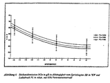
- Figure 6 shows the values obtained from the given formula Nitrogen oxide emission NOx as a function of the influencing factors injection start SB and mean boost pressure PL.
- the torque MD is usually stored in the memory unit in the form of a look-up table (just a numerical representation of the multi-dimensional characteristic field). Instead of storing the entire look-up table in the memory unit, now only the determined coefficients of the polynomial are stored in the memory unit.
Landscapes
- Engineering & Computer Science (AREA)
- Chemical & Material Sciences (AREA)
- Combustion & Propulsion (AREA)
- Mechanical Engineering (AREA)
- General Engineering & Computer Science (AREA)
- Nonlinear Science (AREA)
- Physics & Mathematics (AREA)
- Computer Hardware Design (AREA)
- Microelectronics & Electronic Packaging (AREA)
- Combined Controls Of Internal Combustion Engines (AREA)
- Testing Of Engines (AREA)
- Exhaust Gas After Treatment (AREA)
- Electrical Control Of Ignition Timing (AREA)
- Electrical Control Of Air Or Fuel Supplied To Internal-Combustion Engine (AREA)
Description
- Abbildung 1:
- Einfluß der Arbeitspunkte auf die Modellbildung;
- Abbildung 2:
- Abhängigkeiten der Ruß- und Stickoxidemissionen RUSSZ bzw. NOx von Einspritzbeginn SB, Ladedruck PL und Lufttemperatur im Saugrohr TL;
- Abbildung 3:
- Resultat unterschiedlicher Modellansätze für das Stickoxidemissions-Modell bei Berücksichtigung von 21 Funktionstermen;
- Abbildung 4:
- Wirkung der Haupteinflußfaktoren auf die Stickoxidemessionen NOx, mit 95 % Vertrauensintervall;
- Abbildung 5:
- Einfluß der Modellfunktionsterme auf die Stickoxidemession NOx;
- Abbildung 6:
- Stickoxidemession NOx in Abhängigkeit vom Kraftstoffeinspritzbeginn SB und Ladedruck PL, mit 95 % Vertrauensintervall;
- Abbildung 7:
- berechnetes Kennfeld für den Kraftstoffdurchsatz KRSTDS, die Stickoxid- und die Rußemissionen NOx bzw. RUSSZ in Abhängigkeit vom Ladedruck PL und Einspritzbeginn SB;
- Abbildung 8:
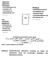
- zusammenfassende schematische Darstellung des Prinzips der erfinderischen Lösung einer beschleunigten Kennfeldwert- und Parameterwertermittlung.
| Liste der vor Versuchsbeginn im Modellansatz berücksichtigten Einflußfaktoren | |||
| Faktor | Abkürzung | Werte | Einheit |
| Kraftstoffeinspritzbeginn | SB | -15, -13, -11, -9, -7, -5, -3 | Kurbelwinkelgrade (°KW) vor oberem Totpunkt |
| mittlerer Ladedruck | PL | 1050, 1080, 1120, 1150 | mbar |
| Stellsignal für Abgasrückführungsventil | AGR | keine, gering, mittel, viel, maximal | |
| Lufttemperatur vor dem Einflußventil | TL | unkontrolliert | °C |

| Arbeitsplan für Motordrehzahl DRZ = 2000 min-1 und Ladedruck PL = 2 bar | |||
| Arbeitspunkt | Einspritzbeginn SB | Ladedruck PL | AGR-Rate AGR |
| Nr. | ºKW | mbar | |
| 1 | -15 | 1150 | viel |
| 2 | -15 | 1050 | keine |
| 3 | -15 | 1050 | mittel |
| 4 | -3 | 1050 | mittel |
| 5 | -3 | 1080 | gering |
| 6 | -15 | 1150 | keine |
| 7 | -3 | 1120 | maximal |
| 8 | -3 | 1050 | viel |
| 9 | -3 | 1050 | maximal |
| 10 | -15 | 1150 | mittel |
| 11 | -3 | 1150 | viel |
| 12 | -3 | 1150 | mittel |
| 13 | -15 | 1050 | gering |
| 14 | -9 | 1080 | viel |
| 15 | -15 | 1150 | maximal |
| 16 | -3 | 1150 | gering |
| 17 | -15 | 1050 | viel |
| 18 | -15 | 1150 | gering |
| 19 | -7 | 1150 | maximal |
| 20 | -3 | 1150 | keine |
| 21 | -15 | 1050 | maximal |
| 22 | -7 | 1050 | gering |
| 23 | -3 | 1050 | keine |
| Am Prüfstand gemessene Werte der Einflußfaktoren | ||||||||
| Arbeitspunkt | Einspritzbeginn SB | Ladedruck PL | AGR-Rate AGR | AGR-Rate AGR | Lufttemperatur am Ladeluftkühlerausgang TLAD | Lufttemperatur vor dem Einlaßventil TL | Drehzahl DRZ | Drehmoment MD |
| Nr. | °KW | mbar | % | °C | °C | min-1 | Nm | |
| 1 | -15 | 1150 | viel | 50 | 35.07 | 47.22 | 2000 | 29.2 |
| 2 | -15 | 1050 | keine | 80 | 36.41 | 40.59 | 2000 | 30.6 |
| 3 | -15 | 1050 | mittel | 60 | 34.1 | 38.65 | 2000 | 31.5 |
| 4 | -3 | 1050 | mittel | 60 | 33.16 | 38.24 | 2000 | 30.2 |
| 5 | -3 | 1080 | gering | 70 | 33.63 | 38.61 | 2000 | 30.8 |
| 6 | -15 | 1150 | keine | 80 | 36.62 | 39.54 | 2000 | 30.8 |
| 7 | -3 | 1120 | maximal | 40 | 36.12 | 65.31 | 2000 | 28.8 |
| 8 | -3 | 1050 | viel | 50 | 35.9 | 51.62 | 1999 | 30.9 |
| 9 | -3 | 1050 | maximal | 40 | 34.01 | 57.73 | 1999 | 30.4 |
| 10 | -15 | 1150 | mittel | 60 | 36.99 | 42.99 | 2000 | 30.7 |
| 11 | -3 | 1150 | viel | 50 | 37.79 | 46.08 | 2003 | 30.2 |
| 12 | -3 | 1150 | mittel | 60 | 38.81 | 42.9 | 2004 | 30.7 |
| 13 | -15 | 1050 | gering | 75 | 34.89 | 39.2 | 2004 | 29.6 |
| 14 | -9 | 1080 | viel | 51 | 34.42 | 40.88 | 2004 | 30.8 |
| 15 | -15 | 1115 | maximal | 40 | 35.27 | 74.17 | 2004 | 29.5 |
| 16 | -3 | 1150 | gering | 70 | 38.03 | 42.82 | 2003 | 29.2 |
| 17 | -15 | 1050 | viel | 50 | 36.54 | 43.16 | 2003 | 31.3 |
| 18 | -15 | 1147 | gering | 70 | 38.21 | 40.5 | 2003 | 30.5 |
| 19 | -7 | 1118 | maximal | 40 | 36.94 | 75.11 | 2003 | 29.5 |
| 20 | -3 | 1150 | keine | 80 | 39.32 | 42.38 | 2004 | 30.5 |
| 21 | -15 | 1054 | maximal | 40 | 36.42 | 60.13 | 2003 | 30.4 |
| 22 | -7 | 1050 | gering | 70 | 35.86 | 40.83 | 2003 | 30.1 |
| 23 | -3 | 1053 | keine | 80 | 35.2 | 39.84 | 2003 | 29.8 |
| Am Prüfstand gemessene Zielgrößen (RUSSZ = Rußzahl, NOx = Stickoxide in ppm, KRSTDS = Kraftstoffdurchsatz in kg/h, AROIST = Luftdurchsatz in kg/h aus dem Signal des Heißfilmsensors) | ||||
| Arbeitspunkt | Russzahl RUSSZ | Stickoxide NOx | Kraftstoffverbrauch KRSTDS | Luftdurchsatz AROIST |
| Nr. | 1 | ppm | kg/h | kg/h |
| 1 | 0.305 | 372 | 2.07 | 111 |
| 2 | 0.285 | 429 | 2.03 | 120 |
| 3 | 0.295 | 429 | 2.13 | 120 |
| 4 | 0.695 | 155 | 2.18 | 121 |
| 5 | 0.675 | 157 | 2.16 | 123 |
| 6 | 0.255 | 394 | 2.12 | 131 |
| 7 | 1.602 | 90 | 2.23 | 77 |
| 8 | 0.915 | 150 | 2.19 | 106 |
| 9 | 1.103 | 124 | 2.18 | 89 |
| 10 | 0.275 | 389 | 2.09 | 127 |
| 11 | 0.825 | 146 | 2.3 | 116 |
| 12 | 0.725 | 151 | 2.3 | 129 |
| 13 | 0.255 | 414 | 1.97 | 120 |
| 14 | 0.725 | 207 | 2.16 | 115 |
| 15 | 1.335 | 189 | 2.17 | 71 |
| 16 | 0.735 | 149 | 2.14 | 131 |
| 17 | 0.365 | 396 | 2.07 | 109 |
| 18 | 0.265 | 394 | 2.11 | 130 |
| 19 | 2.66 | 85 | 2.23 | 70 |
| 20 | 0.755 | 153 | 2.25 | 131 |
| 21 | 0.665 | 304 | 2.09 | 82 |
| 22 | 0.765 | 186 | 2.25 | 120 |
| 23 | 0.655 | 156 | 2.22 | 121 |
| Lineare Korrelationsanalyse der Variablen (aus 23 von 23 Arbeitspunkten) | |||||||||
| SB | PL | AGR | MD | TLAD | TL | KRSTDS | NOx | RUSSZ | |
| SB | 1.000 | 0.030 | -0.026 | -0.197 | 0.048 | 0.027 | 0.766 | -0.796 | 0.435 |
| PL | 0.030 | 1.000 | 0.039 | -0.288 | 0.663 | 0.095 | 0.265 | 0.009 | 0.081 |
| AGR | -0.026 | 0.039 | 1.000 | 0.189 | 0.184 | -0.764 | -0.184 | 0.471 | -0.569 |
| MD | -0.197 | -0.288 | 0.189 | 1.000 | -0.041 | -0.477 | -0.090 | 0.425 | -0.464 |
| TLAD | 0.048 | 0.663 | 0.184 | -0.041 | 1.000 | 0.031 | 0.269 | 0.047 | 0.040 |
| TL | 0.027 | 0.095 | -0.764 | -0.477 | 0.031 | 1.000 | 0.219 | -0.566 | 0.818 |
| KRSTDS | 0.766 | 0.265 | -0.184 | -0.090 | 0.269 | 0.219 | 1.000 | -0.721 | 0.533 |
| NOx | -0.796 | 0.009 | 0.471 | 0.425 | 0.047 | -0.566 | -0.721 | 1.000 | -0.780 |
| RUSSZ | 0.435 | 0.081 | -0.569 | -0.464 | 0.040 | 0.818 | 0.533 | -0.780 | 1.000 |
| Werte sind signifikant verschieden von 0 (mit 95 % wenn sie in absoluten Zahlen größer als 0.413 |
| Vollständiges Modell für den Massenstrom der Stickoxidemission | ||||
| Koeffizienten für LS, Zielgröße NOX, | ||||
| Term | Koeff, ax | Std.abw. | T-Wert | Signif. |
| 1 1 | 116.836004 | 89.633137 | 1.30 | 0.3223 |
| 2 -SB | -55.133720 | 5.604357 | -9.84 | 0.0102 |
| 3 -PL | 22.144801 | 27.824673 | 0.80 | 0.5096 |
| 4 -AGR | 1.167346 | 49.049756 | 0.02 | 0.9832 |
| 5 -MD | 20.140600 | 27.008276 | 0.75 | 0.5336 |
| 6 -SB*PL | -0.582767 | 0.583164 | -1.00 | 0.4229 |
| 7 -SB*AGR | 1.074790 | 1.319033 | 0.81 | 0.5008 |
| 8 -SB*MD | -0.450068 | 1.425292 | -0.32 | 0.7821 |
| 9 -PL*AGR | -2.758707 | 2.443391 | -1.13 | 0.3761 |
| 10 -PL*MD | -2.112677 | 2.151024 | -0.98 | 0.4296 |
| 11 -AGR*MD | -0.446591 | 4.643464 | -0.10 | 0.9321 |
| 12 -SB**2 | 9.256800 | 2.377801 | 3.89 | 0.0601 |
| 13 -PL**2 | 6.575369 | 3.261768 | 2.02 | 0.1814 |
| 14 -AGR**2 | -4.224712 | 3.401141 | -1.24 | 0.3401 |
| 15 -MD**2 | -3.627114 | 3.457786 | -1.05 | 0.4043 |
| 16 -TL | -2.425010 | 3.837210 | -0.63 | 0.5920 |
| 17 -TL**2 | 0.015405 | 0.040613 | 0.38 | 0.7410 |
| 18 -TL*SB | 0.716589 | 0.117707 | 6.09 | 0.0259 |
| 19 -TL*PL | -0.444439 | 0.653277 | -0.68 | 0.5665 |
| 20 -TL*AGR | 0.096197 | 1.086991 | 0.09 | 0.9375 |
| 21 -TL*MD | -0.372205 | 0.597656 | -0.62 | 0.5970 |
| Modell für die Stickoxidemissionen NOx mit allen signifikanten Termen | ||||
| Koeffizienten für LS, Zielgröße NOX | ||||
| Term | Koeff. ax | Std.abw. | T-Wert | Signif. |
| 1 1 | 72.478644 | 4.803930 | 15.09 | 0.0001 |
| 2 -SB | -51.674042 | 1.931396 | -26.75 | 0.0001 |
| 3 -PL | 1.812678 | 0.460408 | 3.94 | 0.0017 |
| 4 -AGR | 6.898174 | 1.196411 | 5.77 | 0.0001 |
| 5 -MD | 2.554958 | 0.665147 | 3.84 | 0.0020 |
| 6 -SB**2 | 8.185808 | 1.341441 | 6.10 | 0.0001 |
| 7 -PL**2 | 4.212964 | 1.419855 | 2.97 | 0.0109 |
| 8 -AGR**2 | -4.938841 | 1.577394 | -3.13 | 0.0080 |
| 9 -TL | -0.676348 | 0.101358 | -6.67 | 0.0001 |
| 10 -TL*SB | 0.635087 | 0.040353 | 15.74 | 0.0001 |
| Ergebnis einer Optimierung des Kraftstoffdurchsatzes KRSTDS mit der Beschränkung der Stickoxidemissionen NOx auf NOx < 30 g/h | |||
| Faktoren, Zielgrößen | Bereich | Startwerte | Optimum |
| 1 Faktoren | |||
| 2 SPRITZBEGINN | -15 to -3 | -12 | -3.005 |
| 3 LADEDRUCK | 1050 to 1150 | 1100 | 1095.8 |
| 4 ABGASRUECKFUEHR | 40 to 80 | 60 | 40.169 |
| 5 MOMENT | 30 | 30 | |
| 6 T_EINLASS | 38.24 to 75.11 | 56.67 | 41.47 |
| 7 | |||
| 8 Zielgrößen | |||
| 9 VERBRAUCH | MIN | 2.0919 | |
| 10 NOX | <30 | 15.461 | |
| 11 PARTIKEL | 1.2378 | ||
| 12 RUSS | 0.71468 |
Claims (18)
- Verfahren zur Bestimmung von einem oder mehreren Parametern für eine oder mehrere mathematische Funktionen zur Steuerung eines Verbrennungsmotors, wobeidadurch gekennzeichnet, dass nach der Berechnung der Parameter der einen oder mehreren Funktion(en) der einen oder mehreren Zielgröße(n) überprüft wird, welche Einflussfaktoren jeweils nur einen im Rahmen der geforderten Genauigkeit vernachlässigbaren Einfluss auf die eine oder mehreren Zielgröße(n) haben, und diese bestimmten, vernachlässigbaren Einflussfaktoren daraufhin in der jeweils betrachteten Funktion nicht mehr berücksichtigt werden.einer oder mehreren Zielgröße(n) jeweils eine mathematische Funktion von jeweils einem oder mehreren Einflussfaktor(en) zugeordnet wird, wobei die Funktion jeweils eine Abhängigkeit der Zielgröße(n) von dem bzw. den Einflussfaktor(en) anhand eines oder mehrerer Parameter beschreibt,in experimentellen Versuchen ein oder mehrere Messwert(e) für den Verbrennungsmotor gemessen wird bzw. werden, wobei die Anzahl der Messwerte mindestens gleich der maximalen Anzahl der in einer verwendeten Funktion vorkommenden Parameter ist, undanschließend anhand der Messwerte die Parameter für die eine oder mehreren mathematischen Funktion(en) der einen oder mehreren Einflussfaktoren berechnet werden,
- Verfahren nach Anspruch 1, dadurch gekennzeichnet, dass sukzessive der jeweils am meisten vernachlässigbare Einflussfaktor - d.h. der Einflussfaktor mit der geringsten Bedeutung für die jeweilige Zielgröße - bestimmt wird und anschließend die Berechnung der Parameter der jeweiligen Funktion für die jeweilige Zielgröße unter Weglassung des derart bestimmten Einflussfaktors wiederholt wird.
- Verfahren nach Anspruch 1 oder 2, dadurch gekennzeichnet, dass die eine oder mehrere mathematische Funktion(en) als zusätzliche Terme einfache Produkte von Einflussfaktoren aufweisen, denen jeweils ein Parameter zugeordnet ist, und überprüft wird, welche Produkte von Einflussfaktoren jeweils nur einen im Rahmen einer geforderten Genauigkeit vernachlässigbaren Einfluss auf die eine oder mehreren Zielgrößen haben, und diese bestimmten, vemachlässigbaren Produkte von Einflussfaktoren daraufhin in der jeweils betrachteten Funktion nicht mehr berücksichtigt werden.
- Verfahren nach einem der vorhergehenden Ansprüche, dadurch gekennzeichnet, dass die eine oder mehreren Zielgröße(n)sind.der Treibstoffverbrauch KRSTDS und/oderdie Stickoxid-Emission NOx und/oderdie Rußemission RUSSZ
- Verfahren nach einem der vorhergehenden Ansprüche, dadurch gekennzeichnet, dass die Einflussfaktoren kontrollierbare Einflussfaktoren und/oder nicht kontrollierbare Einflussfaktoren sind.
- Verfahren nach Anspruch 5, dadurch gekennzeichnet, dass die kontrollierbaren Einflussfaktorensind.der Kraftstoffeinspritzbeginn SB und/oderder mittlere Ladedruck PL und/oderdie Abgasrückführrate AGR und/oderdas Drehmoment MD und/oderdie Motordrehzahl DRZ
- Verfahren nach Anspruch 5 oder 6, dadurch gekennzeichnet, dass die nicht kontrollierbaren Einflussfaktorensind.die Lufttemperatur im Saugrohr vor dem Einlassventil TL und/oderdie Lufttemperatur am Ausgang des Ladeluftkühlers TLAD und/oderdie Kühlwassertemperatur TW
- Verfahren nach einem der vorhergehenden Ansprüche, dadurch gekennzeichnet, dass die Anzahl der Messwerte größer als die maximale Anzahl der in einer verwendeten Funktion vorkommenden Parameter ist, um mittels an sich bekannter statistischer Methoden, insbesondere statistischer Ausgleichsverfahren, die Anpassgenauigkeit der Parameter zu erhöhen.
- Verfahren nach Anspruch 8, dadurch gekennzeichnet, dass das verwendete statistische Ausgleichsverfahren das Verfahren der kleinsten Quadrate mittels einer Regressionsgerade ist.
- Verfahren nach einem der vorhergehenden Ansprüche, dadurch gekennzeichnet, dass die mathematische Funktionein Polynom ist und/odereine Exponential-Funktion ist, wobei das Argument der Exponential-Funktion ein Polynom ist, und/odereine logarithmische Funktion ist, wobei das Argument der logarithmischen Funktion ein Polynom ist, und/odereine quadratische Funktion ist, wobei das Argument der quadratischen Funktion ein Polynom ist, und/odereine inverse Funktion ist, wobei das Argument der inversen Funktion ein Polynom ist, und/odereine Wurzelfunktion ist, wobei das Argument der Wurzelfunktion ein Polynom ist, und/odereine inverse Wurzelfunktion ist, wobei das Argument der inversen Wurzelfunktion ein Polynom ist.
- Verfahren nach Anspruch 10, dadurch gekennzeichnet, dass das Polynom ein quadratisches Polynom einer oder mehrerer Variablen ist, wobei die Variablen die Einflussfaktoren sind.
- Verfahren nach Anspruch 10 oder 11, dadurch gekennzeichnet, dass die Parameter die Koeffizienten des Polynoms sind.
- Verfahren nach Anspruch 1, dadurch gekennzeichnet, dass vor Beginn der experimentellen Messungen für einige oder jeden experimentell kontrollierbaren Einflussfaktor ein kleinster Einstellwert fmin sowie ein größter Einstellwert fmax festgelegt werden und zwischen diesen Werten fmin und fmax kein, ein oder mehrere weitere Zwischeneinstellwerte zur Messung festgelegt werden.
- Verfahren nach Anspruch 13, dadurch gekennzeichnet, dass die Zwischeneinstellwerte äquidistant festgelegt werden.
- Verfahren nach Anspruch 13 oder 14, dadurch gekennzeichnet, dass die Einstellwerte mehrerer oder aller Einflussfaktoren zur besseren Vergleichbarkeit der Parameter dahingehend normiert werden, dass ihr kleinster einzustellender Wert fmin jeweils gleich einem bestimmten, übereinstimmenden numerischen Wert - insbesondere 0 oder -1 - gesetzt wird, während ihr größter einzustellender Wert fmax jeweils gleich einem anderen, übereinstimmenden numerischen Wert - insbesondere +1 - gesetzt wird.
- Verfahren nach Anspruch 1, dadurch gekennzeichnet, dass während der experimentellen Messungen ein oder mehrere weitere mögliche Einflussgrößen jeweils mitgemessen werden und - sofern sich bei der Auswertung der Messungen erweist, dass diese möglichen Einflussgrößen einen im Rahmen der geforderten Genauigkeit nicht vernachlässigbaren Einfluss auf eine oder mehrere Zielgrößen haben - zumindest diese nicht vernachlässigbaren weiteren Einflussgrößen dann als Einflussfaktoren in die mathematische(n) Funktion(en) der einen oder mehreren Zielgrößen einbezogen werden.
- Verfahren nach einem der vorhergehenden Ansprüche, dadurch gekennzeichnet, dass die Zielgrößensind.das Drehmoment MD und/oderdie Katalysatortemperatur TKAT und/oderdie Abgastemperatur TA
- Verfahren nach einem der vorhergehenden Ansprüche, dadurch gekennzeichnet, dass die Einflussfaktorensinddie Drehzahl DRZ und/oderder Lambda-Wert LAMA und/oderder Zündwinkel ZWOUT und/oderdie Last RLW und/oderder mittlere Ladedruck PL
Applications Claiming Priority (3)
| Application Number | Priority Date | Filing Date | Title |
|---|---|---|---|
| DE19819445A DE19819445A1 (de) | 1998-04-30 | 1998-04-30 | Verfahren zur Bestimmung von Kennfelddaten zur Kennfeldsteuerung eines Verbrennungsmotors sowie Verfahren zur Steuerung eines Verbrennungsmotors |
| DE19819445 | 1998-04-30 | ||
| EP99916846A EP1075594B1 (de) | 1998-04-30 | 1999-03-22 | Verfahren zur bestimmung von kennfelddaten zur kennfeldsteuerung eines verbrennungsmotors |
Related Parent Applications (1)
| Application Number | Title | Priority Date | Filing Date |
|---|---|---|---|
| EP99916846A Division EP1075594B1 (de) | 1998-04-30 | 1999-03-22 | Verfahren zur bestimmung von kennfelddaten zur kennfeldsteuerung eines verbrennungsmotors |
Publications (3)
| Publication Number | Publication Date |
|---|---|
| EP1273782A2 EP1273782A2 (de) | 2003-01-08 |
| EP1273782A3 EP1273782A3 (de) | 2003-03-05 |
| EP1273782B1 true EP1273782B1 (de) | 2005-03-16 |
Family
ID=7866357
Family Applications (2)
| Application Number | Title | Priority Date | Filing Date |
|---|---|---|---|
| EP99916846A Expired - Lifetime EP1075594B1 (de) | 1998-04-30 | 1999-03-22 | Verfahren zur bestimmung von kennfelddaten zur kennfeldsteuerung eines verbrennungsmotors |
| EP02022273A Expired - Lifetime EP1273782B1 (de) | 1998-04-30 | 1999-03-22 | Verfahren zur Bestimmung von Kennfelddaten zur Kennfeldsteuerung eines Verbrennungsmotors sowie Verfahren zur Steuerung eines Verbrennungsmotors |
Family Applications Before (1)
| Application Number | Title | Priority Date | Filing Date |
|---|---|---|---|
| EP99916846A Expired - Lifetime EP1075594B1 (de) | 1998-04-30 | 1999-03-22 | Verfahren zur bestimmung von kennfelddaten zur kennfeldsteuerung eines verbrennungsmotors |
Country Status (5)
| Country | Link |
|---|---|
| EP (2) | EP1075594B1 (de) |
| AT (2) | ATE242425T1 (de) |
| DE (3) | DE19819445A1 (de) |
| ES (1) | ES2199569T3 (de) |
| WO (1) | WO1999057426A1 (de) |
Families Citing this family (12)
| Publication number | Priority date | Publication date | Assignee | Title |
|---|---|---|---|---|
| DE10202156B4 (de) * | 2002-01-22 | 2010-08-26 | Volkswagen Ag | Verfahren zum Betreiben einer Brennkraftmaschine |
| DE10259851B4 (de) * | 2002-12-17 | 2015-06-25 | Iav Gmbh Ingenieurgesellschaft Auto Und Verkehr | Verfahren zur Kennlinienadaption eines im Steuergerät eines Kraftfahrzeuges gespeicherten Kennlinienfeldes |
| AT6235U3 (de) | 2003-02-28 | 2004-01-26 | Avl List Gmbh | Verfahren zur steuerung eines prüfstandes |
| CN100398799C (zh) * | 2004-10-20 | 2008-07-02 | 北京交通大学 | 一种天然气发动机电控多点顺序喷射系统的控制方法 |
| EP2128727A1 (de) * | 2008-05-29 | 2009-12-02 | Continental Automotive GmbH | Verfahren und Computerprogrammprodukt zur Bereitstellung eines speicherplatzreduzierten Steuerprogrammes |
| DE102009024544A1 (de) | 2009-06-08 | 2010-12-30 | Fev Motorentechnik Gmbh | Automatisierte Bedatung eines Ottomotors |
| DE102009059931A1 (de) * | 2009-12-22 | 2011-06-30 | Volkswagen AG, 38440 | Ermitteln und Parametrieren von Polynom-Modellen für Verbrennungsmotoren |
| DE102010060992A1 (de) * | 2010-12-02 | 2012-06-06 | Fev Gmbh | Ladedruckgeführtes Regelverfahren für eine Brennkraftmaschine |
| AT508817B1 (de) * | 2010-12-06 | 2011-10-15 | Avl List Gmbh | Verfahren und anordnung zur bestimmung eines rauchbegrenzungskennfeldes eines verbrennungsmotors |
| DE102012014469A1 (de) | 2012-07-23 | 2014-05-15 | Fev Gmbh | Verbesserte Versuchsdurchführung |
| DE102018209851B4 (de) | 2018-06-19 | 2023-09-28 | Audi Ag | Verfahren zum Betreiben einer Brennkraftmaschine sowie entsprechende Brennkraftmaschine |
| DE102018217139B4 (de) * | 2018-10-08 | 2020-06-18 | Audi Ag | Verfahren und Vorrichtung zum Konfigurieren einer Kennfunktion eines Steuergeräts eines Kraftfahrzeugs |
Family Cites Families (16)
| Publication number | Priority date | Publication date | Assignee | Title |
|---|---|---|---|---|
| JPS5832936A (ja) * | 1981-08-21 | 1983-02-26 | Nissan Motor Co Ltd | 燃料噴射量計測装置 |
| JPS59183040A (ja) * | 1983-04-04 | 1984-10-18 | Toyota Motor Corp | 内燃機関の燃料供給量制御装置 |
| DE3408223A1 (de) * | 1984-02-01 | 1985-08-01 | Robert Bosch Gmbh, 7000 Stuttgart | Steuer- und regelverfahren fuer die betriebskenngroessen einer brennkraftmaschine |
| US4903668A (en) * | 1987-07-29 | 1990-02-27 | Toyota Jidosha Kabushiki Kaisha | Fuel injection system of an internal combustion engine |
| US5170475A (en) * | 1989-03-06 | 1992-12-08 | Motorola, Inc. | Data processor having instructions for interpolating between memory-resident data values respectively |
| US4903669A (en) * | 1989-04-03 | 1990-02-27 | General Motors Corporation | Method and apparatus for closed loop fuel control |
| DE4007548A1 (de) * | 1990-03-09 | 1991-09-12 | Bosch Gmbh Robert | Verfahren zum bestimmen des integrationsanteils des stellwertes bei einer digitalen lambdaregelung |
| IT1250986B (it) * | 1991-07-26 | 1995-04-27 | Weber Srl | Sistema con controllo adattativo della quantita' di benzina iniettata per un sistema di iniezione elettronica |
| DE4304441B4 (de) * | 1993-02-13 | 2012-02-16 | Robert Bosch Gmbh | Verfahren zum Betreiben eines Prozesses mit Hilfe eines Kennfeldes |
| JPH07293297A (ja) * | 1994-04-20 | 1995-11-07 | Hitachi Ltd | 内燃機関の燃料制御方法及びその装置、並びにそれを用いた車両 |
| DE4428818B4 (de) * | 1994-08-13 | 2006-01-12 | Deutz Ag | Verfahren zur Einstellung einer serienmäßig hergestellten Brennkraftmaschaschine |
| DE4434455A1 (de) * | 1994-09-27 | 1996-03-28 | En Umwelt Beratung E V I | Verfahren zur Bestimmung spezifischer Betriebskennwerte einer Maschine insbesondere spezifischer Verbrauchskennwerte einer Brennkraftmaschine mittels meßwertgestützter, induktiv selbstlernender Berechnung während des Fahrbetriebs |
| DE19527112C1 (de) * | 1995-07-25 | 1996-09-19 | Forschungsgesellschaft Kraftfa | Verfahren zur Kalibrierung eines Kennfeldes einer Antriebsmaschine |
| US5629481A (en) * | 1995-09-06 | 1997-05-13 | General Motors Corporation | Mass air flow measurement system and method |
| GB2314172B (en) * | 1996-06-15 | 2000-08-16 | Luk Getriebe Systeme Gmbh | Motor vehicle |
| IT1286101B1 (it) * | 1996-06-17 | 1998-07-07 | Same Spa Ora Same Deutz Fahr S | Dispositivo elettronico di regolazione della velocita' di rotazione del motore di una trattrice agricola |
-
1998
- 1998-04-30 DE DE19819445A patent/DE19819445A1/de not_active Withdrawn
-
1999
- 1999-03-22 EP EP99916846A patent/EP1075594B1/de not_active Expired - Lifetime
- 1999-03-22 AT AT99916846T patent/ATE242425T1/de not_active IP Right Cessation
- 1999-03-22 DE DE59905849T patent/DE59905849D1/de not_active Expired - Lifetime
- 1999-03-22 AT AT02022273T patent/ATE291163T1/de active
- 1999-03-22 DE DE59911779T patent/DE59911779D1/de not_active Expired - Lifetime
- 1999-03-22 EP EP02022273A patent/EP1273782B1/de not_active Expired - Lifetime
- 1999-03-22 WO PCT/EP1999/001882 patent/WO1999057426A1/de not_active Ceased
- 1999-03-22 ES ES99916846T patent/ES2199569T3/es not_active Expired - Lifetime
Also Published As
| Publication number | Publication date |
|---|---|
| ATE291163T1 (de) | 2005-04-15 |
| EP1273782A3 (de) | 2003-03-05 |
| ES2199569T3 (es) | 2004-02-16 |
| DE59911779D1 (de) | 2005-04-21 |
| EP1075594A1 (de) | 2001-02-14 |
| WO1999057426A1 (de) | 1999-11-11 |
| EP1273782A2 (de) | 2003-01-08 |
| DE19819445A1 (de) | 1999-11-04 |
| ATE242425T1 (de) | 2003-06-15 |
| DE59905849D1 (de) | 2003-07-10 |
| EP1075594B1 (de) | 2003-06-04 |
Similar Documents
| Publication | Publication Date | Title |
|---|---|---|
| DE3874585T2 (de) | Verfahren zur vorausberechnung der parameter zur steuerung der kraftstoffzufuhr fuer eine brennkraftmaschine. | |
| DE112005001710B4 (de) | Verfahren zur Untersuchung des Verhaltens von komplexen Systemen, insbesondere von Brennkraftmaschinen | |
| DE102018001727B4 (de) | Verfahren zur modellbasierten Steuerung und Regelung einer Brennkraftmaschine | |
| DE112005003527B4 (de) | Verfahren für die Schätzung von Verbrennungsparametern | |
| DE112007001865T5 (de) | Verfahren und Vorrichtung zum Schätzen des Abgasdrucks einer Brennkraftmaschine | |
| WO2014015974A2 (de) | Verbesserte versuchsdurchführung | |
| DE102007003245A1 (de) | Verfahren zum Entwerfen eines Motorkomponenten-Temperaturschätzers | |
| EP1075594B1 (de) | Verfahren zur bestimmung von kennfelddaten zur kennfeldsteuerung eines verbrennungsmotors | |
| EP3499011B1 (de) | Verfahren und steuervorrichtung zum bestimmen eines soll-saugrohrdrucks einer verbrennungskraftmaschine | |
| DE102017105866A1 (de) | Überwachungsmodell-Vorhersagesteuerung in einer Motoranordnung | |
| DE19706750A1 (de) | Verfahren zur Gemischsteuerung bei einem Verbrennungsmotor sowie Vorrichtung zu dessen Durchführung | |
| EP4139761A1 (de) | Verfahren zum betreiben eines steuergeräts für ein kraftfahrzeug sowie entsprechendes steuergerät | |
| DE4018800A1 (de) | Verfahren und vorrichtung zur bestimmung der steuerwerte eines mehrzylinder-verbrennungsmotors | |
| DE102004026006B4 (de) | Steuergerät und Steuerverfahren für eine Brennkraftmaschine | |
| EP2162802B1 (de) | Verfahren und vorrichtung zum betreiben einer verbrennungskraftmaschine | |
| DE102010046491B4 (de) | Verfahren zum Bestimmen einer Schadstoffemission im Brennraum eines Dieselmotors | |
| DE69307282T2 (de) | Verfahren zur Steuerung der Abgasrückführung bei einer Brennkraftmaschine | |
| DE102016200782A1 (de) | Verfahren und Vorrichtung zum Bestimmen einer Gasführungssystemgröße in einem Motorsystem mit einem Verbrennungsmotor | |
| DE102018006312B4 (de) | Verfahren zur modellbasierten Steuerung und Regelung einer Brennkraftmaschine | |
| EP2019195B1 (de) | Verfahren zur Bestimmung der eingespritzten Kraftstoffmenge | |
| DE102020126891B4 (de) | Steuermodul und Verfahren zum Steuern eines Luftaufladungssystems eines Fahrzeugs | |
| EP3181875A1 (de) | Referenzbasiertes saugrohrtemperaturmodell | |
| DE102019005996B4 (de) | Verfahren zur modellbasierten Steuerung und Regelung einer Brennkraftmaschine | |
| DE102022104648A1 (de) | Automatisierte funktionskalibrierung | |
| DE112009000324B4 (de) | Verfahren und Computerprogrammprodukt zum Abgleichen eines Luftmassenstromsensors einer Motoranordnung eines Kraftfahrzeugs |
Legal Events
| Date | Code | Title | Description |
|---|---|---|---|
| PUAI | Public reference made under article 153(3) epc to a published international application that has entered the european phase |
Free format text: ORIGINAL CODE: 0009012 |
|
| AC | Divisional application: reference to earlier application |
Ref document number: 1075594 Country of ref document: EP |
|
| AK | Designated contracting states |
Kind code of ref document: A2 Designated state(s): AT DE ES FR GB IT PT SE |
|
| PUAL | Search report despatched |
Free format text: ORIGINAL CODE: 0009013 |
|
| AK | Designated contracting states |
Designated state(s): AT DE ES FR GB IT PT SE Kind code of ref document: A3 Designated state(s): AT DE ES FR GB IT PT SE |
|
| 17P | Request for examination filed |
Effective date: 20030905 |
|
| 17Q | First examination report despatched |
Effective date: 20031008 |
|
| AKX | Designation fees paid |
Designated state(s): AT DE ES FR GB IT PT SE |
|
| GRAP | Despatch of communication of intention to grant a patent |
Free format text: ORIGINAL CODE: EPIDOSNIGR1 |
|
| GRAS | Grant fee paid |
Free format text: ORIGINAL CODE: EPIDOSNIGR3 |
|
| GRAA | (expected) grant |
Free format text: ORIGINAL CODE: 0009210 |
|
| AC | Divisional application: reference to earlier application |
Ref document number: 1075594 Country of ref document: EP Kind code of ref document: P |
|
| AK | Designated contracting states |
Kind code of ref document: B1 Designated state(s): AT DE ES FR GB IT PT SE |
|
| PG25 | Lapsed in a contracting state [announced via postgrant information from national office to epo] |
Ref country code: ES Free format text: LAPSE BECAUSE OF FAILURE TO SUBMIT A TRANSLATION OF THE DESCRIPTION OR TO PAY THE FEE WITHIN THE PRESCRIBED TIME-LIMIT Effective date: 20050316 Ref country code: GB Free format text: LAPSE BECAUSE OF FAILURE TO SUBMIT A TRANSLATION OF THE DESCRIPTION OR TO PAY THE FEE WITHIN THE PRESCRIBED TIME-LIMIT Effective date: 20050316 |
|
| REG | Reference to a national code |
Ref country code: GB Ref legal event code: FG4D Free format text: NOT ENGLISH |
|
| REF | Corresponds to: |
Ref document number: 59911779 Country of ref document: DE Date of ref document: 20050421 Kind code of ref document: P |
|
| PG25 | Lapsed in a contracting state [announced via postgrant information from national office to epo] |
Ref country code: PT Free format text: LAPSE BECAUSE OF FAILURE TO SUBMIT A TRANSLATION OF THE DESCRIPTION OR TO PAY THE FEE WITHIN THE PRESCRIBED TIME-LIMIT Effective date: 20050907 |
|
| GBV | Gb: ep patent (uk) treated as always having been void in accordance with gb section 77(7)/1977 [no translation filed] |
Effective date: 20050316 |
|
| PLBE | No opposition filed within time limit |
Free format text: ORIGINAL CODE: 0009261 |
|
| STAA | Information on the status of an ep patent application or granted ep patent |
Free format text: STATUS: NO OPPOSITION FILED WITHIN TIME LIMIT |
|
| 26N | No opposition filed |
Effective date: 20051219 |
|
| EN | Fr: translation not filed | ||
| PG25 | Lapsed in a contracting state [announced via postgrant information from national office to epo] |
Ref country code: SE Free format text: LAPSE BECAUSE OF FAILURE TO SUBMIT A TRANSLATION OF THE DESCRIPTION OR TO PAY THE FEE WITHIN THE PRESCRIBED TIME-LIMIT Effective date: 20050616 |
|
| PG25 | Lapsed in a contracting state [announced via postgrant information from national office to epo] |
Ref country code: FR Free format text: LAPSE BECAUSE OF NON-PAYMENT OF DUE FEES Effective date: 20050331 |
|
| PG25 | Lapsed in a contracting state [announced via postgrant information from national office to epo] |
Ref country code: FR Free format text: LAPSE BECAUSE OF NON-PAYMENT OF DUE FEES Effective date: 20050316 |
|
| PGFP | Annual fee paid to national office [announced via postgrant information from national office to epo] |
Ref country code: AT Payment date: 20140328 Year of fee payment: 16 Ref country code: IT Payment date: 20140328 Year of fee payment: 16 |
|
| REG | Reference to a national code |
Ref country code: AT Ref legal event code: MM01 Ref document number: 291163 Country of ref document: AT Kind code of ref document: T Effective date: 20150322 |
|
| PG25 | Lapsed in a contracting state [announced via postgrant information from national office to epo] |
Ref country code: IT Free format text: LAPSE BECAUSE OF NON-PAYMENT OF DUE FEES Effective date: 20150322 |
|
| PG25 | Lapsed in a contracting state [announced via postgrant information from national office to epo] |
Ref country code: AT Free format text: LAPSE BECAUSE OF NON-PAYMENT OF DUE FEES Effective date: 20150322 |
|
| PGFP | Annual fee paid to national office [announced via postgrant information from national office to epo] |
Ref country code: DE Payment date: 20180331 Year of fee payment: 20 |
|
| REG | Reference to a national code |
Ref country code: DE Ref legal event code: R071 Ref document number: 59911779 Country of ref document: DE |