EP1273888A2 - Erfassungseinrichtung für ein Fluid und Verfahren zur Ermittlung des Wechsels einer Fluidart - Google Patents
Erfassungseinrichtung für ein Fluid und Verfahren zur Ermittlung des Wechsels einer Fluidart Download PDFInfo
- Publication number
- EP1273888A2 EP1273888A2 EP02013939A EP02013939A EP1273888A2 EP 1273888 A2 EP1273888 A2 EP 1273888A2 EP 02013939 A EP02013939 A EP 02013939A EP 02013939 A EP02013939 A EP 02013939A EP 1273888 A2 EP1273888 A2 EP 1273888A2
- Authority
- EP
- European Patent Office
- Prior art keywords
- fluid
- detection device
- values
- measured values
- stored
- Prior art date
- Legal status (The legal status is an assumption and is not a legal conclusion. Google has not performed a legal analysis and makes no representation as to the accuracy of the status listed.)
- Withdrawn
Links
Images
Classifications
-
- G—PHYSICS
- G01—MEASURING; TESTING
- G01D—MEASURING NOT SPECIALLY ADAPTED FOR A SPECIFIC VARIABLE; ARRANGEMENTS FOR MEASURING TWO OR MORE VARIABLES NOT COVERED IN A SINGLE OTHER SUBCLASS; TARIFF METERING APPARATUS; MEASURING OR TESTING NOT OTHERWISE PROVIDED FOR
- G01D4/00—Tariff metering apparatus
- G01D4/002—Remote reading of utility meters
-
- G—PHYSICS
- G01—MEASURING; TESTING
- G01F—MEASURING VOLUME, VOLUME FLOW, MASS FLOW OR LIQUID LEVEL; METERING BY VOLUME
- G01F1/00—Measuring the volume flow or mass flow of fluid or fluent solid material wherein the fluid passes through a meter in a continuous flow
- G01F1/66—Measuring the volume flow or mass flow of fluid or fluent solid material wherein the fluid passes through a meter in a continuous flow by measuring frequency, phase shift or propagation time of electromagnetic or other waves, e.g. using ultrasonic flowmeters
- G01F1/662—Constructional details
-
- G—PHYSICS
- G01—MEASURING; TESTING
- G01F—MEASURING VOLUME, VOLUME FLOW, MASS FLOW OR LIQUID LEVEL; METERING BY VOLUME
- G01F1/00—Measuring the volume flow or mass flow of fluid or fluent solid material wherein the fluid passes through a meter in a continuous flow
- G01F1/66—Measuring the volume flow or mass flow of fluid or fluent solid material wherein the fluid passes through a meter in a continuous flow by measuring frequency, phase shift or propagation time of electromagnetic or other waves, e.g. using ultrasonic flowmeters
- G01F1/667—Arrangements of transducers for ultrasonic flowmeters; Circuits for operating ultrasonic flowmeters
- G01F1/668—Compensating or correcting for variations in velocity of sound
-
- G—PHYSICS
- G01—MEASURING; TESTING
- G01F—MEASURING VOLUME, VOLUME FLOW, MASS FLOW OR LIQUID LEVEL; METERING BY VOLUME
- G01F9/00—Measuring volume flow relative to another variable, e.g. of liquid fuel for an engine
- G01F9/001—Measuring volume flow relative to another variable, e.g. of liquid fuel for an engine with electric, electro-mechanic or electronic means
-
- G—PHYSICS
- G01—MEASURING; TESTING
- G01N—INVESTIGATING OR ANALYSING MATERIALS BY DETERMINING THEIR CHEMICAL OR PHYSICAL PROPERTIES
- G01N21/00—Investigating or analysing materials by the use of optical means, i.e. using sub-millimetre waves, infrared, visible or ultraviolet light
- G01N21/17—Systems in which incident light is modified in accordance with the properties of the material investigated
- G01N21/25—Colour; Spectral properties, i.e. comparison of effect of material on the light at two or more different wavelengths or wavelength bands
- G01N21/31—Investigating relative effect of material at wavelengths characteristic of specific elements or molecules, e.g. atomic absorption spectrometry
- G01N21/35—Investigating relative effect of material at wavelengths characteristic of specific elements or molecules, e.g. atomic absorption spectrometry using infrared light
- G01N21/3504—Investigating relative effect of material at wavelengths characteristic of specific elements or molecules, e.g. atomic absorption spectrometry using infrared light for analysing gases, e.g. multi-gas analysis
-
- G—PHYSICS
- G01—MEASURING; TESTING
- G01N—INVESTIGATING OR ANALYSING MATERIALS BY DETERMINING THEIR CHEMICAL OR PHYSICAL PROPERTIES
- G01N2291/00—Indexing codes associated with group G01N29/00
- G01N2291/02—Indexing codes associated with the analysed material
- G01N2291/028—Material parameters
- G01N2291/02836—Flow rate, liquid level
-
- G—PHYSICS
- G01—MEASURING; TESTING
- G01N—INVESTIGATING OR ANALYSING MATERIALS BY DETERMINING THEIR CHEMICAL OR PHYSICAL PROPERTIES
- G01N25/00—Investigating or analyzing materials by the use of thermal means
- G01N25/18—Investigating or analyzing materials by the use of thermal means by investigating thermal conductivity
-
- G—PHYSICS
- G01—MEASURING; TESTING
- G01N—INVESTIGATING OR ANALYSING MATERIALS BY DETERMINING THEIR CHEMICAL OR PHYSICAL PROPERTIES
- G01N27/00—Investigating or analysing materials by the use of electric, electrochemical, or magnetic means
- G01N27/02—Investigating or analysing materials by the use of electric, electrochemical, or magnetic means by investigating impedance
- G01N27/04—Investigating or analysing materials by the use of electric, electrochemical, or magnetic means by investigating impedance by investigating resistance
- G01N27/06—Investigating or analysing materials by the use of electric, electrochemical, or magnetic means by investigating impedance by investigating resistance of a liquid
-
- G—PHYSICS
- G01—MEASURING; TESTING
- G01N—INVESTIGATING OR ANALYSING MATERIALS BY DETERMINING THEIR CHEMICAL OR PHYSICAL PROPERTIES
- G01N27/00—Investigating or analysing materials by the use of electric, electrochemical, or magnetic means
- G01N27/02—Investigating or analysing materials by the use of electric, electrochemical, or magnetic means by investigating impedance
- G01N27/22—Investigating or analysing materials by the use of electric, electrochemical, or magnetic means by investigating impedance by investigating capacitance
- G01N27/221—Investigating or analysing materials by the use of electric, electrochemical, or magnetic means by investigating impedance by investigating capacitance by investigating the dielectric properties
-
- G—PHYSICS
- G01—MEASURING; TESTING
- G01N—INVESTIGATING OR ANALYSING MATERIALS BY DETERMINING THEIR CHEMICAL OR PHYSICAL PROPERTIES
- G01N33/00—Investigating or analysing materials by specific methods not covered by groups G01N1/00 - G01N31/00
- G01N33/22—Fuels; Explosives
Definitions
- a gas volume for example in m 3
- an ultrasonic flow meter is used to record the gas volume.
- the gas supply company GVU
- the gas supply company has to bill the customer for the energy used or the calorific value, for example in kWh.
- the gas volume measured on site is converted centrally at the GVU with the help of determined or approximated quantities (pressure, temperature, gas type) and time-dependent on the energy content.
- the gas type (usually a mixture) e.g. changed by a change of supplier (which can be done about 4 times a year in practice) this must be done when calculating the gas energy consumed calculated by the calorific value per mole.
- the time of the central feed about empirical values and mathematical models of gas mixture expansion the time of arrival of the new gas group the point of consumption at the consumer.
- WO 99/49299 describes a device for determining the Energy content of a fluid, especially known gas, at which means the flow rate through a detection device Ultrasound is detected. There is also a facility for the detection of the gas types contained in the gas and their volumes provided. Based on these values and the associated ones Energy values and the corresponding flow rate then the energy content of the measuring device flowing fluids calculated for a predetermined period. This facility is relatively expensive because of the types of gas can be determined in detail.
- the invention has for its object a device and an associated method for determining the change of one Specify fluid type that is particularly simple and based on conventional devices in a simple way can be manufactured.
- the object is achieved according to the invention with the features of claim 1.
- the starting point of the invention is that accurate billing based on the appropriate gas type, Gas mixture or type of fluid should take place. This will a point in time for changing the fluid type is determined on site.
- the invention accordingly comprises the following features:
- this device can be used as a separate device, e.g. for retrofitting, with existing flow meters combine.
- existing flow meters For example, conventional ones mechanical or based on the ultrasonic measuring principle his.
- IR infrared
- the detection device can also be an ultrasound measuring device include, with values to be compared as measured values serve the ultrasound propagation speed in the fluid. This technology is easy to install and is in the Gas, heat and water metering technology has been tried and tested for a long time.
- the detection device can be a Include thermal conductivity measuring device. Serve as measured values to be compared values of thermal conductivity of the fluid. This version can be inexpensive with little Create effort.
- the detection device prefferably has a dielectric constant measuring device includes and as to be compared Measured values Values of the dielectric constant of the Serve fluids. It can still have a facility for capturing the electrical conductivity may be provided, wherein as measured values to be compared values of electrical conductivity serve the fluid. Known ones can be used for these designs or techniques available on the market can be used.
- a volume measuring device can advantageously be provided as an option be, then in addition to the time information Value for a cumulative fluid volume is stored.
- a value pair that is common for billing of energy or calorific value consumption can be used. It is also based on a simple flow meter or heat meter as a volume measuring device an accurate Billing of energy consumption possible.
- a processing The values determined in this way can then be stored centrally at the EVO or Gas supply companies take place.
- a display and / or an interface is / are preferred provided, at least the possibly stored Values for the time information and the fluid volume via the Display and / or the interface can be read out and, if necessary transferable to a central office. So it is legible on site or also a transfer to a readout medium, e.g. a PC, or a remote transmission to a central Computing facility possible.
- a readout medium e.g. a PC, or a remote transmission to a central Computing facility possible.
- the storage of time information and fluid volume can be done with Advantage can be done in a device at the first measuring location, this Transfer values to a second location and there the calorific value is determined for the respective fluid volume. So is one spatial separation given a decentralized information acquisition with central calculation.
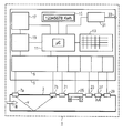
- the single figure shows an embodiment of a detection device, which as a flow meter 1 for a fluid is trained.
- fluid is in particular understood: a gas, a gas or a liquid fuel mixture or a liquid fuel.
- Gas mixtures are common also referred to as gas groups, but here in general referred to as gas.
- the flow meter 1 basically comprises a volume measuring device an ultrasonic measuring tube - hereinafter referred to as a measuring tube 3 denotes - and associated electronics 5.
- Das Measuring tube 3 works, for example, according to the generally known Ultrasonic transit time principle, starting from one ultrasound signal emitted by a first transducer 7a on a path V through the medium flowing in the measuring tube 3 or fluid and carried by a second transducer 7b Will be received. This process is done in opposite Repeated direction. Based on the runtime differences then the flow velocity of the fluid in the direction R is determined.
- the flow meter 1 can of course also be used a mechanical counter, e.g. with impeller his.
- Measuring tube distance and sound path is based on the known State of the art referenced.
- the input module 9 is on the output side with a central one Computing device 11 connected, in particular a microprocessor includes.
- a memory 13 a Display device, in particular a display 15, an operating module, in particular a keyboard 17 and a power supply module, in particular a power supply unit or a battery 19, assigned.
- Keyboard 17 and display 15 are used for operation and for information exchange.
- the battery 19 is used for Energy supply for the entire detection device.
- the memory 13 there are, among other things, conventional operating programs stored for the operation of the flow meter 1.
- the computing device 11 In of the computing device 11 are those of the input module 9 processed signals or values processed.
- the entire arrangement can be used as a detection device at least one physical property the following Sensors either directly on the measuring tube 3 or at least be arranged in the vicinity of the measuring tube 3 on the fluid flow must, alternatively or in any combination optional include:
- a temperature sensor 21, a pressure sensor 23, an infrared (IR) absorption measuring device 25, for example a Infrared light barrier includes, can be formed, a heatable resistor 27 or a sensor 29 for detection the conductivity or a dielectric constant of the Fluid.
- IR infrared
- sensors can either also work with the input module 9 or with separate input modules if necessary or Adaptation modules connected to the computer device 11 his. In the present case, all sensors are via a common input module 9 connected to the computer device 11.
- the modularity or separate processing of the measured values or signals is by the dashed division of the input module 9 indicated.
- the temperature sensor 21 and the pressure sensor 23 may be required if a heat count is carried out in the entire arrangement.
- the computer device can be used for further communication or for reading 11 via an interface module 31 with a Output 33 must be connected.
- the output 33 can be electrical Connection or formed as an optical interface be so that those generated by the computer device 11 or delivered values can be read out.
- Interface module 31 can also be used for input of information can be used in the computer device 11 his.
- the basic idea is that a change the type of fluid or, in the special case, the type of gas becomes. For this, at least a characteristic physical Monitored property of the fluid.
- the time of the change (relative or real time) is then possibly together with a cumulative value of the fluid volume stored in memory 13 as a pair of values.
- the border or the Limit band conditions can be changed in the memory 13 and can, if necessary, via the keyboard 17 or the Interface module 31 changed or specified externally become.
- This comparative process can also be a procedure include, for example, a discontinuity in the Measurement signal or the temporal change in the measurement signal of the IR absorption measuring device 25 is determined. Kick one Discontinuity or disproportionate change in the measurement signal or value, the time information or a time stamp stored in memory 13.
- the detection of the fluid type change based on different physical properties.
- the are arranged on the measuring tube 3, can be used as desired.
- a further or alternative embodiment provides accordingly before that with an ultrasonic measuring device the ultrasonic propagation speed is determined in the fluid.
- an ultrasonic measuring device the ultrasonic propagation speed is determined in the fluid.
- Sound propagation speed in the fluid are available.
- a flow meter based on Ultrasound can serve as a transmitter.
- Processing the measured values and recording the changes is carried out by means of a suitable program which is in the memory 13 is stored in connection with the computing device 11, the microprocessor, possibly also within an Asics, can be executed.
- the processing of the information and measured values generated in this way can be done on site by manual reading or by data transfer respectively.
- operating personnel by means of a reading device at the output 33 Data, especially the value pairs for a given one Period, take over and this for import into a central computer to hand over.
- a reading device at the output 33 Data especially the value pairs for a given one Period, take over and this for import into a central computer to hand over.
- the preferred area of application for the new detection device and the process is billing gas consumption for end customers, especially for households.
- Cheap is that there is no decentralized comparative values or information for the gases, gas mixtures or absolute relative Energy values must be saved.
- Locally arranged The customer's meter is preferably only a volume consumption and a change in the fluid is determined. The absolute The calculation is then carried out using centrally stored values at the clearing house.
- this method is applicable to all fluids, where in particular a fluid change in connection with a Volume measurement should be recorded. So this goes over the actual energy metering out.
- liquid fluids e.g. B. liquid Fuels, conceivable, but then if necessary the detection of the physical property with regard to the Flammability or explosion safety other boundary conditions must be observed.
- the preferred application is Measuring the consumption of gas mixtures.
Landscapes
- Physics & Mathematics (AREA)
- General Physics & Mathematics (AREA)
- Fluid Mechanics (AREA)
- Electromagnetism (AREA)
- Spectroscopy & Molecular Physics (AREA)
- Analytical Chemistry (AREA)
- Life Sciences & Earth Sciences (AREA)
- Chemical & Material Sciences (AREA)
- Health & Medical Sciences (AREA)
- Biochemistry (AREA)
- General Health & Medical Sciences (AREA)
- Immunology (AREA)
- Pathology (AREA)
- Investigating Or Analyzing Materials By The Use Of Ultrasonic Waves (AREA)
- Measuring Volume Flow (AREA)
- Investigating Or Analyzing Materials Using Thermal Means (AREA)
Abstract
Description
- auf Basis der von der Einrichtung gelieferten Messwerte zumindest eine physikalische Eigenschaft oder eine Kombination physikalischer Eigenschaften des Fluids zu einem ersten und einem zweiten Zeitpunkt ermittelt werden,
- diese Messwerte miteinander verglichen werden, und
- bei einer eine vorgegebene Grenze unter- oder überschreitenden Differenz zwischen den Messwerten eine Zeitinformation im Speicher gespeichert ist.
- an einem Messort wird zu einem ersten Zeitpunkt ein erster Messwert für zumindest eine physikalische Eigenschaft des Fluids ermittelt und gespeichert,
- zu einem zweiten Zeitpunkt wird für die physikalische Eigenschaft ein zweiter Wert ermittelt und gespeichert,
- die beiden Messwerte für die physikalische Eigenschaft werden miteinander verglichen,
- bei einer eine vorgegebene Grenze unter- oder überschreitenden Differenz zwischen den Messwerten wird eine Zeitinformation als Information für den Wechsel der Gasart gespeichert.
- Eine Wärmeleitfähigkeits-Messeinrichtung zur Erfassung der Wärmeleitfähigkeit des Fluids. Hierzu kann der heizbare Widerstand 27 dienen.
- Eine Messeinrichtung zur Erfassung der elektrischen Leitfähigkeit des Fluids. Hierzu kann der Sensor 29 dienen.
- Eine Dielektrizitätskonstanten-Messeinrichtung zur Erfassung der Dielektrizitätskonstanten des Fluids. Hierzu kann ebenfalls der Sensor 29 dienen
Claims (12)
- Erfassungseinrichtung für ein Fluid, insbesondere für Gas, mit einer Einrichtung zur Erfassung zumindest einer physikalischen Eigenschaft des Fluids und einer Recheneinrichtung mit Speicher, wobeiauf Basis der von der Einrichtung gelieferten Messwerte zumindest eine physikalische Eigenschaft oder eine Kombination physikalischer Eigenschaften des Fluids zu einem ersten und einem zweiten Zeitpunkt ermittelt werden,diese Messwerte miteinander verglichen werden, undbei einer eine vorgegebene Grenze unter- oder überschreitenden Differenz zwischen den Messwerten eine Zeitinformation im Speicher gespeichert ist.
- Erfassungseinrichtung nach Anspruch 1, wobei die Einrichtung eine IR-Absorbtionsmesseinrichtung umfasst und als zu vergleichende Messwerte Werte der Infrarotabsorbtionsbanden des Fluids dienen.
- Erfassungseinrichtung nach einem der Ansprüche 1 oder 2, wobei die Erfassungseinrichtung eine Ultraschallmesseinrichtung umfasst und als zu vergleichende Messwerte Werte der Ultraschallausbreitungsgeschwindigkeit im Fluid dienen.
- Erfassungseinrichtung nach einem der Ansprüche 1 bis 3, wobei die Erfassungseinrichtung eine Wärmeleitfähigkeits-Messeinrichtung umfasst und als zu vergleichende Messwerte Werte der Wärmeleitfähigkeit des Fluids dienen.
- Erfassungseinrichtung nach einem der Ansprüche 1 bis 4, wobei die Erfassungseinrichtung eine Dielektrizitätskonstanten-Messeinrichtung umfasst und als zu vergleichende Messwerte Werte der Dielektrizitätskonstanten des Fluids dienen.
- Erfassungseinrichtung nach einem der Ansprüche 1 bis 5, wobei die Erfassungseinrichtung eine Einrichtung zur Erfassung der elektrischen Leitfähigkeit umfasst und als zu vergleichende Messwerte Werte der elektrischen Leitfähigkeit des Fluids dienen.
- Erfassungseinrichtung nach einem der Ansprüche 1 bis 6, wobei eine Volumenmesseinrichtung vorgesehen ist und zusätzlich zur Zeitinformation ein Wert für ein kumuliertes Fluidvolumen gespeichert ist.
- Erfassungseinrichtung nach einem der Ansprüche 1 bis 7, wobei ein Display und/oder eine Schnittstelle vorgesehen ist/sind und zumindest die gespeicherten Werte für die Zeitinformation und das Fluidvolumen über das Display und/oder die Schnittstelle auslesbar und gegebenenfalls an eine Zentrale übertragbar sind.
- Verfahren zur Ermittlung des Wechsels einer Fluidart, insbesondere von Gas, mit folgenden Schritten:an einem Messort wird zu einem ersten Zeitpunkt ein erster Messwert für zumindest eine physikalische Eigenschaft des Fluids ermittelt und gespeichert,zu einem zweiten Zeitpunkt wird für die physikalische Eigenschaft ein zweiter Wert ermittelt und gespeichert,die beiden Messwerte für die physikalische Eigenschaft werden miteinander verglichen,bei einer eine vorgegebene Grenze unter- oder überschreitenden Differenz zwischen den Messwerten wird eine Zeitinformation als Information für den Wechsel der Gasart gespeichert.
- Verfahren nach Anspruch 9, wobei die Schritte zu weiteren Zeitpunkten fortlaufend wiederholt werden.
- Verfahren nach Anspruch 9 oder 10, wobei ein Wert für das den Messort zwischen den beiden Zeitpunkten passierende Fluidvolumen ermittelt und gespeichert wird.
- Verfahren nach Anspruch 11, wobei die Speicherung von Zeitinformation und Fluidvolumen in einem Gerät am ersten Messort erfolgt, diese Werte an einen zweiten Ort übertragen und dort der Brennwert für das Fluidvolumen ermittelt wird.
Applications Claiming Priority (2)
| Application Number | Priority Date | Filing Date | Title |
|---|---|---|---|
| DE10132477 | 2001-07-03 | ||
| DE10132477A DE10132477A1 (de) | 2001-07-03 | 2001-07-03 | Erfassungseinrichtung für ein Fluid und Verfahren zur Ermittlung des Wechsels einer Fluidart |
Publications (2)
| Publication Number | Publication Date |
|---|---|
| EP1273888A2 true EP1273888A2 (de) | 2003-01-08 |
| EP1273888A3 EP1273888A3 (de) | 2006-03-08 |
Family
ID=7690625
Family Applications (1)
| Application Number | Title | Priority Date | Filing Date |
|---|---|---|---|
| EP02013939A Withdrawn EP1273888A3 (de) | 2001-07-03 | 2002-06-24 | Erfassungseinrichtung für ein Fluid und Verfahren zur Ermittlung des Wechsels einer Fluidart |
Country Status (2)
| Country | Link |
|---|---|
| EP (1) | EP1273888A3 (de) |
| DE (1) | DE10132477A1 (de) |
Cited By (1)
| Publication number | Priority date | Publication date | Assignee | Title |
|---|---|---|---|---|
| WO2018185034A1 (fr) * | 2017-04-05 | 2018-10-11 | Sagemcom Energy & Telecom Sas | Compteur de fluide |
Families Citing this family (2)
| Publication number | Priority date | Publication date | Assignee | Title |
|---|---|---|---|---|
| DE102008063435A1 (de) * | 2008-12-31 | 2010-07-01 | Elster Meßtechnik GmbH | System und Verfahren zur Bestimmung und Überwachung von Volumenströmen |
| DE102014010189B4 (de) * | 2014-07-10 | 2019-03-28 | Diehl Metering Gmbh | Zählervorrichtung mit Rechenwerk und Volumengeber, Modul und Verfahren zum Betrieb einer Zählervorrichtung |
Family Cites Families (9)
| Publication number | Priority date | Publication date | Assignee | Title |
|---|---|---|---|---|
| LU76937A1 (de) * | 1977-03-11 | 1978-10-18 | ||
| DE3530669C2 (de) * | 1985-08-28 | 1987-02-26 | Heinz Walz Meß- und Regeltechnik, 8521 Effeltrich | Verfahren und Einrichtung zur Erfassung von Gasstoffwechselvorgängen bei intakten Pflanzen |
| CH679076A5 (de) * | 1989-06-13 | 1991-12-13 | Oscar Dr Sc Nat Oehler | |
| DE4337313C1 (de) * | 1993-11-02 | 1995-03-02 | Daimler Benz Ag | Vorrichtung zur Bestimmung eines Gasmassendurchsatzes einer Brennkraftmaschine |
| DE9411369U1 (de) * | 1994-07-05 | 1994-10-27 | Nöring, Eduard, Dipl.-Gartenb.-Ing., 15377 Buckow | Gerät zur Bestimmung des photosynthetischen Gaswechsels, Sauerstoff und Kohlendioxid, an pflanzlichen Materialien |
| DE19502078C2 (de) * | 1995-01-24 | 1996-04-18 | Walz Heinz Gmbh | Tragbare Gaswechselkammer |
| FR2776776B1 (fr) * | 1998-03-24 | 2000-04-28 | Schlumberger Ind Sa | Dispositif et procede de mesure directe de l'energie calorifique contenue dans un gaz combustible |
| DE19838301C2 (de) * | 1998-08-24 | 2001-03-01 | Fraunhofer Ges Forschung | Photometrische Vorrichtung und photometrisches Verfahren zum Ermitteln des Brennwertes eines Prüfgases |
| DE19921167A1 (de) * | 1999-02-24 | 2000-08-31 | Ruhrgas Ag | Verfahren und Anordnung zur Messung des Brennwertes und/oder des Wobbeindexes von Brenngas, insbesondere von Erdgas |
-
2001
- 2001-07-03 DE DE10132477A patent/DE10132477A1/de not_active Withdrawn
-
2002
- 2002-06-24 EP EP02013939A patent/EP1273888A3/de not_active Withdrawn
Cited By (2)
| Publication number | Priority date | Publication date | Assignee | Title |
|---|---|---|---|---|
| WO2018185034A1 (fr) * | 2017-04-05 | 2018-10-11 | Sagemcom Energy & Telecom Sas | Compteur de fluide |
| FR3065071A1 (fr) * | 2017-04-05 | 2018-10-12 | Sagemcom Energy & Telecom Sas | Compteur de fluide |
Also Published As
| Publication number | Publication date |
|---|---|
| EP1273888A3 (de) | 2006-03-08 |
| DE10132477A1 (de) | 2003-01-23 |
Similar Documents
| Publication | Publication Date | Title |
|---|---|---|
| EP1828670B1 (de) | Verfahren zur rechnergestützten bestimmung einer theoretisch verbleibenden lebensdauer einer austauschbaren batterie | |
| EP3084534B1 (de) | Feldgerät der prozessautomatisierung | |
| WO2008129050A1 (de) | Vorrichtung zur bestimmung und/oder überwachung des volumen- und/oder massedurchflusses eines mediums | |
| EP3569989B1 (de) | Fluidzähler | |
| DE102011003438A1 (de) | Einrichtung und Verfahren zur Ermittlung von Messwerten in einem strömenden Medium | |
| EP3855147B1 (de) | Energiezähler und verfahren zur erfassung einer wärme- oder kältemenge | |
| DE10132477A1 (de) | Erfassungseinrichtung für ein Fluid und Verfahren zur Ermittlung des Wechsels einer Fluidart | |
| DE102022102939A1 (de) | Durchflussmessgerät | |
| DE3010921A1 (de) | Durchflussmengenzaehler, insbesondere fuer die waermemengenmessung | |
| DE102004054118B4 (de) | Verfahren zum Betrieb eines Wärmezählers | |
| CN105090084A (zh) | 风机在线监测系统及其监测方法 | |
| DE102014009581A1 (de) | Ultraschall-Durchflussmessgerät und Verfahren zum Betreiben eines Ultraschall-Durchflussmessgerätes | |
| DE102010052104A1 (de) | Wärmezähler | |
| DE102014010189B4 (de) | Zählervorrichtung mit Rechenwerk und Volumengeber, Modul und Verfahren zum Betrieb einer Zählervorrichtung | |
| DE102006014678A1 (de) | Verfahren und Vorrichtung zur Bestimmung eines Wirkungsgrades | |
| DE10050262B4 (de) | Verfahren und Vorrichtung zur Bestimmung der Strömungsgeschwindigkeit, mit der ein Fluid in einer Hauptströmungsrichtung strömt | |
| CN218998210U (zh) | 一种具有数据实时传输功能的烟气流速监测器 | |
| DE102021203001B4 (de) | Verfahren zum Betrieb einer Heizkostenverteilervorrichtung und Heizkostenverteilervorrichtung | |
| DE102021203000B4 (de) | Verfahren zum Betrieb einer Heizkostenverteilervorrichtung und Heizkostenverteilervorrichtung | |
| DE19821536B4 (de) | Verfahren zum elektronischen Messen der von einem Heizkörper abgegebenen Wärmemenge | |
| DE102009031196A1 (de) | Anordnung zur Erfassung und Darstellung von Verbrauchsdaten eines Mediums | |
| DE19704492A1 (de) | Verfahren zum Erfassen und Verarbeiten von mittels Meßeinrichtungen, insbesondere Energiezählern gelieferten Meßdaten leitungsgebundender Medien und/oder Energien sowie System zur Durchführung des Verfahrens | |
| DE102005032132A1 (de) | Vorrichtung zur positionsabhängigen Detektion einer Leckage in einem verdeckten, von außen unzugänglichen Rohrleitungssystem | |
| CN207268637U (zh) | 一种液体流量计采集解码电路 | |
| EP3467441B1 (de) | Leistungserfassungsvorrichtung |
Legal Events
| Date | Code | Title | Description |
|---|---|---|---|
| PUAI | Public reference made under article 153(3) epc to a published international application that has entered the european phase |
Free format text: ORIGINAL CODE: 0009012 |
|
| AK | Designated contracting states |
Kind code of ref document: A2 Designated state(s): AT BE CH CY DE DK ES FI FR GB GR IE IT LI LU MC NL PT SE TR |
|
| AX | Request for extension of the european patent |
Free format text: AL;LT;LV;MK;RO;SI |
|
| RAP1 | Party data changed (applicant data changed or rights of an application transferred) |
Owner name: LANDIS+GYR GMBH |
|
| PUAL | Search report despatched |
Free format text: ORIGINAL CODE: 0009013 |
|
| AK | Designated contracting states |
Kind code of ref document: A3 Designated state(s): AT BE CH CY DE DK ES FI FR GB GR IE IT LI LU MC NL PT SE TR |
|
| AX | Request for extension of the european patent |
Extension state: AL LT LV MK RO SI |
|
| 17P | Request for examination filed |
Effective date: 20060817 |
|
| AKX | Designation fees paid |
Designated state(s): DE FR GB IT NL |
|
| 17Q | First examination report despatched |
Effective date: 20081216 |
|
| STAA | Information on the status of an ep patent application or granted ep patent |
Free format text: STATUS: THE APPLICATION IS DEEMED TO BE WITHDRAWN |
|
| 18D | Application deemed to be withdrawn |
Effective date: 20090428 |