EP1274231A2 - Méthode et dispositif pour contrôler les mouvements panoramiques et d'inclinaisons d'une caméra - Google Patents
Méthode et dispositif pour contrôler les mouvements panoramiques et d'inclinaisons d'une caméra Download PDFInfo
- Publication number
- EP1274231A2 EP1274231A2 EP02013214A EP02013214A EP1274231A2 EP 1274231 A2 EP1274231 A2 EP 1274231A2 EP 02013214 A EP02013214 A EP 02013214A EP 02013214 A EP02013214 A EP 02013214A EP 1274231 A2 EP1274231 A2 EP 1274231A2
- Authority
- EP
- European Patent Office
- Prior art keywords
- camera
- center
- angle
- target point
- visible image
- Prior art date
- Legal status (The legal status is an assumption and is not a legal conclusion. Google has not performed a legal analysis and makes no representation as to the accuracy of the status listed.)
- Granted
Links
Images


Classifications
-
- H—ELECTRICITY
- H04—ELECTRIC COMMUNICATION TECHNIQUE
- H04N—PICTORIAL COMMUNICATION, e.g. TELEVISION
- H04N23/00—Cameras or camera modules comprising electronic image sensors; Control thereof
- H04N23/60—Control of cameras or camera modules
- H04N23/695—Control of camera direction for changing a field of view, e.g. pan, tilt or based on tracking of objects
Definitions
- the invention relates to a method and a device for controlling Pan-tilt movements of a camera, especially a video camera in a surveillance system.
- the panning motion of the video surveillance camera becomes vertical extending axis, the so-called pan axis, and the tilting movement around the horizontal axis, the so-called tilt axis.
- the pan axis and the tilt axis are at an angle of 90 degrees to one another.
- a scene captured by a video surveillance camera will be on displayed on a video monitor or on the monitor of a PC.
- User-guided camera controls are in different Design forms known. Here, in particular, realizations with buttons for moving up, down, right and left as well as Combinations of these are used. The camera then pans the specified direction until the button is released, or in one another alternative embodiment is switched over until a corresponding one Stop button is pressed.
- the function of the keys is known from US 3984628 to be replaced by a joystick, by means of which the desired Direction of movement and the target can be approached.
- Embodiments are also known in which the monitor and the Operator function are coupled to a computer. In this case it will Digitized camera image and fed to the computer. The screen of the Computer or part of the screen then serves as a monitor for the camera. In this version, the previously mentioned buttons certain keys defined by the computer software or by the operator the computer keyboard.
- An image generated by the camera is sent to a first computer.
- the image is sent from the first computer to a first data connection sent another computer.
- the picture appears on the screen of the second Computers shown.
- the old position of the camera is one Assigned point on the screen of the second computer.
- On the The screen of the second computer is in addition to the image shown represented by the positioning device pointer.
- As answer to a signal that can be triggered with a trigger device becomes a new one Camera position depending on the current position of the pointer and the Center of the screen, which corresponds to the previous position of the camera assigned is calculated.
- the new position of the camera is from the second Computer via a second data connection to the first computer Posted.
- the new position of the camera is in the first computer Control information is converted and the camera is updated to the new one Move position.
- this does not take into account that the Angular position of the optical axis to the pan axis has an effect on whether the target point is set correctly. As a result, there is no geometry correction carried out.
- the object of the invention is to provide a method and a device, which disadvantages mentioned above, in particular the geometric distortion, avoids and an exact repositioning of the camera on a free selectable scene point enables.
- the method according to the solution is used for motor-driven swiveling and Tilting a video surveillance camera using a pan / tilt head, also called SNK or a so-called cathedral camera.
- the camera control consists of a control unit, which consists of a Computer unit, a display unit, an input unit and a transmitting / receiving unit composed.
- Security camera unit in a hierarchical structure Monitoring network available.
- the surveillance network exists, for example from a network of headquarters and sub-centers, an alarm system, a digitally based telephone network or Communication network.
- the communication network can be both analogue as well as a digital network.
- the surveillance camera unit consists of a surveillance camera, a positioning unit which positions the surveillance camera, in particular a pan-tilt head or dome, a control unit and a transmitting / receiving unit.
- the surveillance camera captures the scene it monitors.
- the video signals of the surveillance camera are transmitted from the control unit of the surveillance camera - preferably compressed - via the transmitting / receiving unit of the surveillance camera unit and via the surveillance network to the control unit of the camera control.
- the control unit of the camera control receives the transmitted video signal from the surveillance camera and forwards it to the computer unit. This decompresses the video signal, insofar as this is necessary, in particular if the video signal is transmitted in compressed form, and displays it on the display unit.
- the video signal data are transmitted in uncompressed form.
- a marker that shows the Represents the center of the display area of the display unit and at the same time the Center of the scene recorded by the surveillance camera unit designated.
- This Marking is assigned to one of the input units and is by means of this Input unit moved over the entire display area of the display unit.
- a user chooses a point in the from Surveillance camera captured scene by sending the marker to a moves any point of the display area of the display unit and by Activation of the input unit activated. This point is said to be due to the pan-tilt movement the surveillance camera in the middle of the display area the display unit can be moved.
- the computing unit calculates the relative distance between the mark on the display area of the Display unit and the center of the display area in horizontal and vertical direction with respect to the width and height of the display area of the Display unit and transmits this relative data via the transmitting / receiving unit to the control unit of the surveillance camera.
- this data is advantageously compressed before transmission.
- the control unit of the surveillance camera analyzes the transmitted ones Relative data and calculates the absolute values for controlling the Positioning unit of the surveillance camera. This is done using the current one Settings of the positioning unit of the surveillance camera in particular taking into account the lens opening angle. Then controls the Control unit of the surveillance camera, the positioning unit with the calculated absolute values. The surveillance camera will be as soon as possible aligned to the new position.
- the control commands can either be manual, as described in the previous, as also automatically, through image processing, so-called video motion detection, to be triggered.
- the location of the action is the Target point, determined on the monitor with an overlay mark by an analog-proportional operating means, e.g. B. a mouse, a Trackball, a touchscreen, etc. is moved.
- an analog-proportional operating means e.g. B. a mouse, a Trackball, a touchscreen, etc.
- By simple or Double click, short or long press or touch Commands are distinguished and triggered.
- cogs so-called Wheels and additional buttons can be used.
- the immunity of the system is particularly advantageous Transmission delays.
- the delay time has no influence on the Setting accuracy, because location information is always sent to the SNK or cathedral is transmitted and the transmission path is not in a man / machine control loop is involved.
- the transmission delay only causes that an action starts and ends with a delay. Since also only relative Transfer location information or data from the operator station to the SNK or Dom and the current, absolute position of Pan, Tilt, Focus and Zoom on Operator station is not required, the transmission system is unnecessary, relieves time-consuming data transfers.
- pan and tilt action the target point is in after a single click or similar shifted the center of the picture. For example, after double-clicking the Target point by pan and tilt action from one image edge to the other opposite picture edge or in the opposite picture corner postponed.
- the image section is displayed after a single click, or Similar, enlarged so that the target point is at the edge of the picture. This means, that the opening angle of the lens is reduced.
- the field of view is enlarged by a preselectable factor. This has the consequence that the opening angle of the lens is increased. Locally of the target point, the image is automatically focused by an auto focus function posed.
- the subsequent actions are performed.
- the Target point by constantly updating the displayed brand in the Center of the picture.
- the wheel also called wheel
- he can Opening angle of the lens can be enlarged and reduced, this means can be set to wide angle or telephoto.
- a focus point adjustment between close and far setting can be changed.
- the opening angle of the camera lens can be changed using the operating means.
- After pressing another shift key is the Readjustment of focus point.
- the different commands for pan and tilt or autofocus are always included the current, relative distances to the SNK or Dom. In particular, the relative center distances are transmitted.
- the relative center distances are transmitted.
- the number of Increments to be executed which are transferred by the manual movement to be triggered. After executing a command and reaching the Execution is reported back to the target setting. Is not an execution possible or if border conflicts arise, a corresponding one will take place Error message from the SNK or dome to the control unit
- a screen 1 is shown in FIG.
- the current scene recorded by a camera, in particular a video surveillance camera, is shown on this screen 1.
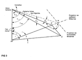
- the screen 1 has a virtual marking which marks the center M of the visible image. It also has a known width B of the visible image and a height H of the visible image.
- This target point Z is to be centered on the center M of the visible image by an action by SNK or Dom. For this, the distances between the target point Z and the center M of the visible image must first be calculated.
- the horizontal distance B Z is referred to as the distance between the target point Z and the center M of the visible image.
- the vertical distance H Z is determined as the distance between the target point Z and the center M of the visible image.
- the horizontal one must also be used Opening angle of the lens of the video surveillance camera and the vertical opening angle of the lens of the surveillance camera known his. This data is used for the further calculation to readjust the SNK or doms required.
- the horizontal opening angle ⁇ of the lens of the video surveillance camera for full image width B and the vertical opening angle ⁇ of the lens of the video surveillance camera for full image height H are known or can be measured by means of a position sensor of the zoom lens.
- the angle in the horizontal direction between the target point Z and the center M of the visible image hereinafter referred to as ⁇ Z
- ⁇ Z the angle in the vertical direction between the target point Z and the center M of the visible image
- the value ranges for the angles ⁇ Z and ⁇ Z extend in the range from> -90 ° to ⁇ + 90 °, since the values for the angles ⁇ and ⁇ for lenses used in security technology are between> 0 ° and ⁇ 180 ° and the values for the relative horizontal distance b Z and the relative vertical distance h Z are between 0 and + -1.
- the signs of b Z and h Z can therefore be transferred unchanged. Tangent values of infinity do not occur.
- the relative horizontal distance b Z and the relative vertical distance h Z or the horizontal angle ⁇ Z and the vertical angle ⁇ Z must be multiplied by -1 if the image on the screen is 1 180 ° is rotated around the center M of the screen 1.
- ⁇ Z is the tilt angle of point Z 'with respect to the pan axis before the tilt movement is carried out.
- the point Z ' is the horizontal projection of the target point Z onto the vertical central axis.
- the angle ⁇ M corresponds to the tilt angle of the center M of the visible image, or the optical axis of the lens, with respect to the pan axis before the tilt movement and is supplied by the position sensor of the SNK or dome.
- the tilt angle ⁇ ZM must be set by the pan-tilt movement of the SNK or dome.
- ⁇ ZM arccos (cos ⁇ Z * cos ⁇ Z )
- angle ⁇ Z can become purely arithmetically negative if the amount of - ⁇ Z is greater than ⁇ M.
- angle ⁇ ZM is less than 0, therefore has a negative sign, a correction must be made. Otherwise, objects which are recorded by the video surveillance camera would be displayed upside down on the screen 1.
- a solution alternative the sign of ⁇ ZM is inverted and the associated swivel angle ⁇ ZM is corrected by + -180 °.
- a second solution is to use the angles ⁇ ZM and ⁇ ZM as they were calculated. In this case, however, the video surveillance camera must be rotated +180 ° about the optical axis or the video signal must be post-processed so that the image on the screen 1 reappears in the normal position.
- ⁇ ' ZM is transferred to the SNK instead of the originally calculated ⁇ ZM .
- the swivel angle ⁇ has to be calculated and taken into account. The swivel angle ⁇ for the swivel movement to be carried out is calculated using the formula
- the swivel angle ⁇ is the angle through which the pan axis is swiveled must be to the target point Z in the center M of the visible image bring.
- ⁇ M is the angular position of the pan axis before the swivel movement
- ⁇ ZM is the angular position of the pan axis after the swivel movement.
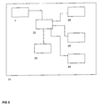
- the exemplary embodiment according to FIG. 4 is a Monitoring network, which consists of a central office 13, several Sub-centers 12, 14, 16, 18, a control unit 11 and the Surveillance camera units 15, 17 and 19 exist.
- control unit 11 shown in detail consists of the screen 1, a computing unit 22, operating units 23, 24, 25, which also Can be input devices such as a keyboard, mouse, etc., and a transmitting and receiving unit 26.
- the in FIG. 6 surveillance camera unit 17 shown in more detail consists of a camera unit 31, a positioning unit 34, a control unit 32 and a transmitting and receiving unit 33.
- the screen 1 is divided into several areas.
- the computing unit 22 controls the display on the screen 1. At least one display area is provided on the screen 1, in which the computing unit 22 displays the video signal of one of the surveillance camera units 15, 17 or 19, ie the scenes captured by them. In the further exemplary embodiment, however, only one video signal from a surveillance camera unit can be displayed on the entire screen 1. In an advantageous embodiment of the invention, however, there is the possibility of displaying several video signals from different surveillance cameras at the same time.
- Each of the existing surveillance camera units 15, 17, 19 can be selected and their current video signal can be displayed via each individual operating unit 23, 24, 25.
- the control units 23, 24, 25 are redundant.
- the surveillance camera unit 17 is selected and its video signal is displayed on the screen 1 of the control unit 11 by the computing unit 22 of the control unit 11.
- the camera unit 41 of the surveillance camera unit 17 captures a partial area of the field of view to be monitored.
- the control unit 42 of the surveillance camera unit 17 compresses the video signal of the camera unit 41 of the surveillance camera unit 17 and the transmitting and receiving unit 43 of the surveillance camera unit 17 transmits it to the sub-center 16.
- the latter transmits the compressed video signal to the center 13, which further transmits the compressed video signal to the control unit 11 transmitted.
- the control unit 11 receives the compressed video signal via the transmitting and receiving unit 26 and forwards it to the computing unit 22.
- the computing unit 22 decompresses the video signal and displays the video signal on the screen 1.
- To visualize the current settings of the surveillance camera unit 17 transmits the control unit 32 to the surveillance camera unit 17 any change in the setting of the positioning unit 34 of the Surveillance camera unit 17 and / or the zoom and / or the focus the camera unit 31 the surveillance camera unit 17 the current Setting data to the control unit 11.
- the computing unit 22 evaluates this Data and restores the current settings of the Surveillance camera unit 17 via scroll bars and markings in for is easily recognizable to the user.
- the user of the control unit 11 receives the scene currently recorded by the surveillance camera unit 17 on the screen 1. If the orientation of the surveillance camera unit 17 is to be changed, the operator controls, via the operating units 23, 24, 25, a marking at that point on the screen 1 which is to be the new center of the scene. This point is set as the target point Z by the control unit 11.
- the control unit 11 initiates the positioning of the surveillance camera unit 17 at the newly selected target point Z as the center of the scene, ie as the new center M of the visible image on the screen 1.
- the computing unit 22 calculates the distance between the target point Z and the center M of the visible image.
- the computing unit 22 determines the horizontal distance B Z as the horizontal distance between the target point Z and the center M of the visible image. In addition, the computing unit 22 determines the vertical distance H Z as the vertical distance between the target point Z and the center M of the visible image. If the target point Z is above the center M of the visible image, this is evaluated by the computing unit 22 with a positive sign. If it is below the center M of the visible image, the computing unit 22 assigns a negative sign. If the target point is to the left of the center M of the visible image, the horizontal distance B Z is evaluated by the computing unit 22 with a negative sign. If it is to the right of the center M of the visible image, the computing unit 22 evaluates this with a positive sign. In the specific exemplary embodiment according to FIG. 1, the target point Z lies on the right below the center M of the visible image. Therefore, the computing unit 22 assigns a positive sign for the horizontal distance B Z , but a negative sign for the vertical distance H Z.
- the relative horizontal distance b Z and the relative vertical distance h Z are calculated in relation to half the image width B and half the image height H. However, in a further embodiment of the invention there is the possibility of relating the relative distances to the full image width and height.
- the signs of the relative distances b Z and h Z are defined by the signs of the horizontal distances and vertical distances B Z and H Z.
- the computing unit 22 passes this relative distance data b Z and h Z via the control unit 11 to the center 13, from there via the sub-center 16 to the video surveillance camera unit 17.
- the transmitting and receiving unit of the surveillance camera unit 17 sets the values for the relative horizontal distance b Z and the relative vertical distance h Z in the memory.
- the control unit 32 knows the current horizontal opening angle ⁇ of the lens of the camera unit 31.
- the horizontal opening angle ⁇ of the lens is defined for the full image width B.
- the current opening angle ⁇ of the lens of the camera unit 31 for full image height H is also stored.
- the control unit 32 uses this data to calculate the horizontal angle ⁇ Z between the center M of the visible image and the target point Z.
- the control unit 32 calculates the angle ⁇ Z between the target point Z and the center M of the visible image using the formula:
- the signs for the angles ⁇ Z and ⁇ Z are determined by the signs of b Z and h Z.
- the value ranges for the angles ⁇ Z and ⁇ Z extend from> -90 ° to ⁇ + 90 °, since the values of the angles ⁇ and ⁇ for security technology lenses between> 0 ° and ⁇ 180 ° and the values for the relative vertical and horizontal distances b Z and h Z are in the range from 0 to + -1. Signs are therefore transmitted unchanged and tangent values against infinity do not occur.
- the control unit 32 To the surveillance camera unit 17 via the positioning unit 34 with the camera unit 31 fixed thereon towards the new target point Z. position, the control unit 32 must the inclination angle ⁇ Take into account the positioning unit 34 and the swivel angle ⁇ .
- the control unit 32 performs the calculation for the tilt angle ⁇ .
- the control unit has stored the inclination angle ⁇ M of the positioning unit 34. This is the angle between the optical axis and the pan axis, which is currently occupied by the positioning unit 34.
- the tilt angle ⁇ Z is the tilt angle of the target point Z 'with respect to the pan axis, before the tilting movement of the positioning unit 34 is carried out.
- the point Z' is the horizontal projection of the target point Z onto the vertical central axis.
- control unit 32 observes that the angle ⁇ Z can become purely arithmetically negative if the amount of - ⁇ Z is greater than ⁇ M. If the angle ⁇ Z is less than 0, the control unit 32 carries out a correction, since otherwise the scene which is recorded by the camera unit 31 would be displayed upside down on the screen 1. For this purpose, the control unit 32 inverts the sign of the angle ⁇ ZM and corrects the associated swivel angle ⁇ ZM by 180 °.
- angles ⁇ ZM and the swivel angle ⁇ ZM are used unchanged as they were calculated and the control unit 32 rotates the camera 180 ° around the optical axis.
- Control unit 11 or the computing unit 22 of the control unit 11 the wrong position of the picture and puts them on the screen 1 by electronic means normal position.
- the control unit 32 then moves the positioning unit 34 to the new tilt angle ⁇ ZM .
- the control unit 32 then calculates the swivel angle ⁇ , which must be carried out to finally the target point Z in the middle M of the visible image.
- the control unit 32 calculates the angle ⁇ for the swivel movement to be carried out as follows:
- the control unit 32 observes that the angle ⁇ Z does not assume the values 0 or 180 °. Otherwise there would be conflicts over division by 0. If the value of the angle ⁇ Z is 0 or 180 °, the control unit 32 uses a value for sin ⁇ Z which is somewhat greater than 0. The control unit preferably sets the sign of this value positively.
- ⁇ M is the absolute angle of the position encoder before the swivel movement and it is assumed that the value increases with clockwise rotation.
- the control unit 32 then controls the positioning unit 34 with the new value, whereupon the pan axis is set to the new angle ⁇ ZM .
- a new target point can be selected and the surveillance camera unit 17 can be set to this new target point. This is done in the manner described above.
- the screen 1 equipped with an image memory.
- the control unit 22 freezes after the Actuation of one of the operating units 23, 24, 25 the scene on the screen 1 on until the surveillance camera unit to the new setting values is set. Only then will the current scene appear on screen 1 again displayed.
- one of the operating units 23, 24, 25 is designed as a computer mouse.
- the zoom of the camera is controlled.
- the detail of the scene shown on the screen 1 indicated by the arrow head is moved to the edge of the picture.
- the larger value of b Z or h Z is transferred.
- this value is multiplied by the current opening angle of the camera lens and thus results in the new opening angle to be set.
- a factor that can be selected by default is transmitted.
- this factor is multiplied by the current opening angle of the camera lens and results in the new opening angle to be set.
- the monitoring time of the click duration can be selected by default settings.
Landscapes
- Engineering & Computer Science (AREA)
- Multimedia (AREA)
- Signal Processing (AREA)
- Studio Devices (AREA)
- Closed-Circuit Television Systems (AREA)
- Accessories Of Cameras (AREA)
- Casting Or Compression Moulding Of Plastics Or The Like (AREA)
Applications Claiming Priority (2)
| Application Number | Priority Date | Filing Date | Title |
|---|---|---|---|
| DE10132929 | 2001-07-06 | ||
| DE10132929A DE10132929B4 (de) | 2001-07-06 | 2001-07-06 | Verfahren und Vorrichtung zur Steuerung von Schwenk-Neige-Bewegungen einer Kamera |
Publications (3)
| Publication Number | Publication Date |
|---|---|
| EP1274231A2 true EP1274231A2 (fr) | 2003-01-08 |
| EP1274231A3 EP1274231A3 (fr) | 2004-06-30 |
| EP1274231B1 EP1274231B1 (fr) | 2009-04-08 |
Family
ID=7690922
Family Applications (1)
| Application Number | Title | Priority Date | Filing Date |
|---|---|---|---|
| EP02013214A Expired - Lifetime EP1274231B1 (fr) | 2001-07-06 | 2002-06-15 | Méthode et dispositif pour contrôler les mouvements panoramiques et d'inclinaisons d'une caméra |
Country Status (4)
| Country | Link |
|---|---|
| EP (1) | EP1274231B1 (fr) |
| AT (1) | ATE428268T1 (fr) |
| DE (2) | DE10132929B4 (fr) |
| ES (1) | ES2324523T3 (fr) |
Cited By (3)
| Publication number | Priority date | Publication date | Assignee | Title |
|---|---|---|---|---|
| EP1696383A3 (fr) * | 2005-02-25 | 2006-10-11 | Psion Teklogix Systems Inc. | Détection et correction automatiques de la distorsion de perspective pour l'imagerie documentaire |
| CN114598847A (zh) * | 2022-03-25 | 2022-06-07 | 中国民用航空总局第二研究所 | 用于视频监控的运动摄像机控制方法及装置 |
| EP4284012A1 (fr) * | 2022-05-24 | 2023-11-29 | IBAK Helmut Hunger GmbH & Co. KG | Procédé de commande d'une caméra d'un appareil d'inspection de canalisations |
Families Citing this family (1)
| Publication number | Priority date | Publication date | Assignee | Title |
|---|---|---|---|---|
| CO2017006569A1 (es) * | 2017-06-29 | 2019-01-18 | Institucion Univ Salazar Y Herrera | Sistema para monitoreo y asistencia de un usuario en espacios cerrados |
Family Cites Families (7)
| Publication number | Priority date | Publication date | Assignee | Title |
|---|---|---|---|---|
| US5164827A (en) * | 1991-08-22 | 1992-11-17 | Sensormatic Electronics Corporation | Surveillance system with master camera control of slave cameras |
| US5627616A (en) * | 1994-06-22 | 1997-05-06 | Philips Electronics North America Corporation | Surveillance camera system |
| US6768563B1 (en) * | 1995-02-24 | 2004-07-27 | Canon Kabushiki Kaisha | Image input system |
| DE19645981C2 (de) * | 1996-11-07 | 1999-07-01 | Ingbuero Fuer Elektro Mechanis | Vorrichtung zum Erzeugen kartennormierter Bilder |
| US5930740A (en) * | 1997-04-04 | 1999-07-27 | Evans & Sutherland Computer Corporation | Camera/lens calibration apparatus and method |
| US5990935A (en) * | 1997-04-04 | 1999-11-23 | Evans & Sutherland Computer Corporation | Method for measuring camera and lens properties for camera tracking |
| DE19811286C2 (de) * | 1998-03-16 | 2003-06-26 | Plettac Ag | Kamerabewegungssteuerung |
-
2001
- 2001-07-06 DE DE10132929A patent/DE10132929B4/de not_active Expired - Fee Related
-
2002
- 2002-06-15 AT AT02013214T patent/ATE428268T1/de not_active IP Right Cessation
- 2002-06-15 ES ES02013214T patent/ES2324523T3/es not_active Expired - Lifetime
- 2002-06-15 DE DE50213421T patent/DE50213421D1/de not_active Expired - Lifetime
- 2002-06-15 EP EP02013214A patent/EP1274231B1/fr not_active Expired - Lifetime
Cited By (3)
| Publication number | Priority date | Publication date | Assignee | Title |
|---|---|---|---|---|
| EP1696383A3 (fr) * | 2005-02-25 | 2006-10-11 | Psion Teklogix Systems Inc. | Détection et correction automatiques de la distorsion de perspective pour l'imagerie documentaire |
| CN114598847A (zh) * | 2022-03-25 | 2022-06-07 | 中国民用航空总局第二研究所 | 用于视频监控的运动摄像机控制方法及装置 |
| EP4284012A1 (fr) * | 2022-05-24 | 2023-11-29 | IBAK Helmut Hunger GmbH & Co. KG | Procédé de commande d'une caméra d'un appareil d'inspection de canalisations |
Also Published As
| Publication number | Publication date |
|---|---|
| ATE428268T1 (de) | 2009-04-15 |
| ES2324523T3 (es) | 2009-08-10 |
| EP1274231B1 (fr) | 2009-04-08 |
| DE50213421D1 (de) | 2009-05-20 |
| DE10132929B4 (de) | 2006-06-01 |
| EP1274231A3 (fr) | 2004-06-30 |
| DE10132929A1 (de) | 2003-01-23 |
Similar Documents
| Publication | Publication Date | Title |
|---|---|---|
| DE69429028T2 (de) | Rundumsicht Überwachungssystem mit bewegungsloser Kamera | |
| DE69520329T2 (de) | Kamerasteuervorrichtung und -Verfahren | |
| DE60031059T2 (de) | Videokamerabeobachtungssystem und Vorrichtung zur Anzeige von Bildern von dieser Videobeobachtungskamera | |
| DE69835185T2 (de) | Kamerasteuersystem | |
| DE69232663T2 (de) | Rundumsichtausrichtungssystem mit bewegungsloser kamera | |
| DE69216005T2 (de) | Fernseh-Überwachungsanlage, bei der Nebenkameras durch die Hauptkamera gesteuert werden | |
| EP1158271B1 (fr) | Procédé et dispositif pour la mise en oeuvre d'un flux de données et d'informations | |
| DE69233439T2 (de) | Überwachungsvorrichtung mit Steuerung der Kamera und der Linsenmontage | |
| DE112012005330B4 (de) | Verfahren und Vorrichtung zur Kompensation einer Überschreitung eines gewünschten Sichtbereichs durch eine ferngesteuerte Bilderfassungsvorrichtung | |
| DE69901958T2 (de) | Fokusanzeige für filmkamera mit hilfe der parallaxgeometrie von zwei videokameras | |
| DE102007001946A1 (de) | Terminalgerät, Verfahren und computerlesbares Aufnahmemedium | |
| DE19932217A1 (de) | Steuervorrichtung | |
| DE69000774T2 (de) | Verfahren und vorrichtung zur fernsteuerung einer fernsehkamera oder laufbildfilmkamera. | |
| DE112013000762T5 (de) | Bildverarbeitungsvorrichtung und Bildverarbeitungsverfahren | |
| EP3985964B1 (fr) | Dispositif de télécommande pour une caméra à image animée | |
| DE102007037310A1 (de) | Netzwerkkamera und Steuerungsverfahren hierfür | |
| DE602005000666T2 (de) | Kameraverbundsystem, Kameravorrichtung und Steuerverfahren für den Kameraverbund | |
| DE10012629B4 (de) | Ferngesteuertes Schwenkkopfsystem | |
| WO2007104367A1 (fr) | Système de vidéosurveillance | |
| DE69418111T2 (de) | Steuergerät und Steuerverfahren für Bildeingabevorrichtung | |
| DE4233137C1 (de) | Verfahren und Vorrichtung zur Steuerung einer Kamera | |
| DE10132929B4 (de) | Verfahren und Vorrichtung zur Steuerung von Schwenk-Neige-Bewegungen einer Kamera | |
| DE19811286C2 (de) | Kamerabewegungssteuerung | |
| EP2898666B1 (fr) | Dispositif client pour représenter des images d'une caméra pilotable, procédé, programme d'ordinateur ainsi que système de surveillance comprenant le dispositif client | |
| DE112021002080T5 (de) | Informationsverarbeitungsvorrichtung, informationsverarbeitungsverfahren und programm |
Legal Events
| Date | Code | Title | Description |
|---|---|---|---|
| PUAI | Public reference made under article 153(3) epc to a published international application that has entered the european phase |
Free format text: ORIGINAL CODE: 0009012 |
|
| AK | Designated contracting states |
Kind code of ref document: A2 Designated state(s): AT BE CH CY DE DK ES FI FR GB GR IE IT LI LU MC NL PT SE TR |
|
| AX | Request for extension of the european patent |
Free format text: AL;LT;LV;MK;RO;SI |
|
| PUAL | Search report despatched |
Free format text: ORIGINAL CODE: 0009013 |
|
| AK | Designated contracting states |
Kind code of ref document: A3 Designated state(s): AT BE CH CY DE DK ES FI FR GB GR IE IT LI LU MC NL PT SE TR |
|
| AX | Request for extension of the european patent |
Extension state: AL LT LV MK RO SI |
|
| 17P | Request for examination filed |
Effective date: 20040731 |
|
| AKX | Designation fees paid |
Designated state(s): AT BE CH CY DE DK ES FI FR GB GR IE IT LI LU MC NL PT SE TR |
|
| 17Q | First examination report despatched |
Effective date: 20050504 |
|
| 19U | Interruption of proceedings before grant |
Effective date: 20031113 |
|
| 19W | Proceedings resumed before grant after interruption of proceedings |
Effective date: 20060301 |
|
| RAP1 | Party data changed (applicant data changed or rights of an application transferred) |
Owner name: FUNKWERK PLETTAC ELECTRONIC GMBH |
|
| 17Q | First examination report despatched |
Effective date: 20050504 |
|
| GRAP | Despatch of communication of intention to grant a patent |
Free format text: ORIGINAL CODE: EPIDOSNIGR1 |
|
| GRAS | Grant fee paid |
Free format text: ORIGINAL CODE: EPIDOSNIGR3 |
|
| GRAA | (expected) grant |
Free format text: ORIGINAL CODE: 0009210 |
|
| AK | Designated contracting states |
Kind code of ref document: B1 Designated state(s): AT BE CH CY DE DK ES FI FR GB GR IE IT LI LU MC NL PT SE TR |
|
| REG | Reference to a national code |
Ref country code: GB Ref legal event code: FG4D Free format text: NOT ENGLISH |
|
| REG | Reference to a national code |
Ref country code: CH Ref legal event code: EP |
|
| REG | Reference to a national code |
Ref country code: IE Ref legal event code: FG4D |
|
| REF | Corresponds to: |
Ref document number: 50213421 Country of ref document: DE Date of ref document: 20090520 Kind code of ref document: P |
|
| REG | Reference to a national code |
Ref country code: ES Ref legal event code: FG2A Ref document number: 2324523 Country of ref document: ES Kind code of ref document: T3 |
|
| REG | Reference to a national code |
Ref country code: IE Ref legal event code: FD4D |
|
| PG25 | Lapsed in a contracting state [announced via postgrant information from national office to epo] |
Ref country code: FI Free format text: LAPSE BECAUSE OF FAILURE TO SUBMIT A TRANSLATION OF THE DESCRIPTION OR TO PAY THE FEE WITHIN THE PRESCRIBED TIME-LIMIT Effective date: 20090408 Ref country code: PT Free format text: LAPSE BECAUSE OF FAILURE TO SUBMIT A TRANSLATION OF THE DESCRIPTION OR TO PAY THE FEE WITHIN THE PRESCRIBED TIME-LIMIT Effective date: 20090908 |
|
| PG25 | Lapsed in a contracting state [announced via postgrant information from national office to epo] |
Ref country code: SE Free format text: LAPSE BECAUSE OF FAILURE TO SUBMIT A TRANSLATION OF THE DESCRIPTION OR TO PAY THE FEE WITHIN THE PRESCRIBED TIME-LIMIT Effective date: 20090708 |
|
| BERE | Be: lapsed |
Owner name: FUNKWERK PLETTAC ELECTRONIC G.M.B.H. Effective date: 20090630 |
|
| PG25 | Lapsed in a contracting state [announced via postgrant information from national office to epo] |
Ref country code: IE Free format text: LAPSE BECAUSE OF FAILURE TO SUBMIT A TRANSLATION OF THE DESCRIPTION OR TO PAY THE FEE WITHIN THE PRESCRIBED TIME-LIMIT Effective date: 20090408 Ref country code: DK Free format text: LAPSE BECAUSE OF FAILURE TO SUBMIT A TRANSLATION OF THE DESCRIPTION OR TO PAY THE FEE WITHIN THE PRESCRIBED TIME-LIMIT Effective date: 20090408 Ref country code: MC Free format text: LAPSE BECAUSE OF NON-PAYMENT OF DUE FEES Effective date: 20090630 |
|
| REG | Reference to a national code |
Ref country code: CH Ref legal event code: PL |
|
| PLBE | No opposition filed within time limit |
Free format text: ORIGINAL CODE: 0009261 |
|
| STAA | Information on the status of an ep patent application or granted ep patent |
Free format text: STATUS: NO OPPOSITION FILED WITHIN TIME LIMIT |
|
| 26N | No opposition filed |
Effective date: 20100111 |
|
| PG25 | Lapsed in a contracting state [announced via postgrant information from national office to epo] |
Ref country code: CH Free format text: LAPSE BECAUSE OF NON-PAYMENT OF DUE FEES Effective date: 20090630 Ref country code: LI Free format text: LAPSE BECAUSE OF NON-PAYMENT OF DUE FEES Effective date: 20090630 |
|
| PG25 | Lapsed in a contracting state [announced via postgrant information from national office to epo] |
Ref country code: BE Free format text: LAPSE BECAUSE OF NON-PAYMENT OF DUE FEES Effective date: 20090630 |
|
| PG25 | Lapsed in a contracting state [announced via postgrant information from national office to epo] |
Ref country code: AT Free format text: LAPSE BECAUSE OF NON-PAYMENT OF DUE FEES Effective date: 20090615 |
|
| PG25 | Lapsed in a contracting state [announced via postgrant information from national office to epo] |
Ref country code: GR Free format text: LAPSE BECAUSE OF FAILURE TO SUBMIT A TRANSLATION OF THE DESCRIPTION OR TO PAY THE FEE WITHIN THE PRESCRIBED TIME-LIMIT Effective date: 20090709 |
|
| PG25 | Lapsed in a contracting state [announced via postgrant information from national office to epo] |
Ref country code: LU Free format text: LAPSE BECAUSE OF NON-PAYMENT OF DUE FEES Effective date: 20090615 |
|
| PG25 | Lapsed in a contracting state [announced via postgrant information from national office to epo] |
Ref country code: TR Free format text: LAPSE BECAUSE OF FAILURE TO SUBMIT A TRANSLATION OF THE DESCRIPTION OR TO PAY THE FEE WITHIN THE PRESCRIBED TIME-LIMIT Effective date: 20090408 |
|
| PG25 | Lapsed in a contracting state [announced via postgrant information from national office to epo] |
Ref country code: CY Free format text: LAPSE BECAUSE OF FAILURE TO SUBMIT A TRANSLATION OF THE DESCRIPTION OR TO PAY THE FEE WITHIN THE PRESCRIBED TIME-LIMIT Effective date: 20090408 |
|
| PGFP | Annual fee paid to national office [announced via postgrant information from national office to epo] |
Ref country code: ES Payment date: 20120625 Year of fee payment: 11 |
|
| PGFP | Annual fee paid to national office [announced via postgrant information from national office to epo] |
Ref country code: FR Payment date: 20130715 Year of fee payment: 12 |
|
| REG | Reference to a national code |
Ref country code: FR Ref legal event code: ST Effective date: 20150227 |
|
| PG25 | Lapsed in a contracting state [announced via postgrant information from national office to epo] |
Ref country code: FR Free format text: LAPSE BECAUSE OF NON-PAYMENT OF DUE FEES Effective date: 20140630 |
|
| REG | Reference to a national code |
Ref country code: DE Ref legal event code: R082 Ref document number: 50213421 Country of ref document: DE Representative=s name: MARYNIOK GBR PATENT- UND RECHTSANWALTSSOZIETAE, DE Ref country code: DE Ref legal event code: R081 Ref document number: 50213421 Country of ref document: DE Owner name: FUNKWERK VIDEO SYSTEME GMBH, DE Free format text: FORMER OWNER: FUNKWERK PLETTAC ELECTRONIC GMBH, 90766 FUERTH, DE Ref country code: DE Ref legal event code: R082 Ref document number: 50213421 Country of ref document: DE Representative=s name: DIE PATENTERIE GBR, DE |
|
| REG | Reference to a national code |
Ref country code: DE Ref legal event code: R082 Ref document number: 50213421 Country of ref document: DE Representative=s name: DIE PATENTERIE GBR, DE |
|
| REG | Reference to a national code |
Ref country code: ES Ref legal event code: FD2A Effective date: 20150724 |
|
| PG25 | Lapsed in a contracting state [announced via postgrant information from national office to epo] |
Ref country code: ES Free format text: LAPSE BECAUSE OF NON-PAYMENT OF DUE FEES Effective date: 20140616 |
|
| PGFP | Annual fee paid to national office [announced via postgrant information from national office to epo] |
Ref country code: DE Payment date: 20170510 Year of fee payment: 16 Ref country code: GB Payment date: 20170626 Year of fee payment: 16 |
|
| PGFP | Annual fee paid to national office [announced via postgrant information from national office to epo] |
Ref country code: NL Payment date: 20170626 Year of fee payment: 16 |
|
| PGFP | Annual fee paid to national office [announced via postgrant information from national office to epo] |
Ref country code: IT Payment date: 20170630 Year of fee payment: 16 |
|
| REG | Reference to a national code |
Ref country code: DE Ref legal event code: R119 Ref document number: 50213421 Country of ref document: DE |
|
| REG | Reference to a national code |
Ref country code: NL Ref legal event code: MM Effective date: 20180701 |
|
| GBPC | Gb: european patent ceased through non-payment of renewal fee |
Effective date: 20180615 |
|
| PG25 | Lapsed in a contracting state [announced via postgrant information from national office to epo] |
Ref country code: NL Free format text: LAPSE BECAUSE OF NON-PAYMENT OF DUE FEES Effective date: 20180701 |
|
| PG25 | Lapsed in a contracting state [announced via postgrant information from national office to epo] |
Ref country code: DE Free format text: LAPSE BECAUSE OF NON-PAYMENT OF DUE FEES Effective date: 20190101 Ref country code: GB Free format text: LAPSE BECAUSE OF NON-PAYMENT OF DUE FEES Effective date: 20180615 Ref country code: IT Free format text: LAPSE BECAUSE OF NON-PAYMENT OF DUE FEES Effective date: 20180615 |