EP1274239A1 - Appareil video d'enregistrement/lecture et procede video d'enregistrement/lecture - Google Patents
Appareil video d'enregistrement/lecture et procede video d'enregistrement/lecture Download PDFInfo
- Publication number
- EP1274239A1 EP1274239A1 EP01904550A EP01904550A EP1274239A1 EP 1274239 A1 EP1274239 A1 EP 1274239A1 EP 01904550 A EP01904550 A EP 01904550A EP 01904550 A EP01904550 A EP 01904550A EP 1274239 A1 EP1274239 A1 EP 1274239A1
- Authority
- EP
- European Patent Office
- Prior art keywords
- data
- memory
- recording
- writing
- written
- Prior art date
- Legal status (The legal status is an assumption and is not a legal conclusion. Google has not performed a legal analysis and makes no representation as to the accuracy of the status listed.)
- Granted
Links
- 238000000034 method Methods 0.000 title claims description 12
- 230000015654 memory Effects 0.000 claims abstract description 196
- 238000012544 monitoring process Methods 0.000 description 12
- 230000006835 compression Effects 0.000 description 10
- 238000007906 compression Methods 0.000 description 10
- 238000010586 diagram Methods 0.000 description 2
- 238000013139 quantization Methods 0.000 description 1
- 230000005236 sound signal Effects 0.000 description 1
Images



Classifications
-
- G—PHYSICS
- G11—INFORMATION STORAGE
- G11B—INFORMATION STORAGE BASED ON RELATIVE MOVEMENT BETWEEN RECORD CARRIER AND TRANSDUCER
- G11B20/00—Signal processing not specific to the method of recording or reproducing; Circuits therefor
- G11B20/10—Digital recording or reproducing
- G11B20/12—Formatting, e.g. arrangement of data block or words on the record carriers
- G11B20/1201—Formatting, e.g. arrangement of data block or words on the record carriers on tapes
-
- G—PHYSICS
- G11—INFORMATION STORAGE
- G11B—INFORMATION STORAGE BASED ON RELATIVE MOVEMENT BETWEEN RECORD CARRIER AND TRANSDUCER
- G11B20/00—Signal processing not specific to the method of recording or reproducing; Circuits therefor
- G11B20/10—Digital recording or reproducing
-
- G—PHYSICS
- G11—INFORMATION STORAGE
- G11B—INFORMATION STORAGE BASED ON RELATIVE MOVEMENT BETWEEN RECORD CARRIER AND TRANSDUCER
- G11B15/00—Driving, starting or stopping record carriers of filamentary or web form; Driving both such record carriers and heads; Guiding such record carriers or containers therefor; Control thereof; Control of operating function
- G11B15/02—Control of operating function, e.g. switching from recording to reproducing
-
- G—PHYSICS
- G11—INFORMATION STORAGE
- G11B—INFORMATION STORAGE BASED ON RELATIVE MOVEMENT BETWEEN RECORD CARRIER AND TRANSDUCER
- G11B19/00—Driving, starting, stopping record carriers not specifically of filamentary or web form, or of supports therefor; Control thereof; Control of operating function ; Driving both disc and head
- G11B19/02—Control of operating function, e.g. switching from recording to reproducing
-
- H—ELECTRICITY
- H04—ELECTRIC COMMUNICATION TECHNIQUE
- H04N—PICTORIAL COMMUNICATION, e.g. TELEVISION
- H04N5/00—Details of television systems
- H04N5/76—Television signal recording
- H04N5/91—Television signal processing therefor
- H04N5/92—Transformation of the television signal for recording, e.g. modulation, frequency changing; Inverse transformation for playback
-
- H—ELECTRICITY
- H04—ELECTRIC COMMUNICATION TECHNIQUE
- H04N—PICTORIAL COMMUNICATION, e.g. TELEVISION
- H04N9/00—Details of colour television systems
- H04N9/79—Processing of colour television signals in connection with recording
- H04N9/80—Transformation of the television signal for recording, e.g. modulation, frequency changing; Inverse transformation for playback
- H04N9/804—Transformation of the television signal for recording, e.g. modulation, frequency changing; Inverse transformation for playback involving pulse code modulation of the colour picture signal components
- H04N9/8042—Transformation of the television signal for recording, e.g. modulation, frequency changing; Inverse transformation for playback involving pulse code modulation of the colour picture signal components involving data reduction
- H04N9/8047—Transformation of the television signal for recording, e.g. modulation, frequency changing; Inverse transformation for playback involving pulse code modulation of the colour picture signal components involving data reduction using transform coding
Definitions
- the present invention relates to a video recorder/reproducer such as a digital VTR and a video recording/reproducing method.
- a recording stop request when a recording stop request is generated during a recording operation, the recording operation may be immediately stopped.
- the analog VTR immediately stops the recording operation.
- An object of the present invention is to provide a video recorder/reproducer and a video recording/reproducing method, in which video data which have been stored in a memory until a recording stop request is generated can be recorded on a recording medium.
- Another object of the present invention is to provide a video recorder/reproducer and a video recording/reproducing method, in which in a case where a recording request is generated while video data which have been stored in a memory until a recording stop request is generated are read out of the memory after the recording stop request is issued, new video data can be prevented from being overwritten on video data which have not been read out yet in the memory (video data which have not been recorded yet on a recording medium).
- a first video recorder/reproducer In a video recorder/reproducer that writes input video data or its compressed data into a memory and reads out, when the data corresponding to a predetermined capacity are written into the memory, the data from the memory and records the data on a recording medium at the time of recording, a first video recorder/reproducer according to the present invention is characterized by comprising means for continuing, when a recording stop request is inputted during a recording operation, an operation for reading out the data from the memory and an operation for recording the data on the recording medium but stopping the writing of the data into the memory; and means for stopping the recording operation after the readout of the data finally written into the memory and the writing of the data into the recording medium are terminated.
- a second video recorder/reproducer In a video recorder/reproducer that writes input video data or its compressed data into a memory and reads out, when the data corresponding to a predetermined capacity are written into the memory, the data from the memory and records the data on a recording medium at the time of recording, a second video recorder/reproducer according to the present invention is characterized by comprising a circuit for continuing, when a recording stop request is inputted during a recording operation, an operation for reading out the data from the memory and an operation for recording the data on the recording medium but stopping the writing of the data into the memory; and a circuit for stopping the recording operation after the readout of the data finally written into the memory and the writing of the data into the recording medium are terminated.
- a first video recording/reproducing method is characterized by comprising the steps of continuing, when a recording stop request is inputted during a recording operation, an operation for reading out the data from the memory and an operation for recording the data on the recording medium but stopping the writing of the data into the memory; and stopping the recording operation after the readout of the data finally written into the memory and the writing of the data into the recording medium are terminated.
- a third video recorder/reproducer is characterized by comprising means for continuing, when a recording stop request is inputted during a recording operation, an operation for reading out the data from the memory and an operation for recording the data on the recording medium but stopping the writing of the data into the memory; means for designating, when a recording request is inputted before the readout of the data finally written into the memory and the writing of the data into the recording medium are terminated, the memory different from the memory from which the data are currently read out as a memory into which new data is to be first written, and then resuming the writing of the data into the designated memory; and means for stopping, when the recording request is not inputted before the readout of the data finally written into the memory and the
- a fourth video recorder/reproducer is characterized by comprising a circuit for continuing, when a recording stop request is inputted during a recording operation, an operation for reading out the data from the memory and an operation for recording the data on the recording medium but stopping the writing of the data into the memory; a circuit for designating, when a recording request is inputted before the readout of the data finally written into the memory and the writing of the data into the recording medium are terminated, the memory different from the memory from which the data are currently read out as a memory into which new data is to be first written, and then resuming the writing of the data into the designated memory; and a circuit for stopping, when the recording request is not inputted before the readout of the data finally
- a second video recording/reproducing method is characterized by comprising the steps of continuing, when a recording stop request is inputted during a recording operation, an operation for reading out the data from the memory and an operation for recording the data on the recording medium but stopping the writing of the data into the memory; designating, when a recording request is inputted before the readout of the data finally written into the memory and the writing of the data into the recording medium are terminated, the memory different from the memory from which the data are currently read out as a memory into which new data is to be first written, and then resuming the writing of the data into the designated memory; and stopping, when the recording request is not inputted before the readout of the data finally written into the memory and the writing of the data into the recording medium
- Fig. 1 illustrates the overall configuration of a monitoring system.
- the monitoring system comprises a video camera (hereinafter referred to as a monitoring camera) 101, a digital VTR 102 for compressing a video signal obtained by the monitoring camera 101 and recording the compressed video signal on a video tape, and a monitor 103 for displaying a video reproduced by the digital VTR 102.
- a monitoring camera hereinafter referred to as a monitoring camera
- a digital VTR 102 for compressing a video signal obtained by the monitoring camera 101 and recording the compressed video signal on a video tape
- a monitor 103 for displaying a video reproduced by the digital VTR 102.
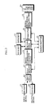
- Fig. 2 illustrates the configuration of the video signal processing circuit in the digital VRT 102. The operations at the time of recording of the video signal processing circuit will be described.
- an analog video signal fed from the monitoring camera 101 is converted into digital video data by a decoder 11.
- the video data obtained by the decoder 11 is fed to a first FPGA (Field Programmable Gate Array) 12.
- FPGA Field Programmable Gate Array
- the first FPGA 12 stores in a field memory 13 the inputted video data in a period of a predetermined number of fields (hereinafter referred to as an image acceptance period).
- the video data stored in the field memory 13 are fed to an image compression/expansion circuit 14, and are compressed for each field, for example, in a JPEG system by the image compression/expansion circuit 14.
- the compressed video data (coded data) obtained by the image compression/expansion circuit 14 is fed to a second FPGA 15.
- the second FPGA 15 adds additional information such as recording time information (information related to the current year, month, minute, and second), alarm information, and a camera number to the coded data fed from the image compression/expansion circuit 14.
- the alarm information is information generated on the basis of an alarm signal generated when it is detected that an important event is generated from the viewpoint of security.
- the monitoring camera 101 generates an alarm signal when a motion vector of an input video reaches not less than a predetermined value, and transmits the generated alarm signal to a microcomputer 22.
- the microcomputer 22 generates the alarm signal when an object sensing signal is inputted to the microcomputer 22 from an object sensor externally provided.
- the camera number is information for identifying, in such a system that videos from a plurality of monitoring cameras are inputted to the digital VTR 102 after being time-divided, information for identifying each of the monitoring cameras.
- the second FPGA 15 alternately writes the coded data to which the additional information is added into two memories 16 and 17 for each predetermined block including data corresponding to a plurality of fields, and reads out, every time the data corresponding to one block are written into the memory, the data from the memory into which the data corresponding to one block have been written, and feeds the read data to a formatter 18.
- One block is composed of data corresponding to 288 tracks, including information related to an audio in this example.
- the second FPGA 15 writes the coded data to which the additional information is added into one of the memories, for example, the first memory 16.
- the memory into which the data are to be written is switched to the other second memory 17 and at the same time, the readout of the data from the first memory 16 is started.
- the data read out of the first memory 16 is fed to the formatter 18. When the data corresponding to one block have been read out of the first memory 16, the readout is stopped.
- the memory into which the data are written is switched to the first memory 16 and at the same time, the readout of the data from the second memory 17 is started.
- the data read out of the second memory 17 is fed to the formatter 18.
- the readout is stopped. Thereafter, the same processing is repeated.
- the fed data is converted into data having a data structure which can be recorded on a video tape.
- the data obtained by the formatter 18 is recorded on a video tape (recording medium) 23 through a recording amplifier and a video head in the signal recording/reproduction unit 19. That is, the video data are basically recorded on the video tape 23 for each block (corresponding to 288 tracks). Every time the recording of the data for each block is terminated, the video tape is stopped.
- the second FPGA 15 and the formatter 18 are controlled by the microcomputer 22.
- Fig. 3 illustrates a format for data corresponding to one field recorded on a video tape.
- a data block corresponding to one field comprises a header 51, audio data 52, and video data 53.
- the header 51 includes additional information such as recording time information, alarm information, and a camera number, a quantization table (Q table), an audio added data, and so forth.
- a frame header (for example, "E1FFh") representing the head of the header 51 is inserted into the head of the header 51.
- An end code (EOI ; for example, "D9FFh) representing the end of the video data 53 is inserted into the end of the video data 53.
- a recording stop request is generated in cases where a recording stop button is pressed by a user, the recording end time has come at the time of timer recording, and alarm information is not inputted in alarm recording in which a video is recorded only when an alarm signal is inputted.
- Fig. 4 shows the operations of the microcomputer 22 in a case where the recording stop request is inputted during the recording operation.
- step 2 When the recording stop request is inputted during the recording operation (step 1), the writing of data into the memory 16 or 17 is stopped (step 2).
- the readout of the data from the memories 16 and 17 and the recording of the data on the recording medium 23 are continued (step 3).
- the readout of the data finally written out of the data stored in the memories 16 and 17 is terminated (YES at step 4)
- the readout of the data from the memories 16 and 17 is stopped (step 5).
- a recording request is generated in cases where a recording stop button is pressed by a user, the recording start time has come at the time of timer recording, and an alarm signal is inputted in alarm recording in which a video is recorded only when an alarm signal is inputted.
- Fig. 5 shows the operations of the microcomputer 22 in a case where a recording request is inputted when the readout of the data from one of the memories 16 and 17 is continued after a recording stop request is inputted.
- the memory different from the memory from which the data are currently read out out of the memories 16 and 17 is designated as a memory into which new data is first written (step 11).
- the memory designated at the step 11 is a memory in which the last data is written during the recording operation based on the previous recording request (step 12).
- the memory designated at the step 11 is a memory in which the last data is written during the recording operation based on the previous recording request (the memory from which the data are currently read out is not the memory in which the last data is written during the recording operation based on the previous recording request).
- out of addresses in the memory designated at the step 11 the address subsequent to the address in which the last data is written is set as a write start address, and the writing of the data into the memory designated at the step 11 is resumed (step 13).
- the head address in the memory designated at the step 11 is set as a write start address, and the writing of the data into the memory designated at the step 11 is then resumed (step 14).
- the readout of the data from the memory is stopped.
- the recording of the data read out of the memory is terminated, and dummy data corresponding to an amount of data which is shy of an amount of data corresponding to one block is recorded on the recording medium, the video tape is stopped once.
- the second memory 17 is designated as a memory in which new data is first written. Consequently, compressed data (coded data) of video data newly inputted is written into the second memory 17.
- the second memory is a memory in which the last data is written during the recording operation based on the previous recording request.
- the address subsequent to the address in which the last data is written is set as a write start address.
- the head address in the second memory is set as a write start address.
- the second FPGA 15 alternately writes the fed data (coded data and additional data) into the two memories 16 and 17 for each block, reads out, every time the data corresponding to one block are written into the memory, the data from the memory into which the data corresponding to one block have been written, and feeds the read data to the image compression/expansion circuit 14.
- Fig. 6 illustrates the data stored in each of the memories 16 and 17 by the second FPGA 15.
- the second FPGA 15 writes for each field the data fed from the formatter 18 into a main bank in each of the memories 16 and 17, and stores an address in which a frame header at the head of each of field data D 1 , D 2 , ⁇ D n for each field is stored (hereinafter referred to as a head storage address), which are written into the main bank, in a sub bank in the memory 16 or 17 in order that an address in which each of the field data D 1 , D 2 , ⁇ D n is written can be recognized.
- a head storage address an address in which a frame header at the head of each of field data D 1 , D 2 , ⁇ D n for each field is stored
- the microcomputer 22 successively designates addresses S 1 , S 2 , ⁇ , S n in this order in the sub-bank, so that the field data D 1 , D 2 , ⁇ D n are read out in this order, and coded video data in the read field data is fed to the image compression/expansion circuit 14.
- the microcomputer 22 designates the address S 1 in the sub-bank.
- the second FPGA 15 acquires the head storage address stored in the designated address S 1 , and reads out the field data D 1 from the acquired head storage address.
- additional information such as recording time information is separated from the field data D 1 .
- the separated additional information is fed to the microcomputer 22.
- audio data is separated from the field data D 1 .
- the separated audio data is fed to an audio signal processing circuit (not shown) .
- the coded video data in the field data D 1 is fed to the image compression/expansion circuit 14.
- the fed coded video data is expanded.
- the video data obtained by the image compression/expansion circuit 14 is stored in the field memory 13.
- the video data corresponding to one field are repeatedly read out by the first FPGA 12, and are fed to the encoder 21.
- the fed video data is returned to an analog video signal, and the analog video signal is fed to the monitor 103.
- the video data which have been stored in the memory until the recording stop request is generated can be recorded on the recording medium.
Landscapes
- Engineering & Computer Science (AREA)
- Signal Processing (AREA)
- Multimedia (AREA)
- Signal Processing For Digital Recording And Reproducing (AREA)
- Television Signal Processing For Recording (AREA)
- Closed-Circuit Television Systems (AREA)
Applications Claiming Priority (3)
| Application Number | Priority Date | Filing Date | Title |
|---|---|---|---|
| JP2000044066 | 2000-02-22 | ||
| JP2000044066A JP3548074B2 (ja) | 2000-02-22 | 2000-02-22 | 映像記録再生装置 |
| PCT/JP2001/001180 WO2001063918A1 (fr) | 2000-02-22 | 2001-02-19 | Appareil video d'enregistrement/lecture et procede video d'enregistrement/lecture |
Publications (3)
| Publication Number | Publication Date |
|---|---|
| EP1274239A1 true EP1274239A1 (fr) | 2003-01-08 |
| EP1274239A4 EP1274239A4 (fr) | 2004-10-20 |
| EP1274239B1 EP1274239B1 (fr) | 2007-01-10 |
Family
ID=18566890
Family Applications (1)
| Application Number | Title | Priority Date | Filing Date |
|---|---|---|---|
| EP01904550A Expired - Lifetime EP1274239B1 (fr) | 2000-02-22 | 2001-02-19 | Appareil video d'enregistrement/lecture et procede video d'enregistrement/lecture |
Country Status (7)
| Country | Link |
|---|---|
| US (1) | US7346262B2 (fr) |
| EP (1) | EP1274239B1 (fr) |
| JP (1) | JP3548074B2 (fr) |
| KR (1) | KR100758746B1 (fr) |
| CN (1) | CN1185871C (fr) |
| DE (1) | DE60125924T2 (fr) |
| WO (1) | WO2001063918A1 (fr) |
Families Citing this family (5)
| Publication number | Priority date | Publication date | Assignee | Title |
|---|---|---|---|---|
| US7580614B2 (en) * | 2002-12-09 | 2009-08-25 | Kabushiki Kaisha Toshiba | Information playback apparatus having expansion information storage unit and information playback method |
| US7636804B2 (en) * | 2003-04-28 | 2009-12-22 | Quantum Corporation | Data storage and protection apparatus and methods of data storage and protection |
| EP2733952A1 (fr) | 2005-10-21 | 2014-05-21 | Electronics and Telecommunications Research Institute | Dispositif et procédé de codage et de décodage d'une image mobile par balayage adaptatif |
| KR100882949B1 (ko) | 2006-08-17 | 2009-02-10 | 한국전자통신연구원 | 화소 유사성에 따라 적응적인 이산 코사인 변환 계수스캐닝을 이용한 부호화/복호화 장치 및 그 방법 |
| US8428305B2 (en) * | 2008-04-24 | 2013-04-23 | GM Global Technology Operations LLC | Method for detecting a clear path through topographical variation analysis |
Family Cites Families (11)
| Publication number | Priority date | Publication date | Assignee | Title |
|---|---|---|---|---|
| US5216552A (en) * | 1984-09-20 | 1993-06-01 | Go-Video, Inc. | Video cassette recorder having dual decks for selective simultaneous functions |
| JP2921879B2 (ja) * | 1989-09-29 | 1999-07-19 | 株式会社東芝 | 画像データ処理装置 |
| JPH06189317A (ja) * | 1991-08-28 | 1994-07-08 | Nikon Corp | 回転円盤方式tvカメラシステムを使用した静止画像観察装置 |
| EP0571221B1 (fr) * | 1992-05-22 | 1999-09-01 | Sony Corporation | Appareil d'enregistrement de disque et méthode d'enregistrement sur disque |
| JP3101435B2 (ja) * | 1992-08-31 | 2000-10-23 | キヤノン株式会社 | 電子カメラ |
| EP0585853B1 (fr) * | 1992-08-31 | 1999-05-19 | Canon Kabushiki Kaisha | Appareil de prise de vue |
| JP2928430B2 (ja) * | 1992-09-25 | 1999-08-03 | シャープ株式会社 | 記録再生装置 |
| JPH06253250A (ja) * | 1993-02-24 | 1994-09-09 | Matsushita Electric Ind Co Ltd | 映像メモリー装置 |
| US6169843B1 (en) * | 1995-12-01 | 2001-01-02 | Harmonic, Inc. | Recording and playback of audio-video transport streams |
| KR100491340B1 (ko) * | 1997-12-15 | 2005-05-24 | 마츠시타 덴끼 산교 가부시키가이샤 | 광디스크 재생장치 및 오디오 스트림을 재생하는 광디스크 재생방법 |
| JPH11313281A (ja) | 1998-04-30 | 1999-11-09 | Canon Inc | 撮像装置、画像データ記録方法及び記憶媒体 |
-
2000
- 2000-02-22 JP JP2000044066A patent/JP3548074B2/ja not_active Expired - Fee Related
-
2001
- 2001-02-19 DE DE60125924T patent/DE60125924T2/de not_active Expired - Lifetime
- 2001-02-19 KR KR1020027010907A patent/KR100758746B1/ko not_active Expired - Fee Related
- 2001-02-19 WO PCT/JP2001/001180 patent/WO2001063918A1/fr not_active Ceased
- 2001-02-19 EP EP01904550A patent/EP1274239B1/fr not_active Expired - Lifetime
- 2001-02-19 CN CNB018052924A patent/CN1185871C/zh not_active Expired - Fee Related
-
2002
- 2002-02-19 US US10/204,467 patent/US7346262B2/en not_active Expired - Fee Related
Non-Patent Citations (2)
| Title |
|---|
| No further relevant documents disclosed * |
| See also references of WO0163918A1 * |
Also Published As
| Publication number | Publication date |
|---|---|
| EP1274239B1 (fr) | 2007-01-10 |
| US7346262B2 (en) | 2008-03-18 |
| JP3548074B2 (ja) | 2004-07-28 |
| DE60125924T2 (de) | 2007-10-11 |
| JP2001236735A (ja) | 2001-08-31 |
| CN1185871C (zh) | 2005-01-19 |
| KR100758746B1 (ko) | 2007-09-14 |
| DE60125924D1 (de) | 2007-02-22 |
| WO2001063918A1 (fr) | 2001-08-30 |
| KR20020081342A (ko) | 2002-10-26 |
| CN1404689A (zh) | 2003-03-19 |
| EP1274239A4 (fr) | 2004-10-20 |
| US20030007779A1 (en) | 2003-01-09 |
Similar Documents
| Publication | Publication Date | Title |
|---|---|---|
| US7639920B2 (en) | Recorder | |
| US7346262B2 (en) | Video recorder/reproducer and video recording/reproducing method using a recording stop request | |
| JP3208360B2 (ja) | デジタルビデオレコーダ | |
| US7092613B1 (en) | Backup device in case of power failure in image recording apparatus | |
| JP3286615B2 (ja) | 映像記録装置、映像再生装置および映像記録再生装置 | |
| US6954582B2 (en) | Digital VTR and video recording / reproducing apparatus | |
| JP3747501B2 (ja) | ビデオデータ記録装置、および、その方法 | |
| JP3389526B2 (ja) | 録画装置 | |
| JP3416562B2 (ja) | 映像記録再生装置における特殊再生方法 | |
| JP2999990B2 (ja) | デジタルvtr | |
| US6768862B1 (en) | Retrieval method and retrieval device by designation of recording time in image recording/reproducing apparatus | |
| JP3548072B2 (ja) | 映像記録再生装置 | |
| US6766105B1 (en) | Digital VTR | |
| JP3548073B2 (ja) | 映像記録再生装置 | |
| EP1271946A1 (fr) | Enregistreur/lecteur video et procede d'enregistrement et de lecture video | |
| KR100328560B1 (ko) | 디지탈 비디오 레코더의 영상 기록/재생 시스템 | |
| JP3796180B2 (ja) | 映像記録再生用デジタル機器 | |
| KR0176171B1 (ko) | 감시용 디지탈 영상 시스템의 기록 및 재생 방법 | |
| JP3733039B2 (ja) | デジタルvtrにおける記録時刻指定による検索方法 | |
| JP3454772B2 (ja) | デジタルvtr | |
| JP3624443B2 (ja) | 記録装置 | |
| JPH06178249A (ja) | 映像記録再生装置 | |
| KR100626938B1 (ko) | 디브이알 시스템의 데이터 백업 방법 | |
| JPH09326991A (ja) | 画像記録方法及び装置 | |
| JP2000287229A (ja) | 映像記録再生装置におけるビデオヘッドの目詰まり検査方法および映像記録再生装置における記録方法 |
Legal Events
| Date | Code | Title | Description |
|---|---|---|---|
| PUAI | Public reference made under article 153(3) epc to a published international application that has entered the european phase |
Free format text: ORIGINAL CODE: 0009012 |
|
| 17P | Request for examination filed |
Effective date: 20020919 |
|
| AK | Designated contracting states |
Kind code of ref document: A1 Designated state(s): AT BE CH CY DE DK ES FI FR GB GR IE IT LI LU MC NL PT SE TR |
|
| AX | Request for extension of the european patent |
Free format text: AL;LT;LV;MK;RO;SI |
|
| RBV | Designated contracting states (corrected) |
Designated state(s): AT BE DE GB |
|
| A4 | Supplementary search report drawn up and despatched |
Effective date: 20040908 |
|
| RIC1 | Information provided on ipc code assigned before grant |
Ipc: 7H 04N 5/782 A Ipc: 7G 11B 20/10 B Ipc: 7G 11B 19/02 B Ipc: 7H 04N 5/91 B |
|
| 17Q | First examination report despatched |
Effective date: 20050323 |
|
| GRAP | Despatch of communication of intention to grant a patent |
Free format text: ORIGINAL CODE: EPIDOSNIGR1 |
|
| RIC1 | Information provided on ipc code assigned before grant |
Ipc: H04N 5/91 20060101ALI20060608BHEP Ipc: G11B 20/10 20060101ALI20060608BHEP Ipc: H04N 5/782 20060101AFI20060608BHEP |
|
| RBV | Designated contracting states (corrected) |
Designated state(s): DE GB |
|
| GRAS | Grant fee paid |
Free format text: ORIGINAL CODE: EPIDOSNIGR3 |
|
| GRAA | (expected) grant |
Free format text: ORIGINAL CODE: 0009210 |
|
| AK | Designated contracting states |
Kind code of ref document: B1 Designated state(s): DE GB |
|
| REG | Reference to a national code |
Ref country code: GB Ref legal event code: FG4D |
|
| REF | Corresponds to: |
Ref document number: 60125924 Country of ref document: DE Date of ref document: 20070222 Kind code of ref document: P |
|
| PLBE | No opposition filed within time limit |
Free format text: ORIGINAL CODE: 0009261 |
|
| STAA | Information on the status of an ep patent application or granted ep patent |
Free format text: STATUS: NO OPPOSITION FILED WITHIN TIME LIMIT |
|
| 26N | No opposition filed |
Effective date: 20071011 |
|
| PGFP | Annual fee paid to national office [announced via postgrant information from national office to epo] |
Ref country code: DE Payment date: 20130213 Year of fee payment: 13 Ref country code: GB Payment date: 20130213 Year of fee payment: 13 |
|
| REG | Reference to a national code |
Ref country code: DE Ref legal event code: R119 Ref document number: 60125924 Country of ref document: DE |
|
| GBPC | Gb: european patent ceased through non-payment of renewal fee |
Effective date: 20140219 |
|
| REG | Reference to a national code |
Ref country code: DE Ref legal event code: R119 Ref document number: 60125924 Country of ref document: DE Effective date: 20140902 |
|
| PG25 | Lapsed in a contracting state [announced via postgrant information from national office to epo] |
Ref country code: GB Free format text: LAPSE BECAUSE OF NON-PAYMENT OF DUE FEES Effective date: 20140219 Ref country code: DE Free format text: LAPSE BECAUSE OF NON-PAYMENT OF DUE FEES Effective date: 20140902 |