EP1274291A2 - Verfahren zur automatischen Projektierung der Steckplatzbelegung eines Racks einer speicherprogrammierbaren Steuerung - Google Patents
Verfahren zur automatischen Projektierung der Steckplatzbelegung eines Racks einer speicherprogrammierbaren Steuerung Download PDFInfo
- Publication number
- EP1274291A2 EP1274291A2 EP02014814A EP02014814A EP1274291A2 EP 1274291 A2 EP1274291 A2 EP 1274291A2 EP 02014814 A EP02014814 A EP 02014814A EP 02014814 A EP02014814 A EP 02014814A EP 1274291 A2 EP1274291 A2 EP 1274291A2
- Authority
- EP
- European Patent Office
- Prior art keywords
- modules
- rack
- programmable logic
- logic controller
- plc
- Prior art date
- Legal status (The legal status is an assumption and is not a legal conclusion. Google has not performed a legal analysis and makes no representation as to the accuracy of the status listed.)
- Ceased
Links
Images

Classifications
-
- G—PHYSICS
- G05—CONTROLLING; REGULATING
- G05B—CONTROL OR REGULATING SYSTEMS IN GENERAL; FUNCTIONAL ELEMENTS OF SUCH SYSTEMS; MONITORING OR TESTING ARRANGEMENTS FOR SUCH SYSTEMS OR ELEMENTS
- G05B19/00—Program-control systems
- G05B19/02—Program-control systems electric
-
- G—PHYSICS
- G06—COMPUTING OR CALCULATING; COUNTING
- G06F—ELECTRIC DIGITAL DATA PROCESSING
- G06F1/00—Details not covered by groups G06F3/00 - G06F13/00 and G06F21/00
- G06F1/16—Constructional details or arrangements
- G06F1/18—Packaging or power distribution
- G06F1/189—Power distribution
-
- G—PHYSICS
- G06—COMPUTING OR CALCULATING; COUNTING
- G06F—ELECTRIC DIGITAL DATA PROCESSING
- G06F1/00—Details not covered by groups G06F3/00 - G06F13/00 and G06F21/00
- G06F1/16—Constructional details or arrangements
- G06F1/20—Cooling means
-
- G—PHYSICS
- G06—COMPUTING OR CALCULATING; COUNTING
- G06F—ELECTRIC DIGITAL DATA PROCESSING
- G06F30/00—Computer-aided design [CAD]
Definitions
- the invention relates to a method for automatic project planning the slot assignment of a rack of a programmable logic controller Control (PLC) and a computer system with a software application installed on it for implementation of the procedure.
- PLC programmable logic controller Control
- Such programmable logic controllers are used in manufacturing technology to control a variety of processes common. According to the current state of the art programmable logic controllers on the individual modules arranged in a rack or put together to form an overall system.
- the arrangement of the individual modules is subject to this (Module types) certain rules. For example, it can be possible that one with a microprocessor Central unit (CPU module) only on a specific one Slot may be inserted.
- CPU module microprocessor Central unit
- the possibilities of arranging the modules e.g. Modules in Form of digital input / output modules or communication modules, held as freely as possible in the interests of the user.
- the individual module types of a PLC have different ones Values for current consumption and different power losses and thus a different self-heating.
- the modules are arranged in accordance with the prior art by the project engineer of the PLC. Thermal considerations are usually not considered for optimization. The Total power consumption is roughly calculated by the project engineer then the appropriate power supply selected. Depending on your expertise and experience of the project engineer at the PLC a more or less optimal arrangement of the modules especially from the point of view of optimal heat distribution within the PLC. Error in the arrangement of the modules can lead to the occurrence of unwanted local "hot spots" that reduce the service life of the modules.
- the object of the invention is achieved by the selection and the arrangement of the modules in the rack and / or the plugging together taking the modules into a complete system user and / or other definable Boundary conditions on the hardware and software side are such that a lowest achievable mean operating temperature of the programmable logic controller is realized, and / or that optimal heat distribution within the programmable Control is achieved, and / or that the Voltage drop on the back wall of the rack is minimized, and / or that a power loss and / or current balance is carried out.
- the advantage of this procedure is that the project engineer of the PLC supported in the selection and arrangement of the modules becomes. He can define certain boundary conditions, such as for example the use of a certain module or the arrangement of a particular module on a particular one Slot. In this way, errors in the module arrangement not from a thermal and other point of view occur more.
- the method is based on the selection of the power supply the result of power loss and electricity balancing. This has the advantage that the power supply is always optimal is dimensioned.
- Module temperatures in a PLC can range, for example between 20 ° C and 150 ° C.
- Procedures can be started, for example of module temperatures of 100 ° C (not optimized) operating temperatures of 50 ° C (optimized).
- Optimized operating temperatures achievable according to the method of the invention depend on the type of modules used, so that the temperature reduction achieved after optimization based on the non-optimized module arrangement for example ⁇ 50 ° C but can also be ⁇ 50 ° C. According to the invention it can also be ⁇ 40 ° C, ⁇ 30 ° C or ⁇ 20 ° C. If necessary, the temperature decrease after optimization are also well above 50 ° C.
Landscapes
- Engineering & Computer Science (AREA)
- Theoretical Computer Science (AREA)
- Physics & Mathematics (AREA)
- General Physics & Mathematics (AREA)
- General Engineering & Computer Science (AREA)
- Human Computer Interaction (AREA)
- Power Engineering (AREA)
- Computer Hardware Design (AREA)
- Evolutionary Computation (AREA)
- Geometry (AREA)
- Automation & Control Theory (AREA)
- Programmable Controllers (AREA)
Abstract
Description
- Module mit festen Steckplatzregeln werden auf den zwingend vorgesehenen Steckplätzen angeordnet;
- Module mit der höchsten Verlustleistung werden nach Möglichkeit mit Leerplätzen umgeben, ansonsten mit Modulen mit niedriger Verlustleistung;
- Module mit der höchsten Stromaufnahme werden möglichst
nah an der Stromversorgung angeordnet.
Das erfindungsgemäße Computersystem mit einer darauf installierten Softwareanwendung zur Durchführung des Verfahrens zeichnet sich dadurch aus, dass es mindestens eine Eingabeeinheit zur Eingabe der vom Benutzer oder andersseitig definierbarer Randbedingungen aufweist, dass es mindestens eine Rechnereinheit zur Berechnung der Betriebstemperatur, und/oder zur Durchführung einer Verlustleistungs- und/oder Strombilanzierung der speicherprogrammierbaren Steuerung aufweist, und dass es mindestens eine Speichereinheit zur Speicherung der Daten bezüglich Verlustleistung, Stromaufnahme und Steckplatzregeln der für die speicherprogrammierbare Steuerung in Betracht kommenden Module aufweist, auf die die Softwareanwendung zurückgreifen kann.
- Fig. 1
- eine Zusammenstellung der Module, aus denen eine SPS aufgebaut werden soll und
- Fig. 2
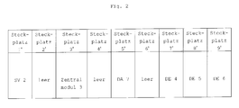
- die optimale Anordnung der Module nach Durchführung des erfindungsgemäßen Verfahrens.
Fig. 2 zeigt die optimale Anordnung der Module nach Durchführung des erfindungsgemäßen Verfahrens. Auf Steckplatz 1' wird die Stromversorgung SV 2 mit 5V/4A angeordnet, auf Steckplatz 3' der Mikroprozessor 3, auf Steckplatz 5' das Digitalausgabe-Modul 7, auf Steckplätzen 7', 8', 9' die Digitaleingabe-Module 4, 5, 6. Steckplätze 2', 4', 6' bleiben leer.
- Module mit festen Steckplatzregeln werden auf den zwingend vorgesehenen Steckplätzen angeordnet (hier SV 2 auf Steckplatz 1);
- Module mit der höchsten Verlustleistung werden nach Möglichkeit mit Leerplätzen umgeben, ansonsten mit Modulen mit niedriger Verlustleistung;
- Module mit der höchsten Stromaufnahme werden möglichst nah an der Stromversorgung angeordnet, um den Spannungsabfall zu minimieren.
Claims (4)
- Verfahren zur automatischen Projektierung der Steckplatzbelegung eines Racks einer speicherprogrammierbaren Steuerung (SPS), wobei Module in die Steckplätze des Racks steckbar sind, dadurch gekennzeichnet, dass eine Auswahl und eine Anordnung der Module im Rack und/oder das Zusammenstecken der Module zu einem Gesamtsystem unter Berücksichtigung vom Benutzer oder andersseitig definierbarer Randbedingungen hard- und softwareseitig derart erfolgt, dass eine niedrigste erreichbare mittlere Betriebstemperatur der SPS realisiert wird, und/oder dass eine optimale Wärmeverteilung innerhalb der SPS erreicht wird, und/oder dass der Spannungsabfall auf der Rückwand des Racks minimiert wird, und/oder dass eine Verlustleistungs- und/oder Strombilanzierung durchgeführt wird.
- Verfahren nach Anspruch 1, dadurch gekennzeichnet, dass die Auswahl der Stromversorgung auf dem Ergebnis der Verlustleistungs- und Strombilanzierung beruht.
- Verfahren nach Anspruch 1 oder Anspruch 2, dadurch gekennzeichnet, dass das Verfahren die nachfolgenden Schritte umfaßt:a. Module mit festen Steckplatzregeln werden auf den zwingend vorgesehenen Steckplätzen angeordnet;b. Module mit der höchsten Verlustleistung werden nach Möglichkeit mit Leerplätzen umgeben, ansonsten mit Modulen mit niedriger Verlustleistung;c. Module mit der höchsten Stromaufnahme werden möglichst nah an der Stromversorgung angeordnet.
- Computersystem mit einer darauf installierten Softwareanwendung zur Durchführung des Verfahrens nach einem der vorherstehenden Ansprüche, dadurch gekennzeichnet, dass es mindestens eine Eingabeeinheit zur Eingabe der vom Benutzer oder andersseitig definierbarer Randbedingungen aufweist, dass es mindestens eine Rechnereinheit zur Berechnung der Betriebstemperatur und/oder zur Durchführung einer Verlustleistungs- und/oder Strombilanzierung der speicherprogrammierbaren Steuerung aufweist, und dass es mindestens eine Speichereinheit zur Speicherung der Daten bezüglich Verlustleistung, Stromaufnahme und Steckplatzregeln der für die speicherprogrammierbare Steuerung in Betracht kommenden Module aufweist, auf die die Softwareanwendung zurückgreifen kann.
Applications Claiming Priority (2)
| Application Number | Priority Date | Filing Date | Title |
|---|---|---|---|
| DE10131943 | 2001-07-02 | ||
| DE10131943A DE10131943A1 (de) | 2001-07-02 | 2001-07-02 | Verfahren zur automatischen Projektierung der Steckplatzbelegung eines Racks einer speicherprogrammierbaren Steuerung |
Publications (2)
| Publication Number | Publication Date |
|---|---|
| EP1274291A2 true EP1274291A2 (de) | 2003-01-08 |
| EP1274291A3 EP1274291A3 (de) | 2007-10-31 |
Family
ID=7690280
Family Applications (1)
| Application Number | Title | Priority Date | Filing Date |
|---|---|---|---|
| EP02014814A Ceased EP1274291A3 (de) | 2001-07-02 | 2002-07-02 | Verfahren zur automatischen Projektierung der Steckplatzbelegung eines Racks einer speicherprogrammierbaren Steuerung |
Country Status (2)
| Country | Link |
|---|---|
| EP (1) | EP1274291A3 (de) |
| DE (1) | DE10131943A1 (de) |
Cited By (1)
| Publication number | Priority date | Publication date | Assignee | Title |
|---|---|---|---|---|
| EP1480092A3 (de) * | 2003-05-19 | 2007-01-10 | Siemens Aktiengesellschaft | Verfahren zur Projektierung eines Automatisierungssystems |
Families Citing this family (1)
| Publication number | Priority date | Publication date | Assignee | Title |
|---|---|---|---|---|
| DE10322273A1 (de) * | 2003-05-16 | 2004-12-02 | Siemens Ag | Projektierungsverfahren und Diagnoseverfahren für ein Automatisierungssystem |
Citations (1)
| Publication number | Priority date | Publication date | Assignee | Title |
|---|---|---|---|---|
| US5850539A (en) | 1995-05-23 | 1998-12-15 | Compaq Computer Corporation | Automated system for facilitating creation of a rack-mountable component personal computer |
Family Cites Families (2)
| Publication number | Priority date | Publication date | Assignee | Title |
|---|---|---|---|---|
| US6002854A (en) * | 1993-03-29 | 1999-12-14 | Trilogy Developmetn Group, Inc. | Method and apparatus for configuring systems |
| US5617514A (en) * | 1994-07-13 | 1997-04-01 | Unisys Corporation | Generalized configurator using multiple interacting packers and declaratively defined constraint expressions |
-
2001
- 2001-07-02 DE DE10131943A patent/DE10131943A1/de not_active Withdrawn
-
2002
- 2002-07-02 EP EP02014814A patent/EP1274291A3/de not_active Ceased
Patent Citations (1)
| Publication number | Priority date | Publication date | Assignee | Title |
|---|---|---|---|---|
| US5850539A (en) | 1995-05-23 | 1998-12-15 | Compaq Computer Corporation | Automated system for facilitating creation of a rack-mountable component personal computer |
Cited By (2)
| Publication number | Priority date | Publication date | Assignee | Title |
|---|---|---|---|---|
| EP1480092A3 (de) * | 2003-05-19 | 2007-01-10 | Siemens Aktiengesellschaft | Verfahren zur Projektierung eines Automatisierungssystems |
| US7508770B2 (en) | 2003-05-19 | 2009-03-24 | Siemens Aktiengesellschaft | Method for the project engineering of an automation system |
Also Published As
| Publication number | Publication date |
|---|---|
| DE10131943A1 (de) | 2003-01-16 |
| EP1274291A3 (de) | 2007-10-31 |
Similar Documents
| Publication | Publication Date | Title |
|---|---|---|
| EP2806319B1 (de) | Konfigurationssoftware und Verfahren zum Erstellen von Konfigurationsdaten und eines PLC-Programms für ein eine speicherprogrammierbare Steuerung umfassendes Steuer- und/oder Schutzgerät für die Mittel- oder Hochspannungstechnik | |
| EP1265333B1 (de) | Konfiguration eines Teils eines elektrischen Energieverteilnetzes | |
| EP2192457B1 (de) | Automatisierungskomponente für eine industrielle Automatisierungsanordnung und Verfahren zur Aktivierung eines Betriebszustandes | |
| EP0906596B1 (de) | Prozessautomatisierungssystem | |
| DE69636406T2 (de) | Spannungsregelmodul mit einer erweiterungsmöglichkeit | |
| DE19851131A1 (de) | Auf Herstellungsregeln basiertes, automatisiertes Entwurfs- und Herstellungssystem und -verfahren | |
| DE69802788T2 (de) | Ausrüstungszuweisungssystem | |
| EP1174781A2 (de) | Einrichtung zur Signalübertragung | |
| DE102014115678B4 (de) | Modulares Routersystem und Verfahren zur Veränderung einer hardwareseitigen Routerkonfiguration | |
| EP1184951B1 (de) | Verfahren und System zur Steuerung der Energieversorgung von elektrischen Verbrauchern | |
| DE19917102C2 (de) | Projektierungs- und Diagnoseeinrichtung für eine elektrische Anlage | |
| DE10131943A1 (de) | Verfahren zur automatischen Projektierung der Steckplatzbelegung eines Racks einer speicherprogrammierbaren Steuerung | |
| EP0939976B1 (de) | Einrichtung zur codierung von steckplätzen | |
| DE19932833A1 (de) | Verfahren zum Regeln der Gesamtleistung mindestens einer energietechnischen Anlage, umfassend eine Gruppe Verbraucher, insbesondere elektrischer Verbraucher | |
| DE19817191C2 (de) | Verfahren zum Regeln der Gesamtleistung von energietechnischen Anlagen, insbesondere einer Gruppe von elektrischen Verbrauchern | |
| WO2005096660A2 (de) | Elektrisches feldgerät | |
| DE102007050341A1 (de) | Induktionsmodul, Anordnung mehrerer Induktionsmodule und Verfahren zur Einrichtung eines solchen Induktionsmoduls | |
| EP3217509B1 (de) | Zwischenlager für batterieeinheiten | |
| DE102023001930A1 (de) | Planungsbüro-; projekt-; gewerke- und planungsphasenübergreifende nichttiefenmenügeführte nutzerfreundliche tabellenkalkulatorisch basierende technische Projekt-; Anlagen- sowie Anlagenkomponenteninformationsdatei mit normgerechtem nutzerfreundlichem nichttiefenmenügeführtem nahezu vollautomatisiertem Berechnungsaufsatz für Gebäudeautomation und Gebäudeleittechnik (Kostengruppe (KG)_480) | |
| EP0867793B1 (de) | Verfahren zur Steuerung von Arbeitsaufträgen in einem integrierten Produktionssystem | |
| EP2400360A1 (de) | Automatisierungsgerät und Verfahren zur Energieoptimierung | |
| EP0835596B1 (de) | Verfahren zum spezifizieren von multifunktionalen baugruppen in einem kommunikationssystem | |
| DE29701136U1 (de) | Busankoppler | |
| DE10324678B4 (de) | Dezentrales Antriebssystem | |
| DE10140748A1 (de) | Verfahren zur rechnerunterstützten Planung einer leittechnischen Anlage |
Legal Events
| Date | Code | Title | Description |
|---|---|---|---|
| PUAI | Public reference made under article 153(3) epc to a published international application that has entered the european phase |
Free format text: ORIGINAL CODE: 0009012 |
|
| AK | Designated contracting states |
Kind code of ref document: A2 Designated state(s): AT BE BG CH CY CZ DE DK EE ES FI FR GB GR IE IT LI LU MC NL PT SE SK TR |
|
| AX | Request for extension of the european patent |
Free format text: AL;LT;LV;MK;RO;SI |
|
| PUAL | Search report despatched |
Free format text: ORIGINAL CODE: 0009013 |
|
| AK | Designated contracting states |
Kind code of ref document: A3 Designated state(s): AT BE BG CH CY CZ DE DK EE ES FI FR GB GR IE IT LI LU MC NL PT SE SK TR |
|
| AX | Request for extension of the european patent |
Extension state: AL LT LV MK RO SI |
|
| RIC1 | Information provided on ipc code assigned before grant |
Ipc: G06F 17/50 20060101ALI20070926BHEP Ipc: H05K 7/20 20060101AFI20021029BHEP |
|
| 17P | Request for examination filed |
Effective date: 20080320 |
|
| AKX | Designation fees paid |
Designated state(s): AT BE BG CH CY CZ DE DK EE ES FI FR GB GR IE IT LI LU MC NL PT SE SK TR |
|
| 17Q | First examination report despatched |
Effective date: 20080729 |
|
| STAA | Information on the status of an ep patent application or granted ep patent |
Free format text: STATUS: THE APPLICATION HAS BEEN REFUSED |
|
| 18R | Application refused |
Effective date: 20091030 |