EP1274292A1 - Coffre pour convertisseur de puissance - Google Patents
Coffre pour convertisseur de puissance Download PDFInfo
- Publication number
- EP1274292A1 EP1274292A1 EP02291556A EP02291556A EP1274292A1 EP 1274292 A1 EP1274292 A1 EP 1274292A1 EP 02291556 A EP02291556 A EP 02291556A EP 02291556 A EP02291556 A EP 02291556A EP 1274292 A1 EP1274292 A1 EP 1274292A1
- Authority
- EP
- European Patent Office
- Prior art keywords
- power converter
- safe
- wall
- converter according
- power
- Prior art date
- Legal status (The legal status is an assumption and is not a legal conclusion. Google has not performed a legal analysis and makes no representation as to the accuracy of the status listed.)
- Granted
Links
- 238000001816 cooling Methods 0.000 claims abstract description 29
- 239000000758 substrate Substances 0.000 claims abstract description 7
- RYGMFSIKBFXOCR-UHFFFAOYSA-N Copper Chemical compound [Cu] RYGMFSIKBFXOCR-UHFFFAOYSA-N 0.000 claims description 11
- 229910052802 copper Inorganic materials 0.000 claims description 9
- 239000010949 copper Substances 0.000 claims description 9
- 239000006260 foam Substances 0.000 claims description 6
- 239000000463 material Substances 0.000 claims description 6
- 229910052782 aluminium Inorganic materials 0.000 claims description 5
- XAGFODPZIPBFFR-UHFFFAOYSA-N aluminium Chemical compound [Al] XAGFODPZIPBFFR-UHFFFAOYSA-N 0.000 claims description 5
- 239000011148 porous material Substances 0.000 claims description 5
- 239000002826 coolant Substances 0.000 claims description 4
- 230000000295 complement effect Effects 0.000 claims description 3
- 239000004065 semiconductor Substances 0.000 claims description 2
- 239000007788 liquid Substances 0.000 abstract description 6
- 241001441732 Ostraciidae Species 0.000 description 6
- 239000004020 conductor Substances 0.000 description 4
- 210000000038 chest Anatomy 0.000 description 3
- 206010001488 Aggression Diseases 0.000 description 2
- 230000016571 aggressive behavior Effects 0.000 description 2
- 239000003570 air Substances 0.000 description 2
- 238000010438 heat treatment Methods 0.000 description 2
- XLYOFNOQVPJJNP-UHFFFAOYSA-N water Substances O XLYOFNOQVPJJNP-UHFFFAOYSA-N 0.000 description 2
- 241000195940 Bryophyta Species 0.000 description 1
- YXLXNENXOJSQEI-UHFFFAOYSA-L Oxine-copper Chemical compound [Cu+2].C1=CN=C2C([O-])=CC=CC2=C1.C1=CN=C2C([O-])=CC=CC2=C1 YXLXNENXOJSQEI-UHFFFAOYSA-L 0.000 description 1
- XUIMIQQOPSSXEZ-UHFFFAOYSA-N Silicon Chemical compound [Si] XUIMIQQOPSSXEZ-UHFFFAOYSA-N 0.000 description 1
- 239000004411 aluminium Substances 0.000 description 1
- 239000012080 ambient air Substances 0.000 description 1
- 239000003990 capacitor Substances 0.000 description 1
- PMHQVHHXPFUNSP-UHFFFAOYSA-M copper(1+);methylsulfanylmethane;bromide Chemical compound Br[Cu].CSC PMHQVHHXPFUNSP-UHFFFAOYSA-M 0.000 description 1
- 230000001419 dependent effect Effects 0.000 description 1
- 230000000694 effects Effects 0.000 description 1
- 239000012777 electrically insulating material Substances 0.000 description 1
- 230000002708 enhancing effect Effects 0.000 description 1
- 238000001704 evaporation Methods 0.000 description 1
- 230000008020 evaporation Effects 0.000 description 1
- 238000002513 implantation Methods 0.000 description 1
- 238000009434 installation Methods 0.000 description 1
- 238000004519 manufacturing process Methods 0.000 description 1
- 239000007769 metal material Substances 0.000 description 1
- 230000004048 modification Effects 0.000 description 1
- 238000012986 modification Methods 0.000 description 1
- 235000011929 mousse Nutrition 0.000 description 1
- 239000003507 refrigerant Substances 0.000 description 1
- 229910052710 silicon Inorganic materials 0.000 description 1
- 239000010703 silicon Substances 0.000 description 1
- 229910000679 solder Inorganic materials 0.000 description 1
- 238000006467 substitution reaction Methods 0.000 description 1
- 238000003466 welding Methods 0.000 description 1
Images


Classifications
-
- H—ELECTRICITY
- H05—ELECTRIC TECHNIQUES NOT OTHERWISE PROVIDED FOR
- H05K—PRINTED CIRCUITS; CASINGS OR CONSTRUCTIONAL DETAILS OF ELECTRIC APPARATUS; MANUFACTURE OF ASSEMBLAGES OF ELECTRICAL COMPONENTS
- H05K7/00—Constructional details common to different types of electric apparatus
- H05K7/20—Modifications to facilitate cooling, ventilating, or heating
- H05K7/2089—Modifications to facilitate cooling, ventilating, or heating for power electronics, e.g. for inverters for controlling motor
- H05K7/20936—Liquid coolant with phase change
Definitions
- the invention relates to a trunk for a power converter for in particular to equip a traction chain of a railway vehicle.
- the maximum allowable current is dependent on the amount of heat that the device is able to evacuate.
- the most common solution used on railway vehicles to ensure the cooling of the power modules used in the converters consists of attach an aluminum radiator, equipped with cooling fins, against each different bases of power modules, all the different modules equipped with their cooling radiator being placed in a safe located under the vehicle and open on the sides to allow the circulation of a flow of air, especially when moving the vehicle.
- the purpose of the present invention is therefore to propose a box for modules power electronics which ensures, with great reliability, an excellent cooling power components in a small footprint, thus reducing the number of electronic power modules necessary for the realization of an installation of the inverter type in a chain of railway vehicle traction.
- the subject of the invention is a trunk for a power converter, intended in particular to equip a traction chain of a railway vehicle, comprising electronic power modules consisting of one or more power semiconductor components mounted on a substrate, characterized in that it comprises a base comprising a double-walled lower panel presenting an inner wall, disposed towards the inside of the trunk, on which is contiguous to the least one substrate supporting a power component, the lower panel extending by at least two double-walled side panels whose walls are cooled by means of cooling fins, and that both walls of the bottom panel delimit a hollow volume partially filled by a coolant and containing a permeable material, thermally conductive, realizing a thermal bridge between the two walls.
- FIG. 1 represents a box for a power converter intended to equip a traction chain of a subway.
- the trunk comprises a base 1 provided with a panel lower 3 double wall 3a and 3b extending by two side panels 2 extending perpendicular to the bottom panel 3.
- the two side panels 2 are also double-walled 2a and 2b and are symmetrical with respect to the plane longitudinal passing through the center of the trunk parallel to the side panels 2.
- the base 1 is preferably made of metal material good conductor heat.
- the lower panel 3 supports on its inner wall 3a, oriented towards the inside of the box, power modules 4 for the operation of the inverter, each power module consisting mainly of one or more components of type IGBT power mounted on conductive tracks made on a substrate 5 made of electrically insulating material and good conductor of heat, for example aluminum nitride AlN, the underside of the substrate 5 being contiguous directly to the inner wall 3a and being welded to the base 1 by means of a solder.
- a substrate 5 made of electrically insulating material and good conductor of heat, for example aluminum nitride AlN
- the side panels 2 support on their inner wall 2a components 6 which are preferably passive components, for example type capacitor, having the distinction of being less dissipative than the integrated power components in modules 4 arranged on the panel bottom 3 of the base 1.
- components 6 which are preferably passive components, for example type capacitor, having the distinction of being less dissipative than the integrated power components in modules 4 arranged on the panel bottom 3 of the base 1.
- each side panel 2 is accordion-shaped so as to forming multiple cooling fins, arranged perpendicular to the side panel 2, ensuring a heat exchange with the ambient air. These fins of cooling extend parallel to the axial direction of the subway so as to be swept by a stream of air when moving the subway.
- the box is closed by a lid 7 having a shape complementary to the base 1 and providing protection against the external aggressions of different 4.6 components located in the trunk.
- the lower panel 3 has a hollow volume disposed between the two walls 3a and 3b, which is filled with a permeable material 8, such as copper foam, providing strong conduction between the inner wall 3a and the outer wall 3b of the lower panel 3.
- the lower panel 3 also contains a coolant, such as water, which partially filled the pores of the copper foam 8, the liquid level being dashed line in FIG. 2.
- the permeable material 8 may also consist of a stack grids, for example copper or aluminum, providing the same function of thermal bridge between the inner wall 3a and the outer wall 3b.
- the base 1 thus formed constitutes a two-phase system in which the liquid contained in copper foam 8 evaporates through the pores during the rise of temperature caused by the operation of the various components of power, the vapor thus released traveling through the side panels 2 and condensing on the outer wall 2b, at the level of the cooling fins.
- the condensed and cooled liquid then falls back into the copper 8 panel foam lower 3 and contributes to the cooling of the power modules arranged on the inner wall 3a of the lower panel 3.
- the passive components, arranged on the side panels 2, are themselves cooled by conduction through the inner wall 2a of the side panels 2.
- FIGS. 3 and 4 show an alternative embodiment of the box according to the invention in which the lower panel 3 of the base has an outer wall 3b accordion forming multiple fins enhancing cooling efficiency.
- the side panels 2 of the base 1, the cover 7, the implantation of the different power modules 4 and passive components 6 remain unchanged by relative to the embodiment previously described.
- the lower panel 3 is hollow and is filled with a copper mouse 8 coming to fill the inside of the cooling fins as well as the space separating the inner wall 3a from the outer wall 3b in order to make a bridge thermal between the two walls 3a and 3b.
- the porous material 8 is partially filled with a liquid refrigerant such as water, the liquid level being shown in dotted line on the figure 4.
- Such a power converter box constitutes a two-phase system operating in a similar way to the box described in Figures 1 and 2, the cooling of power components being further enhanced by the surface more important exchange.
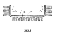
- FIG. 5 represents an alternative embodiment of the trunk of FIG. which the outer walls 2b and 3b of the side panels 2 and lower 3 are planes and the cooling fins are reported, for example by welding.
- the operation of such a trunk for power converter remains unchanged by compared to the box described in FIGS. 3 and 4.
- Such an embodiment variant presents the advantage of simplifying the manufacture of the safe.
- the chests for power converter according to the invention have the advantage to ensure excellent protection of the power modules against the aggressions thanks to the confinement of these in the trunk while ensuring a very efficient cooling.
- the cooling provided by such chests also remains effective when the vehicle is stopped by evaporation of the coolant in the bottom panel of the base.
Landscapes
- Engineering & Computer Science (AREA)
- Microelectronics & Electronic Packaging (AREA)
- Physics & Mathematics (AREA)
- Thermal Sciences (AREA)
- Cooling Or The Like Of Electrical Apparatus (AREA)
- Cooling Or The Like Of Semiconductors Or Solid State Devices (AREA)
- Electric Propulsion And Braking For Vehicles (AREA)
- Inverter Devices (AREA)
Abstract
Description
- le matériau perméable, thermiquement conducteur est un matériau poreux, tel qu'une mousse de cuivre, injecté dans le volume creux défini par les deux parois du panneau inférieur ;
- le matériau perméable, thermiquement conducteur, est constitué par un empilement de grilles en cuivre ou en aluminium entre les deux parois du panneau inférieur ;
- les panneaux latéraux comportent une paroi externe en accordéon définissant les ailettes de refroidissement ;
- les panneaux latéraux comportent une paroi externe plane sur laquelle sont rapportées les ailettes de refroidissement ;
- un ou plusieurs composants passifs sont accolés à la paroi interne des panneaux latéraux à double paroi ;
- un couvercle, de forme complémentaire au socle, vient fermer le coffre ;
- le panneau inférieur du socle comporte une paroi externe plane ;
- le panneau inférieur du socle comporte une paroi externe refroidie par des ailettes de refroidissement ;
- les composants de puissance sont des composants IGBT.
- la figure 1 est une vue en perspective d'un coffre pour modules électroniques de puissance selon un premier mode de réalisation de l'invention ;
- la figure 2 est une vue en coupe transversale du socle du coffre de la figure 1, représenté seul ;
- la figure 3 est une vue en perspective d'une variante de réalisation du coffre selon l'invention ;
- la figure 4 est en vue coupe en coupe transversale du socle du coffre de la figure 3, représenté seul ;
- la figure 5 est une vue en coupe transversale d'une autre variante de réalisation du coffre selon l'invention.
Claims (10)
- Coffre pour convertisseur de puissance, destiné notamment à équiper une chaíne de traction d'un véhicule ferroviaire, comprenant des modules électroniques de puissance (4) constitués d'un ou plusieurs composants semi-conducteurs de puissance montés sur un substrat (5), caractérisé en ce qu'il comprend un socle (1) comportant un panneau inférieur (3) à double parois (3a, 3b) présentant une paroi interne (3a), disposée vers l'intérieur du coffre, sur laquelle est accolée au moins un substrat (5) supportant un composant de puissance, ledit panneau inférieur (3) se prolongeant par au moins deux panneaux latéraux (2) à double parois (2a, 2b) dont les parois externes (2b) sont refroidies au moyen d'ailettes de refroidissement et en ce que les deux parois (3a, 3b) du panneau inférieur (3) délimitent un volume creux rempli partiellement par un liquide réfrigérant et contenant un matériau perméable thermiquement conducteur (8) réalisant un pont thermique entre les deux parois (3a, 3b).
- Coffre pour convertisseur de puissance selon la revendication 1, caractérisé en ce que ledit matériau perméable thermiquement conducteur (8) est un matériau poreux, tel qu'une mousse de cuivre, injecté dans ledit volume creux défini par les deux parois (3a, 3b).
- Coffre pour convertisseur de puissance selon la revendication 1, caractérisé en ce que ledit matériau perméable thermiquement conducteur (8) est constitué par un empilement de grilles en cuivre ou en aluminium entre les deux parois (3a, 3b).
- Coffre pour convertisseur de puissance selon l'une quelconque des revendications 1 à 3, lesdits panneaux latéraux (2) comportent une paroi externe (2b) en accordéon définissant lesdites ailettes de refroidissement.
- Coffre pour convertisseur de puissance selon l'une quelconque des revendications 1 à 3, caractérisé en ce que lesdits panneaux latéraux (2) comportent une paroi externe (2b) plane sur laquelle sont rapportées lesdites ailettes de refroidissement.
- Coffre pour convertisseur de puissance selon l'une quelconque des revendications 1 à 5, caractérisé en ce qu'un ou plusieurs composants passifs sont accolés à la paroi interne (2a) des panneaux latéraux (2) à double paroi.
- Coffre pour convertisseur de puissance selon l'une quelconque des revendications 1 à 6, caractérisé en ce qu'un couvercle (7), de forme complémentaire au socle (1), vient fermer ledit coffre.
- Coffre pour convertisseur de puissance selon l'une quelconque des revendications 1 à 7, caractérisé en ce que le panneau inférieur (3) du socle (1) comporte une paroi externe (3b) plane.
- Coffre pour convertisseur de puissance selon l'une quelconque des revendications 1 à 7, caractérisé en ce que le panneau inférieur (3) du socle (1) comporte une paroi externe (3b) refroidie par des ailettes de refroidissement.
- Coffre pour convertisseur de puissance selon l'une quelconque des revendications 1 à 9, caractérisé en ce que les composants de puissance sont des composants IGBT.
Applications Claiming Priority (2)
| Application Number | Priority Date | Filing Date | Title |
|---|---|---|---|
| FR0109007 | 2001-07-06 | ||
| FR0109007A FR2827115B1 (fr) | 2001-07-06 | 2001-07-06 | Coffre pour convertisseur de puissance |
Publications (2)
| Publication Number | Publication Date |
|---|---|
| EP1274292A1 true EP1274292A1 (fr) | 2003-01-08 |
| EP1274292B1 EP1274292B1 (fr) | 2008-04-23 |
Family
ID=8865212
Family Applications (1)
| Application Number | Title | Priority Date | Filing Date |
|---|---|---|---|
| EP02291556A Expired - Lifetime EP1274292B1 (fr) | 2001-07-06 | 2002-06-21 | Coffre pour convertisseur de puissance |
Country Status (7)
| Country | Link |
|---|---|
| US (1) | US6625024B2 (fr) |
| EP (1) | EP1274292B1 (fr) |
| JP (1) | JP2003115684A (fr) |
| CA (1) | CA2393069C (fr) |
| DE (1) | DE60226201T2 (fr) |
| ES (1) | ES2304421T3 (fr) |
| FR (1) | FR2827115B1 (fr) |
Cited By (2)
| Publication number | Priority date | Publication date | Assignee | Title |
|---|---|---|---|---|
| CN102461356A (zh) * | 2009-05-29 | 2012-05-16 | 标致·雪铁龙汽车公司 | 用于汽车的电力传送装置,以及设有这种装置的电力驱动或部分电力驱动的机动车 |
| EP3389087A1 (fr) * | 2017-04-13 | 2018-10-17 | Siemens Aktiengesellschaft | Module comprenant un semi-conducteur de puissance |
Families Citing this family (34)
| Publication number | Priority date | Publication date | Assignee | Title |
|---|---|---|---|---|
| US6808015B2 (en) * | 2000-03-24 | 2004-10-26 | Denso Corporation | Boiling cooler for cooling heating element by heat transfer with boiling |
| US6891725B2 (en) * | 2002-09-23 | 2005-05-10 | Siemens Energy & Automation, Inc. | System and method for improved motor controller |
| US6840311B2 (en) * | 2003-02-25 | 2005-01-11 | Delphi Technologies, Inc. | Compact thermosiphon for dissipating heat generated by electronic components |
| JP2004348650A (ja) * | 2003-05-26 | 2004-12-09 | Toshiba Corp | 電子機器 |
| TW577683U (en) * | 2003-06-02 | 2004-02-21 | Jiun-Guang Luo | Heat sink |
| JP2005107122A (ja) * | 2003-09-30 | 2005-04-21 | Toshiba Corp | 電子機器 |
| US6958910B2 (en) * | 2003-11-18 | 2005-10-25 | Kabushiki Kaisha Toshiba | Cooling apparatus for electronic apparatus |
| JP4387777B2 (ja) * | 2003-11-28 | 2009-12-24 | 株式会社東芝 | 電子機器 |
| JP2005190316A (ja) * | 2003-12-26 | 2005-07-14 | Toshiba Corp | 電子機器 |
| JP2005315157A (ja) * | 2004-04-28 | 2005-11-10 | Toshiba Corp | ポンプ、冷却装置および電子機器 |
| JP2005317798A (ja) * | 2004-04-28 | 2005-11-10 | Toshiba Corp | 電子機器 |
| JP2005315158A (ja) * | 2004-04-28 | 2005-11-10 | Toshiba Corp | ポンプ、冷却装置、および電子機器 |
| JP4234635B2 (ja) * | 2004-04-28 | 2009-03-04 | 株式会社東芝 | 電子機器 |
| JP2005315156A (ja) | 2004-04-28 | 2005-11-10 | Toshiba Corp | ポンプおよびポンプを備える電子機器 |
| JP2005317796A (ja) * | 2004-04-28 | 2005-11-10 | Toshiba Corp | ポンプ、冷却装置および電子機器 |
| JP2005315159A (ja) * | 2004-04-28 | 2005-11-10 | Toshiba Corp | ポンプ及び電子機器 |
| JP2005317797A (ja) * | 2004-04-28 | 2005-11-10 | Toshiba Corp | ポンプ、電子機器および冷却装置 |
| JP4343032B2 (ja) * | 2004-05-31 | 2009-10-14 | 株式会社東芝 | 冷却構造および投射型画像表示装置 |
| JP2005344562A (ja) * | 2004-06-01 | 2005-12-15 | Toshiba Corp | ポンプ、冷却装置および冷却装置を有する電子機器 |
| JP2006049382A (ja) * | 2004-07-30 | 2006-02-16 | Toshiba Corp | 冷却装置及び電子機器 |
| JP4844175B2 (ja) * | 2006-03-06 | 2011-12-28 | トヨタ自動車株式会社 | 筐体 |
| US8240359B2 (en) * | 2006-04-17 | 2012-08-14 | Gerald Garrett | Liquid storage and cooling computer case |
| JP2009124038A (ja) * | 2007-11-16 | 2009-06-04 | Toyo Electric Mfg Co Ltd | 屋根置型電気車制御装置用半導体冷却装置 |
| US8526179B2 (en) * | 2008-12-11 | 2013-09-03 | Hewlett-Packard Development Company, L.P. | Laptop computer user thermal isolation apparatus |
| US7929306B2 (en) * | 2009-03-31 | 2011-04-19 | Alcatel-Lucent Usa Inc. | Circuit pack cooling solution |
| DE202009015026U1 (de) * | 2009-11-04 | 2010-03-04 | Fischer Panda Gmbh | Vorrichtung zum Antrieb eines Fahrzeugs, insbesondere eines Wasserfahrzeugs |
| US8295049B2 (en) * | 2011-05-27 | 2012-10-23 | Renewable Power Conversion, Inc. | Power converter with linear distribution of heat sources |
| US9081554B2 (en) * | 2012-12-28 | 2015-07-14 | Intel Corporation | Heat exchanger assembly for electronic device |
| FR3010274B1 (fr) * | 2013-08-27 | 2016-10-21 | Valeo Equip Electr Moteur | Bloc convertisseur de puissance de vehicule electrique ou hybride |
| JP2015207586A (ja) * | 2014-04-17 | 2015-11-19 | 富士通株式会社 | 放熱装置、電子機器、基地局装置 |
| CN105934139B (zh) * | 2016-06-16 | 2018-05-22 | 广东合一新材料研究院有限公司 | 大功率器件的工质接触式冷却系统及其工作方法 |
| EP3796765A1 (fr) * | 2019-09-23 | 2021-03-24 | Wall Box Chargers S.L. | Système de conversion de puissance et chargeur de batterie à dissipation thermique améliorée |
| DE102022212458A1 (de) | 2022-11-22 | 2024-05-23 | Magna powertrain gmbh & co kg | Stromrichter mit direkt gekühltem Leistungsmodul und Verfahren zur Herstellung eines Stromrichters |
| EP4674721A1 (fr) * | 2024-07-05 | 2026-01-07 | ALSTOM Holdings | Dispositif de refroidissement pour refroidir une unité de puissance d'un véhicule ferroviaire, ensemble de refroidissement et véhicule ferroviaire associés |
Citations (4)
| Publication number | Priority date | Publication date | Assignee | Title |
|---|---|---|---|---|
| GB2076141A (en) * | 1980-05-13 | 1981-11-25 | Ericsson Telefon Ab L M | A Cooling Device for Discrete Electronic Components and/or Circuit Boards on which Components are Mounted |
| DE4307902C1 (de) * | 1993-03-12 | 1994-06-09 | Bosch Gmbh Robert | Kühlbare Einrichtung zur Aufnahme elektrischer Baugruppen |
| US5404272A (en) * | 1991-10-24 | 1995-04-04 | Transcal | Carrier for a card carrying electronic components and of low heat resistance |
| US6212074B1 (en) * | 2000-01-31 | 2001-04-03 | Sun Microsystems, Inc. | Apparatus for dissipating heat from a circuit board having a multilevel surface |
Family Cites Families (6)
| Publication number | Priority date | Publication date | Assignee | Title |
|---|---|---|---|---|
| US3741292A (en) * | 1971-06-30 | 1973-06-26 | Ibm | Liquid encapsulated air cooled module |
| EP0456508A3 (en) * | 1990-05-11 | 1993-01-20 | Fujitsu Limited | Immersion cooling coolant and electronic device using this coolant |
| US5390077A (en) * | 1994-07-14 | 1995-02-14 | At&T Global Information Solutions Company | Integrated circuit cooling device having internal baffle |
| US5969950A (en) * | 1998-11-04 | 1999-10-19 | Sun Microsystems, Inc. | Enhanced heat sink attachment |
| US6175501B1 (en) * | 1998-12-31 | 2001-01-16 | Lucent Technologies Inc. | Method and arrangement for cooling an electronic assembly |
| US6525420B2 (en) * | 2001-01-30 | 2003-02-25 | Thermal Corp. | Semiconductor package with lid heat spreader |
-
2001
- 2001-07-06 FR FR0109007A patent/FR2827115B1/fr not_active Expired - Fee Related
-
2002
- 2002-06-21 EP EP02291556A patent/EP1274292B1/fr not_active Expired - Lifetime
- 2002-06-21 ES ES02291556T patent/ES2304421T3/es not_active Expired - Lifetime
- 2002-06-21 DE DE60226201T patent/DE60226201T2/de not_active Expired - Lifetime
- 2002-07-03 JP JP2002194664A patent/JP2003115684A/ja active Pending
- 2002-07-03 US US10/188,089 patent/US6625024B2/en not_active Expired - Lifetime
- 2002-07-05 CA CA2393069A patent/CA2393069C/fr not_active Expired - Fee Related
Patent Citations (4)
| Publication number | Priority date | Publication date | Assignee | Title |
|---|---|---|---|---|
| GB2076141A (en) * | 1980-05-13 | 1981-11-25 | Ericsson Telefon Ab L M | A Cooling Device for Discrete Electronic Components and/or Circuit Boards on which Components are Mounted |
| US5404272A (en) * | 1991-10-24 | 1995-04-04 | Transcal | Carrier for a card carrying electronic components and of low heat resistance |
| DE4307902C1 (de) * | 1993-03-12 | 1994-06-09 | Bosch Gmbh Robert | Kühlbare Einrichtung zur Aufnahme elektrischer Baugruppen |
| US6212074B1 (en) * | 2000-01-31 | 2001-04-03 | Sun Microsystems, Inc. | Apparatus for dissipating heat from a circuit board having a multilevel surface |
Cited By (3)
| Publication number | Priority date | Publication date | Assignee | Title |
|---|---|---|---|---|
| CN102461356A (zh) * | 2009-05-29 | 2012-05-16 | 标致·雪铁龙汽车公司 | 用于汽车的电力传送装置,以及设有这种装置的电力驱动或部分电力驱动的机动车 |
| CN102461356B (zh) * | 2009-05-29 | 2014-12-24 | 标致·雪铁龙汽车公司 | 用于汽车的电力传送装置,以及设有这种装置的电力驱动或部分电力驱动的机动车 |
| EP3389087A1 (fr) * | 2017-04-13 | 2018-10-17 | Siemens Aktiengesellschaft | Module comprenant un semi-conducteur de puissance |
Also Published As
| Publication number | Publication date |
|---|---|
| JP2003115684A (ja) | 2003-04-18 |
| DE60226201T2 (de) | 2009-05-20 |
| FR2827115A1 (fr) | 2003-01-10 |
| US6625024B2 (en) | 2003-09-23 |
| CA2393069A1 (fr) | 2003-01-06 |
| DE60226201D1 (de) | 2008-06-05 |
| CA2393069C (fr) | 2013-04-23 |
| FR2827115B1 (fr) | 2003-09-05 |
| ES2304421T3 (es) | 2008-10-16 |
| US20030117824A1 (en) | 2003-06-26 |
| EP1274292B1 (fr) | 2008-04-23 |
Similar Documents
| Publication | Publication Date | Title |
|---|---|---|
| CA2393069C (fr) | Coffre pour convertisseur de puissance | |
| EP0603048B1 (fr) | Système de dissipation de l'énergie calorifique dégagée par un composant électronique et enceinte close utilisée dans un tel système | |
| EP1243169B1 (fr) | Module electronique a haut pouvoir de refroidissement | |
| EP0321899B1 (fr) | Procédé et dispositif de refroidissement d'un boîtier de circuit intégré | |
| CA2684373C (fr) | Module pour ensemble de stockage d'energie electrique | |
| EP0599678B1 (fr) | Dispositif de réchauffage de cartes électroniques | |
| EP3551501B1 (fr) | Dispositif de dissipation de chaleur d'une unite de controle multimedia | |
| FR2664033A1 (fr) | Echangeur de chaleur refroidi par air pour assemblages multi-puces. | |
| FR2913751A1 (fr) | Dispositif d'eclairage et/ou de signalisation pour vehicule automobile comprenant une paroi externe pourvue d'une zone d'eclairage thermique. | |
| FR3054298A1 (fr) | Projecteur de lumiere de vehicule | |
| FR2804767A1 (fr) | Structure de dissipateur thermique pour utilisation dans un ordinateur | |
| EP2936954B1 (fr) | Dispositif de ventilation pour installation de ventilation, chauffage et/ou climatisation | |
| EP2936955A1 (fr) | Dispositif de refroidissement pour carte de circuit imprime | |
| EP1259104B1 (fr) | Système convertisseur de puissance pour véhicule de traction ferroviare | |
| EP2339232A1 (fr) | Lampe pour projecteur et projecteur muni d'une telle lampe | |
| FR2956557A1 (fr) | Module electronique et ensemble electronique comportant un tel module | |
| FR3154350A1 (fr) | Dispositif de stockage d'énergie électrique à double contrôle thermique et véhicule associé. | |
| EP4324311A1 (fr) | Dispositif electronique modulaire a refroidissement optimise | |
| FR3007894A1 (fr) | Module solaire a regulation du niveau d'humidite simplifie | |
| FR3082051A1 (fr) | Boitier de module de calculateur pour vehicule automobile | |
| EP1401252B1 (fr) | Armoire climatisée pour équipements, notamment de téléphonie | |
| EP0541456B1 (fr) | Support de carte de composants électroniques à faible résistance thermique | |
| EP0021307A1 (fr) | Dispositif pour le transfert de chaleur entre au moins deux sources de chaleur de manière à les maintenir à des niveaux thermiques différents | |
| FR3059466B1 (fr) | Dispositif d'evacuation de chaleur | |
| FR3083036A1 (fr) | Dispositif de refroidissement d’un moteur electrique pour vehicule automobile |
Legal Events
| Date | Code | Title | Description |
|---|---|---|---|
| PUAI | Public reference made under article 153(3) epc to a published international application that has entered the european phase |
Free format text: ORIGINAL CODE: 0009012 |
|
| AK | Designated contracting states |
Kind code of ref document: A1 Designated state(s): AT BE CH CY DE DK ES FI FR GB GR IE IT LI LU MC NL PT SE TR |
|
| AX | Request for extension of the european patent |
Free format text: AL;LT;LV;MK;RO;SI |
|
| 17P | Request for examination filed |
Effective date: 20030708 |
|
| AKX | Designation fees paid |
Designated state(s): DE ES GB IT SE |
|
| RAP1 | Party data changed (applicant data changed or rights of an application transferred) |
Owner name: ALSTOM |
|
| GRAP | Despatch of communication of intention to grant a patent |
Free format text: ORIGINAL CODE: EPIDOSNIGR1 |
|
| GRAS | Grant fee paid |
Free format text: ORIGINAL CODE: EPIDOSNIGR3 |
|
| GRAA | (expected) grant |
Free format text: ORIGINAL CODE: 0009210 |
|
| AK | Designated contracting states |
Kind code of ref document: B1 Designated state(s): DE ES GB IT SE |
|
| REG | Reference to a national code |
Ref country code: GB Ref legal event code: FG4D Free format text: NOT ENGLISH |
|
| REF | Corresponds to: |
Ref document number: 60226201 Country of ref document: DE Date of ref document: 20080605 Kind code of ref document: P |
|
| REG | Reference to a national code |
Ref country code: SE Ref legal event code: TRGR |
|
| REG | Reference to a national code |
Ref country code: ES Ref legal event code: FG2A Ref document number: 2304421 Country of ref document: ES Kind code of ref document: T3 |
|
| PLBE | No opposition filed within time limit |
Free format text: ORIGINAL CODE: 0009261 |
|
| STAA | Information on the status of an ep patent application or granted ep patent |
Free format text: STATUS: NO OPPOSITION FILED WITHIN TIME LIMIT |
|
| 26N | No opposition filed |
Effective date: 20090126 |
|
| REG | Reference to a national code |
Ref country code: DE Ref legal event code: R082 Ref document number: 60226201 Country of ref document: DE Representative=s name: DR. RALF KOTITSCHKE, DE Ref country code: DE Ref legal event code: R082 Ref document number: 60226201 Country of ref document: DE Representative=s name: KOTITSCHKE & HEURUNG PARTNERSCHAFT MBB PATENT-, DE Ref country code: DE Ref legal event code: R082 Ref document number: 60226201 Country of ref document: DE Representative=s name: KOTITSCHKE & HEURUNG PARTNERSCHAFT MBB, DE |
|
| REG | Reference to a national code |
Ref country code: DE Ref legal event code: R082 Ref document number: 60226201 Country of ref document: DE Representative=s name: DR. RALF KOTITSCHKE, DE Ref country code: DE Ref legal event code: R082 Ref document number: 60226201 Country of ref document: DE Representative=s name: KOTITSCHKE & HEURUNG PARTNERSCHAFT MBB, DE Ref country code: DE Ref legal event code: R081 Ref document number: 60226201 Country of ref document: DE Owner name: ALSTOM TRANSPORT TECHNOLOGIES, FR Free format text: FORMER OWNER: ALSTOM, LEVALLOIS-PERRET, FR Ref country code: DE Ref legal event code: R082 Ref document number: 60226201 Country of ref document: DE Representative=s name: KOTITSCHKE & HEURUNG PARTNERSCHAFT MBB PATENT-, DE |
|
| REG | Reference to a national code |
Ref country code: GB Ref legal event code: 732E Free format text: REGISTERED BETWEEN 20151001 AND 20151007 |
|
| REG | Reference to a national code |
Ref country code: GB Ref legal event code: 732E Free format text: REGISTERED BETWEEN 20151119 AND 20151125 |
|
| REG | Reference to a national code |
Ref country code: DE Ref legal event code: R082 Ref document number: 60226201 Country of ref document: DE Representative=s name: DR. RALF KOTITSCHKE, DE Ref country code: DE Ref legal event code: R081 Ref document number: 60226201 Country of ref document: DE Owner name: ALSTOM TRANSPORT TECHNOLOGIES, FR Free format text: FORMER OWNER: ALSTOM TRANSPORT TECHNOLOGIES, LEVALLOIS-PERRET, FR |
|
| REG | Reference to a national code |
Ref country code: ES Ref legal event code: PC2A Owner name: ALSTOM TRANSPORT SA Effective date: 20170928 |
|
| PGFP | Annual fee paid to national office [announced via postgrant information from national office to epo] |
Ref country code: DE Payment date: 20190619 Year of fee payment: 18 Ref country code: IT Payment date: 20190624 Year of fee payment: 18 |
|
| PGFP | Annual fee paid to national office [announced via postgrant information from national office to epo] |
Ref country code: SE Payment date: 20190619 Year of fee payment: 18 |
|
| PGFP | Annual fee paid to national office [announced via postgrant information from national office to epo] |
Ref country code: GB Payment date: 20190619 Year of fee payment: 18 Ref country code: ES Payment date: 20190719 Year of fee payment: 18 |
|
| REG | Reference to a national code |
Ref country code: DE Ref legal event code: R119 Ref document number: 60226201 Country of ref document: DE |
|
| GBPC | Gb: european patent ceased through non-payment of renewal fee |
Effective date: 20200621 |
|
| PG25 | Lapsed in a contracting state [announced via postgrant information from national office to epo] |
Ref country code: GB Free format text: LAPSE BECAUSE OF NON-PAYMENT OF DUE FEES Effective date: 20200621 |
|
| PG25 | Lapsed in a contracting state [announced via postgrant information from national office to epo] |
Ref country code: DE Free format text: LAPSE BECAUSE OF NON-PAYMENT OF DUE FEES Effective date: 20210101 Ref country code: SE Free format text: LAPSE BECAUSE OF NON-PAYMENT OF DUE FEES Effective date: 20200622 |
|
| REG | Reference to a national code |
Ref country code: ES Ref legal event code: PC2A Owner name: ALSTOM TRANSPORT TECHNOLOGIES Effective date: 20210528 |
|
| REG | Reference to a national code |
Ref country code: SE Ref legal event code: EUG |
|
| PG25 | Lapsed in a contracting state [announced via postgrant information from national office to epo] |
Ref country code: IT Free format text: LAPSE BECAUSE OF NON-PAYMENT OF DUE FEES Effective date: 20200621 |
|
| REG | Reference to a national code |
Ref country code: ES Ref legal event code: FD2A Effective date: 20211103 |
|
| PG25 | Lapsed in a contracting state [announced via postgrant information from national office to epo] |
Ref country code: ES Free format text: LAPSE BECAUSE OF NON-PAYMENT OF DUE FEES Effective date: 20200622 |