EP1274334B1 - Haushaltsgerät - Google Patents
Haushaltsgerät Download PDFInfo
- Publication number
- EP1274334B1 EP1274334B1 EP01917021A EP01917021A EP1274334B1 EP 1274334 B1 EP1274334 B1 EP 1274334B1 EP 01917021 A EP01917021 A EP 01917021A EP 01917021 A EP01917021 A EP 01917021A EP 1274334 B1 EP1274334 B1 EP 1274334B1
- Authority
- EP
- European Patent Office
- Prior art keywords
- gear
- housing parts
- housing
- vibration
- domestic appliance
- Prior art date
- Legal status (The legal status is an assumption and is not a legal conclusion. Google has not performed a legal analysis and makes no representation as to the accuracy of the status listed.)
- Expired - Lifetime
Links
- 238000013016 damping Methods 0.000 claims abstract description 24
- 239000013536 elastomeric material Substances 0.000 claims description 3
- 239000012858 resilient material Substances 0.000 claims 1
- 125000006850 spacer group Chemical group 0.000 claims 1
- 230000005540 biological transmission Effects 0.000 description 9
- 239000013013 elastic material Substances 0.000 description 3
- 238000013459 approach Methods 0.000 description 2
- 229920001971 elastomer Polymers 0.000 description 1
- 239000000806 elastomer Substances 0.000 description 1
- 230000002349 favourable effect Effects 0.000 description 1
- 238000009434 installation Methods 0.000 description 1
- 238000009413 insulation Methods 0.000 description 1
- 238000004519 manufacturing process Methods 0.000 description 1
- 239000000463 material Substances 0.000 description 1
- 230000035939 shock Effects 0.000 description 1
Images


Classifications
-
- A—HUMAN NECESSITIES
- A47—FURNITURE; DOMESTIC ARTICLES OR APPLIANCES; COFFEE MILLS; SPICE MILLS; SUCTION CLEANERS IN GENERAL
- A47J—KITCHEN EQUIPMENT; COFFEE MILLS; SPICE MILLS; APPARATUS FOR MAKING BEVERAGES
- A47J43/00—Implements for preparing or holding food, not provided for in other groups of this subclass
- A47J43/04—Machines for domestic use not covered elsewhere, e.g. for grinding, mixing, stirring, kneading, emulsifying, whipping or beating foodstuffs, e.g. power-driven
- A47J43/07—Parts or details, e.g. mixing tools, whipping tools
- A47J43/08—Driving mechanisms
- A47J43/085—Driving mechanisms for machines with tools driven from the lower side
Definitions
- the invention relates to a household appliance according to the preamble of the independent claim 1.
- Such household appliance is known from DE-A-3045088.
- a planetary gear is arranged above a driven by a toothed belt from the drive motor of the machine gear.
- a planetary gear is arranged above a driven by a toothed belt from the drive motor of the machine gear.
- radially outwardly facing lugs are formed, which serve to fasten the fence to the housing of the machine.
- the invention has for its object to improve a household appliance according to the preamble of claim 1 with simple constructive measures such that a transmission of the noise emitted by a gear on the housing of the household appliance is at least largely prevented.
- vibration damping element By inserted at the attachment point or attachment points vibration damping element is carried out in a cost effective manner, a significant attenuation of the outgoing from the mounted gearbox and noise causing vibrations.
- a Geisseschdämmotherworm in the manufacturing process is easy to handle and with a few simple steps positionally correct attachable to the attachment points of the housing.
- the transmission has for its attachment support arms with receptacles on which the vibration-damping elements can be arranged as an intermediate layer between the housing parts used for fastening the transmission.
- the receptacles are designed as at least approximately vertically arranged retaining pin, to which a tube-like, vibration damping Element positively and / or non-positively attached, wherein the elements are adapted to the outer contour adapted receptacles on the housing parts.
- a retaining pin is provided on both sides on the support arms, onto which a tubular part consisting of elastomer material and serving as a vibration-damping element is plugged is that is inserted with its pipe jacket in arranged on both housing parts pipe sections.
- the receptacles are formed as at the support arms at least approximately vertically arranged pipe socket into which a tube-like designed vibration damping element form and / or non-positively inserted, wherein the elements are arranged with arranged on the housing parts retaining pin.
- a pipe socket is provided on both sides of the support arms, in which an existing elastomeric material, serving as a vibration damping element tube part is inserted, which is attachable with its tube opening in arranged on two housing parts retaining pin ,
- the pipe parts used in the pipe socket have a very soft characteristic due to their constructive shape, so that a particularly strong damping of the vibration emanating from the transmission takes place.
- the mounting of the support arms carrying the transmission with the housing parts is substantially improved and thus at the same time can be carried out with significantly reduced expenditure of time.
- a certain vibration damping is already achieved by the support arms.
- the pre-assembly of the support arms with the vibration damping elements is particularly simple and quick to carry out.
- the provided for holding the transmission support arms can contribute even to vibration damping, if according to another preferred embodiment of the subject invention, it is provided that the support arms are provided with a U-shaped bend. Due to the U-shaped bend the support arms already receive a certain elasticity, which has a favorable effect on the vibration damping.
- a particularly cost-effective and effective noise damping for a food processor with an electric drive to drive a planetary gear and a housing consisting of a housing top and a housing base, wherein the planetary gear has a fixed sprocket is achieved by the features of the independent expression 8.
- sprocket is also held by means of a patch, consisting of elastic material retaining ring in a formed on the upper part of the housing collar.
- the lower housing part of a food processor is called.
- a cup-shaped gear 2 is rotatably mounted.
- an external toothing 4 for a driven by the drive motor 5 of the food processor toothed belt 6 is present.
- the pot chamber 7 of the gear 2 of the fixed sprocket 8 of a planetary gear is arranged.
- the interior 9 of the ring gear 8 more about a molded in the middle of the pot bottom 10 of the gear 2 sun gear 11 driven planetary gears 12, of which only one is shown in FIG. 2, respectively.
- On the outside of the sprocket 8 three radially outwardly projecting support arms 13 are integrally formed with uniform circumferential spacing.
- the support arms 13 have a U-shaped bend 14, with which they overlap the pot shell 3 of the gear 2.
- sleeve-shaped fastening elements 15 which have an intermediate bottom 16 inside.
- the sleeve-shaped fastening elements 15 thus form two opposing receptacles 17, in the form of a pipe socket, in each of which an existing of elastic material pipe member 18 is inserted.
- the tube part 18 inserted in the receptacle 17 directed towards the lower housing part 1 is plugged with its tube opening 19 onto a pin 20 integrally formed on the lower housing part 1.
- the ring gear 8 is held on the lower housing part 1.
- the elastic tube member 18 a contact of rigid parts of the support arms 13, thus thus the ring gear 8, with rigid parts of the housing 1, ie the pin 20, avoided.
- this decoupling of rigid parts results from the elastic tube member 18 excellent noise attenuation.
- the upper housing part 21 of the food processor is inserted with integrally formed on it retaining pin 22 in the tube opening 19 of the inserted into the overhead receptacle 17 tube member 18.
- the upper housing part 21 is vibrationally decoupled from the sprocket 8, so that even on the upper housing part 21 noise can be transmitted only in highly damped form.
- the pipe parts 18 have a particularly soft characteristic due to their geometric shape, resulting in a particularly good noise attenuation.
- an existing elastic material retaining ring 23 is also plugged.
- the retaining ring 23 engages with an attached upper housing part 21 in an annular collar 14 provided on this. Hler notebook results in a further elastic support and in particular a good centering of the ring gear 8.
- the ring gear 8 is thus decoupled from both the lower and the upper housing part 1 and 21 vibration elastic.
Landscapes
- Engineering & Computer Science (AREA)
- Mechanical Engineering (AREA)
- Food Science & Technology (AREA)
- Vibration Prevention Devices (AREA)
- Retarders (AREA)
- Food-Manufacturing Devices (AREA)
- Gears, Cams (AREA)
- Filters For Electric Vacuum Cleaners (AREA)
Description
- Die Erfindung betrifft ein Haushaltsgerät mit nach dem Oberbegriff des unabhängigen Anspruchs 1.
- Solches Haushaltsgerät ist aus DE-A-3045088 bekannt.
- Bei einer auf dem Markt befindlichen Küchenmaschine (Siemens Küchenmaschine MK3) ist oberhalb eines über einen Zahnriemen vom Antriebsmotor der Maschine angetriebenen Getrieberades ein Planetengetriebe angeordnet. Am Außenumfang des feststehenden Zaunkranzes dieses Planetengetriebes sind nach radial außen weisende Ansätze angeformt, die zur Befestigung des Zaunkranzes am Gehäuse der Maschine dienen. Diese Ansätze sind starr mit dem Gehäuse verbunden. Dadurch werden die vom Planetengetriebe ausgehenden Geräusche praktisch ungedämpft auf das Gehäuse übertragen.
- Der Erfindung liegt die Aufgabe zugrunde, ein Haushaltsgerät gemäß dem Oberbegriff des Anspruches 1 mit einfachen konstruktiven Maßnahmen derart zu verbessern, daß eine Übertragung der von einem Getriebe ausgehenden Geräusche auf das Gehäuse des Haushaltsgerätes zumindest weitestgehend unterbunden ist.
- Diese Aufgabe wird gemäß der Erfindung durch die Merkmale des unabhängigen Anspruchs 1 gelöst.
- Durch das an der Befestigungsstelle oder den Befestigungsstellen eingefügte schwingungsdämpfende Element erfolgt auf kostengünstige Weise eine erhebliche Dämpfung der von dem befestigten Getriebe ausgehenden und Geräusche verursachenden Schwingungen. Zudem ist eine derartige Geräuschdämmaßnahme im Fertigungsprozeß einfach handhabbar und mit wenigen Handgriffen positionsrichtig an den Befestigungsstellen des Gehäuses anbringbar.
- Gemäß einer bevorzugten Ausführungsform des Gegenstandes der Erfindung ist vorgesehen, daß das Getriebe zu seiner Befestigung Tragarme mit Aufnahmen aufweist, an welchen die schwingungsdämpfenden Elemente als Zwischenlage zwischen den zur Befestigung des Getriebes dienenden Gehäuseteilen anordenbar sind.
- Durch die das Getriebe tragenden Befestigungsarme im Zusammenwirken mit den zwischen diesen und den Gehäusebefestigungsstellen angeordneten Dämpfungskörpern ist eine besonders gezielte und wirkungsvolle Entkopplung des Getriebes von den Gehäuseteilen erreicht.
- Eine besonders fertigungsfreundliche und positionsrichtige Montage der schwingungsdämpfenden Elemente zur Entkopplung des Getriebes von den Gehäuseteilen ergibt sich, wenn nach einer nächsten vorteilhaften Ausgestaltung des Gegenstandes der Erfindung vorgesehen ist, daß die Aufnahmen als zumindest annähernd vertikal angeordnete Haltezapfen ausgebildet sind, an welchen ein rohrähnliches, schwingungsdämpfendes Element form- und/oder kraftschlüssig aufgesteckt ist, wobei die Elemente in an deren Außenkontur angepaßte Aufnahmen an den Gehäuseteilen einfügbar sind.
- Besonders intensiv und wirkungsvoll ist die Entkopplung des Getriebes von den Gehäuseteilen, wenn nach einer weiteren bevorzugten Ausführungsform des Gegenstandes der Erfindung vorgesehen ist, daß jeweils ein Haltezapfen beidseits an den Tragarmen vorgesehen ist, auf welchen ein aus Elastomermaterial bestehendes, als schwingungsdämpfendes Element dienendes Rohrteil aufgesteckt ist, daß mit seinem Rohrmantel in an beiden Gehäuseteilen angeordneten Rohrstücken eingefügt ist.
- Eine besonders einfache Montage und positionsrichtige Halterung der schwingungsdämpfenden Elemente ergibt sich, wenn nach einer alternativen Ausführungsform des Gegenstandes der Erfindung vorgesehen ist, daß die Aufnahmen als an dem Tragarmen zumindest annähernd vertikal angeordnete Rohrstutzen ausgebildet sind, in welche ein rohrähnlich ausgebildetes schwingungsdämpfendes Element form- und/oder kraftschlüssig eingesteckt ist, wobei die Elemente mit an den Gehäuseteilen angeordneten Haltezapfen zusammenfügbar sind.
- Entsprechend einer nächsten bevorzugten Ausführungsform des Gegenstandes der Erfindung ist vorgesehen, daß jeweils ein Rohrstutzen beidseits an den Tragarmen vorgesehen ist, in welchen ein aus Elastomermaterial bestehendes, als schwingungsdämpfendes Element dienendes Rohrteil eingesteckt ist, das mit seiner Rohröffnung in an beiden Gehäuseteilen angeordneten Haltezapfen aufsteckbar ist.
- Die in die Rohrstutzen eingesetzten Rohrteile weisen aufgrund ihrer konstruktiven Form eine sehr weiche Charakteristik auf, so daß eine besonders starke Dämpfung der vom Getriebe ausgehenden Schwingung erfolgt.
- Durch die an den Gehäuseteilen vorgesehenen Haltezapfen ist die Montage der das Getriebe tragenden Tragarme mit den Gehäuseteilen wesentlich verbessert und somit zugleich mit deutlich verringertem Zeitaufwand durchführbar. Außerdem ist auch bereits durch die Tragarme eine gewisse Schwingungsdämpfung erreicht. Ferner ist die Vormontage der Tragarme mit den schwingungsdämpfenden Elementen besonders einfach und rasch durchführbar.
- Die zur Halterung des Getriebes vorgesehenen Tragarme können selbst zur Schwingungsdämpfung beitragen, wenn gemäß einer weiteren bevorzugten Ausführungsform des Gegenstandes der Erfindung vorgesehen ist, daß die Tragarme mit einer U-förmigen Abknickung versehen sind. Durch die U-förmige Abknickung erhalten die Tragarme bereits eine gewisse Elastizität, die sich günstig auf die Schwingungsdämpfung auswirkt.
- Eine besonders kostengünstige und wirkungsvolle Geräuschdämpfung für eine Küchenmaschine mit einem elektrischen Antrieb zum Antrieb eines Planetengetriebes und einem Gehäuse, bestehend aus einem Gehäuseoberteil und einem Gehäuseunterteil, wobei das Planetengetriebe einen ortsfesten Zahnkranz besitzt, wird durch die Merkmale des unabhängigen Auspruchs 8 erreicht.
- Eine zusätzliche, zur weiteren Verbesserung der Geräuschdämmung dienende Maßnahme besteht darin, daß der Zahnkranz außerdem mittels eines aufgesetzten, aus elastischem Material bestehenden Halterings in einem am Oberteil des Gehäuses ausgebildeten Ringbund gehalten ist.
- Die Erfindung ist in der nachfolgenden Beschreibung anhand einer Küchenmaschine mit Planetengetriebe näher erläutert. Es zeigt:
- Fig. 1
- die Anordnung des feststehenden Zahnkranzes eines Planetengetriebes an dem unteren Gehäuseteil einer Küchenmaschine im Schnitt,
- Fig. 2
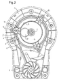
- die Anordnung des feststehenden Zahnkranzes eines Planetengetriebes an dem unteren Gehäuseteil einer Küchenmaschine in Draufsicht,
- Fig. 3
- in perspektivischer Darstellung eine Draufsicht auf den feststehenden Zahnkranz und
- Fig. 4
- in perspektivischer Darstellung eine Unteransicht des feststehenden Zahnkranzes.
- Mit 1 ist der untere Gehäuseteil einer Küchenmaschine bezeichnet. An diesem ist ein topfförmig ausgebildetes Getrieberad 2 drehbar gelagert. An dem Topfmantel 3 des Getrieberades 2 ist eine Außenverzahnung 4 für einen vom Antriebsmotor 5 der Küchenmaschine angetriebenen Zahnriemen 6 vorhanden. Im Topfraum 7 des Getriebesrades 2 ist der feststehende Zahnkranz 8 eines Planetengetriebes angeordnet. Im Innenraum 9 des Zahnkranzes 8 sind mehrere über ein in der Mitte des Topfbodens 10 des Getrieberades 2 angeformtes Sonnenrad 11 angetriebene Planetenräder 12, von denen nur eines in der Fig. 2 dargestellt ist, angeordnet. An der Außenseite des Zahnkranzes 8 sind mit gleichmäßigem Umfangsabstand drei nach radial außen abragende Tragarme 13 angeformt. Die Tragarme 13 weisen eine U-förmige Abknickung 14 auf, mit der sie den Topfmantel 3 des Getrieberades 2 übergreifen. Am freien Ende der Tragarme 13 befinden sich hülsenförmige Befestigungselemente 15, die im Innern einen Zwischenboden 16 aufweisen. Die hülsenförmigen Befestigungselemente 15 bilden somit zwei einander gegenüberliegende Aufnahmen 17, in Form eines Rohrstutzens, in die jeweils ein aus elastischem Material bestehendes Rohrteil 18 eingesetzt ist.
- Das in der zu dem unteren Gehäuseteil 1 gerichteten Aufnahme 17 eingesetzte Rohrteil 18 ist mit seiner Rohröffnung 19 auf einen am unteren Gehäuseteil 1 angeformten Zapfen 20 aufgesteckt. Hierdurch wird der Zahnkranz 8 am unteren Gehäuseteil 1 gehalten. Dabei wird durch das elastische Rohrteil 18 eine Berührung von starren Teilen der Tragarme 13, somit also auch des Zahnkranzes 8, mit starren Teilen des Gehäuses 1, also den Zapfen 20, vermieden. Infolge dieser Entkoppelung von starren Teilen ergibt sich durch das elastische Rohrteil 18 eine ausgezeichnete Geräuschdämpfung.
- Das obere Gehäuseteil 21 der Küchenmaschine ist mit an ihm angeformten Haltezapfen 22 in die Rohröffnung 19 des in die obenliegende Aufnahme 17 eingesetzten Rohrteiles 18 eingesteckt. Damit ist auch das obere Gehäuseteil 21 schwingungsmäßig von dem Zahnkranz 8 abgekoppelt, so daß auch auf das obere Gehäuseteil 21 Geräusche nur in stark gedämpfter Form übertragen werden können. Damit wird die Geräuschdämpfung insgesamt weiter verbessert. Die Rohrteile 18 besitzen aufgrund ihrer geometrischen Form eine besonders weiche Charakteristik, wodurch sich eine besonders gute Geräuschdämpfung ergibt.
- An der Außenseite des Zahnkranzes 8 ist ferner ein aus elastischem Material bestehender Haltering 23 aufgesteckt. Der Haltering 23 greift bei aufgesetztem Gehäuseoberteil 21 in einen an diesem vorgesehenen Ringbund 14 ein. Hlerdurch ergibt sich eine weitere elastische Halterung und insbesondere auch eine gute Zentrierung des Zahnkranzes 8. Der Zahnkranz 8 ist damit sowohl von dem unteren als auch dem oberen Gehäuseteil 1 und 21 schwingungselastisch entkoppelt.
- Durch diese vollständige elastische Entkoppelung der Antriebsteile von den Gehäuseteilen 1 und 21 der Küchenmaschine ergibt sich zusätzlich auch eine Abflachung des Anlaufmomentes beim Einschalten des Antriebsmotors 5. Beim Anlauf des Antriebsmotors 5 wirkt der Anfahrstoß zunächst auf die elastischen Elemente, insbesondere auf die Rohrteile 18, wodurch diese zunächst gespannt werden. Erst danach setzt die Drehbewegung der Getriebeteile ein. Eine solche Dämpfung des Anfahrstoßes ist zur Schonung des Antriebsmotors 5 sehr erwünscht.
Claims (9)
- Haushaltsgerät mit einem wenigstens zwei Gehäuseteile (1, 21) aufweisenden Gehäuse und mit einem von einem elektrischen Antriebsaggregat (5) angetriebenen Getriebe, das an wenigstens einem der Gehäuseteile unter Zwischenschaltung schwingungsdämpfender Elemente (18) festgesetzt ist, dadurch gekennzeichnet, dass das Getriebe an beiden Gehäuseteilen (1, 21) befestigt ist und das an den Befestigungsstellen (15, 20, 22) die schwingungsdämpfenden Elemente (18) derart eingefügt sind, dass ein direkter Kontakt zwischen dem Getriebe und den Gehäuseteilen (1, 21) verhindert ist und das Getriebe über die schwingungsdämpfenden Elemente (18) in den Gehäuseteilen (1, 21) gehalten ist.
- Haushaltsgerät nach Anspruch 1, dadurch gekennzeichnet, daß das Getriebe zu seiner Befestigung Tragarme (13) mit Aufnahmen (17) aufweist, an welchem die schwingungsdämpfenden Elemente (18) als Zwischenlage zwischen den zur Befestigung des Getriebes dienenden Gehäuseteilen (1, 21) anordenbar sind.
- Haushaltsgerät nach Anspruch 2, dadurch gekennzeichnet, daß die Aufnahmen als zumindest annähernd vertikal angeordnete Haltezapfen ausgebildet sind, an welchen rohrähnliches schwingungsdämpfendes Element form- und/oder kraftschlüssig aufgesteckt ist, wobei die Elemente in an deren Außenkontur angepaßte Aufnahmen an den Gehäuseteilen (1, 21) einfügbar sind.
- Haushaltsgerät nach Anspruch 3, dadurch gekennzeichnet, daß jeweils ein Haltezapfen beidseits an den Tragarmen (4) vorgesehen ist, auf welchem ein aus elastomerem Material bestehendes, als Element dienendes Rohrteil (18) aufgesteckt ist, das mit seinem Rohrmantel in an beiden Gehäuseteilen (1, 21) angeordneten Rohrstücke eingefügt ist.
- Haushaltsgerät nach Anspruch 2, dadurch gekennzeichnet, daß die Aufnahmen (17) als an den Tragarmen (13) zumindest annähernd vertikal angeordnete Rohrstutzen ausgebildet sind, in welche ein rohrähnliches schwingungsdämpfendes Element (18) form- und/oder kraftschlüssig eingesteckt ist, wobei die Elemente (18) an den Gehäuseteilen (1, 21) angeordnete Haltezapfen (20, 22) einfügbar sind.
- Haushaltsgerät nach Anspruch 5, dadurch gekennzeichnet, daß jeweils ein Rohrstutzen (17) beidseits an den Tragarmen (13) vorgesehen ist, in welchem ein aus elastomerem Material bestehendes, als Element dienendes Rohrteil (18) eingesteckt ist, das mit seiner Rohröffnung (19) in an beiden Gehäuseteilen (1, 21) angeordneten Haltezapfen (20, 22) aufsteckbar ist.
- Haushaltsgerät nach einem der Ansprüche 1 bis 6, dadurch gekennzeichnet, daß die Tragarme (13) mit einer U-förmigen Abknickung versehen sind.
- Küchenmaschine mit einem elektrischen Antrieb (5) zum Antrieb eines Planetengetriebes und einem Gehäuse, bestehend aus einem Gehäuseoberteil (21) und einem Gehäuseunterteil (1), wobei das Planetengetriebe einen ortsfesten Zahnkranz (8) besitzt, der an wenigstens einem der Gehäuseteile unter Zwischenhaltung schwingungsdämpfender Elemente (18) fertgesetst ist, dadurch gekennzeichnet, dass der von Tragarmen (13) befestigt ist, wobei die Tragarme nach einem der Ansprüche 2-7 ausgebildet sind.
- Küchemmaschine nach Anspruch 8 dadurch gekennzeichnet, daß der Zahnkranz (8) außerdem mittels eines aufgesetzten, aus elastischem Material bestehenden Halteringes (23) in einem am Gehäuseoberteil (21) ausgebildeten Ringbund (14) gehalten ist.
Priority Applications (1)
| Application Number | Priority Date | Filing Date | Title |
|---|---|---|---|
| SI200130635T SI1274334T1 (sl) | 2000-03-31 | 2001-02-23 | Gospodinjski aparat |
Applications Claiming Priority (3)
| Application Number | Priority Date | Filing Date | Title |
|---|---|---|---|
| DE10016330A DE10016330A1 (de) | 2000-03-31 | 2000-03-31 | Haushaltgerät |
| DE10016330 | 2000-03-31 | ||
| PCT/EP2001/002086 WO2001074221A1 (de) | 2000-03-31 | 2001-02-23 | Haushaltsgerät |
Publications (2)
| Publication Number | Publication Date |
|---|---|
| EP1274334A1 EP1274334A1 (de) | 2003-01-15 |
| EP1274334B1 true EP1274334B1 (de) | 2006-07-12 |
Family
ID=7637307
Family Applications (1)
| Application Number | Title | Priority Date | Filing Date |
|---|---|---|---|
| EP01917021A Expired - Lifetime EP1274334B1 (de) | 2000-03-31 | 2001-02-23 | Haushaltsgerät |
Country Status (6)
| Country | Link |
|---|---|
| US (1) | US6736539B2 (de) |
| EP (1) | EP1274334B1 (de) |
| CN (1) | CN1420738A (de) |
| AT (1) | ATE332664T1 (de) |
| DE (2) | DE10016330A1 (de) |
| WO (1) | WO2001074221A1 (de) |
Cited By (1)
| Publication number | Priority date | Publication date | Assignee | Title |
|---|---|---|---|---|
| US10995042B2 (en) * | 2018-11-13 | 2021-05-04 | Whirlpool Corporation | Food waste recycling appliance |
Families Citing this family (9)
| Publication number | Priority date | Publication date | Assignee | Title |
|---|---|---|---|---|
| US6364226B1 (en) * | 2000-05-01 | 2002-04-02 | Conair Corporation | Food processor with reversible motor feature |
| DE102005040547A1 (de) * | 2005-08-26 | 2007-03-01 | BSH Bosch und Siemens Hausgeräte GmbH | Elektromotorisches Küchengerät mit einem Bajonettverschluss für einen Elektromotor und eine Getriebestufe und Verfahren zum Montieren eines elektromotorischen Küchengeräts |
| DE102007060679A1 (de) | 2007-12-17 | 2009-06-25 | BSH Bosch und Siemens Hausgeräte GmbH | Verfahren und Vorrichtung zum Unterdrücken, zumindest aber zum Verringern von störenden Vibrationen in einem motorbetriebenen Gerät, insbesondere einem Hausgerät |
| FR2942123B1 (fr) * | 2009-02-16 | 2011-02-18 | Vmi | Boite de vitesse pour batteur melangeur |
| US9084512B2 (en) * | 2011-05-16 | 2015-07-21 | Vita-Mix Management Corporation | Blender base |
| DE102011087287A1 (de) | 2011-11-29 | 2013-05-29 | BSH Bosch und Siemens Hausgeräte GmbH | Bearbeitungsaufsatz für ein elektrisch betreibbares Küchengerät sowie Küchengerät |
| US10413109B2 (en) | 2013-03-13 | 2019-09-17 | Spectrum Brands, Inc. | Food preparation appliance for steam cooking and food processing |
| GB2516243B (en) * | 2013-07-16 | 2018-02-07 | Kenwood Ltd | Food mixers |
| US11412893B2 (en) | 2016-11-01 | 2022-08-16 | Vita-Mix Management Corporation | Blending volume reducing device |
Family Cites Families (6)
| Publication number | Priority date | Publication date | Assignee | Title |
|---|---|---|---|---|
| DE3045088A1 (de) * | 1980-11-29 | 1982-07-01 | Fichtel & Sachs Ag, 8720 Schweinfurt | Getriebe fuer eine haushaltskuechenmaschine |
| US4783173A (en) * | 1987-10-26 | 1988-11-08 | Sunbeam Corporation | Combined washer and collar for supporting a motor |
| FR2655531A1 (fr) * | 1989-12-13 | 1991-06-14 | Moulinex Sa | Appareil de petrissage et de cuisson. |
| DE4215882A1 (de) * | 1992-05-14 | 1993-11-18 | Braun Ag | Küchenmaschine |
| DE10016301A1 (de) * | 2000-03-31 | 2001-10-04 | Bsh Bosch Siemens Hausgeraete | Elektrisches Haushaltsgerät |
| US6593674B2 (en) * | 2001-02-26 | 2003-07-15 | Woodward Governor Company | Vibration isolator and actuator incorporating same for isolating integral electronics |
-
2000
- 2000-03-31 DE DE10016330A patent/DE10016330A1/de not_active Withdrawn
-
2001
- 2001-02-23 DE DE50110449T patent/DE50110449D1/de not_active Expired - Lifetime
- 2001-02-23 AT AT01917021T patent/ATE332664T1/de not_active IP Right Cessation
- 2001-02-23 WO PCT/EP2001/002086 patent/WO2001074221A1/de not_active Ceased
- 2001-02-23 CN CN01807516.9A patent/CN1420738A/zh active Pending
- 2001-02-23 EP EP01917021A patent/EP1274334B1/de not_active Expired - Lifetime
-
2002
- 2002-09-30 US US10/261,192 patent/US6736539B2/en not_active Expired - Fee Related
Cited By (1)
| Publication number | Priority date | Publication date | Assignee | Title |
|---|---|---|---|---|
| US10995042B2 (en) * | 2018-11-13 | 2021-05-04 | Whirlpool Corporation | Food waste recycling appliance |
Also Published As
| Publication number | Publication date |
|---|---|
| US6736539B2 (en) | 2004-05-18 |
| EP1274334A1 (de) | 2003-01-15 |
| DE50110449D1 (de) | 2006-08-24 |
| CN1420738A (zh) | 2003-05-28 |
| WO2001074221A1 (de) | 2001-10-11 |
| ATE332664T1 (de) | 2006-08-15 |
| US20030076739A1 (en) | 2003-04-24 |
| DE10016330A1 (de) | 2001-10-04 |
Similar Documents
| Publication | Publication Date | Title |
|---|---|---|
| EP0871278B1 (de) | Anordnung zur schwingungsisolierenden Aufhängung eines Elektromotors | |
| EP1212824B1 (de) | Vorrichtung zur schwingungsisolierenden halterung eines elektromotors | |
| EP0785742B1 (de) | Arbeitsgerät zum rühren oder zerkleinern von nahrungsmitteln | |
| DE4334124A1 (de) | Vorrichtung zum Aufnehmen eines Elektromotors | |
| DE3103782C2 (de) | Elektromotor, insbesondere Gleichstrom-Kleinmotor | |
| DE102011053869A1 (de) | Riemenspannvorrichtung für einen Riementrieb und Aggregatanordnung mit Riemenspannvorrichtung | |
| EP3122604B1 (de) | Kraftfahrzeugaktuator, insbesondere bremsaktuator | |
| DE102012101139A1 (de) | Permanentmagnetmotor | |
| EP1274334A1 (de) | Haushaltsgerät | |
| DE102012109013A1 (de) | Küchenmaschine und Motoranordnung | |
| DE102011010087A1 (de) | Anordnung mit Verbrennungskraftmaschine und daran angekoppeltem Planetengetriebe | |
| DE102009002975A1 (de) | Handwerkzeugmaschine, insbesondere Elektrohandwerkzeugmaschine | |
| DE4416449A1 (de) | Baueinheit aus einer Hydromaschine (Hydropumpe oder Hydromotor) und einem Träger | |
| EP1196699A1 (de) | Leistungsverzweigungsgetriebe | |
| DE102012110791A1 (de) | Kraftfahrzeugaktuator | |
| EP0855782B1 (de) | Geräuscharmer Elektromotor, insbesondere zum Antrieb eines Kraftfahrzeug-Lüfters | |
| DE102010032658A1 (de) | Drehmomentübertragungseinrichtung | |
| EP3482480B1 (de) | Befestigungsanordnung eines elektromotors und sitz | |
| DE102017214116A1 (de) | Antriebsvorrichtung für einen Fensterheber | |
| DE8903226U1 (de) | Dichtung für Elektro-Haushaltsgeräte | |
| DE2817170C2 (de) | Innenrüttler | |
| EP1529976A1 (de) | Schalldämpfungsanordnung | |
| DE10033870A1 (de) | Hydraulikeinheit | |
| DE20106789U1 (de) | Motorischer Verstellantrieb für ein Kraftfahrzeug | |
| DE102006014762A1 (de) | Kunststoffelement |
Legal Events
| Date | Code | Title | Description |
|---|---|---|---|
| PUAI | Public reference made under article 153(3) epc to a published international application that has entered the european phase |
Free format text: ORIGINAL CODE: 0009012 |
|
| 17P | Request for examination filed |
Effective date: 20021031 |
|
| AK | Designated contracting states |
Kind code of ref document: A1 Designated state(s): AT BE CH CY DE DK ES FI FR GB GR IE IT LI LU MC NL PT SE TR |
|
| AX | Request for extension of the european patent |
Free format text: SI |
|
| 17Q | First examination report despatched |
Effective date: 20030226 |
|
| RAP1 | Party data changed (applicant data changed or rights of an application transferred) |
Owner name: BSH BOSCH UND SIEMENS HAUSGERAETE GMBH |
|
| GRAP | Despatch of communication of intention to grant a patent |
Free format text: ORIGINAL CODE: EPIDOSNIGR1 |
|
| GRAS | Grant fee paid |
Free format text: ORIGINAL CODE: EPIDOSNIGR3 |
|
| GRAA | (expected) grant |
Free format text: ORIGINAL CODE: 0009210 |
|
| AK | Designated contracting states |
Kind code of ref document: B1 Designated state(s): AT BE CH CY DE DK ES FI FR GB GR IE IT LI LU MC NL PT SE TR |
|
| AX | Request for extension of the european patent |
Extension state: SI |
|
| PG25 | Lapsed in a contracting state [announced via postgrant information from national office to epo] |
Ref country code: IT Free format text: LAPSE BECAUSE OF FAILURE TO SUBMIT A TRANSLATION OF THE DESCRIPTION OR TO PAY THE FEE WITHIN THE PRESCRIBED TIME-LIMIT;WARNING: LAPSES OF ITALIAN PATENTS WITH EFFECTIVE DATE BEFORE 2007 MAY HAVE OCCURRED AT ANY TIME BEFORE 2007. THE CORRECT EFFECTIVE DATE MAY BE DIFFERENT FROM THE ONE RECORDED. Effective date: 20060712 Ref country code: IE Free format text: LAPSE BECAUSE OF FAILURE TO SUBMIT A TRANSLATION OF THE DESCRIPTION OR TO PAY THE FEE WITHIN THE PRESCRIBED TIME-LIMIT Effective date: 20060712 Ref country code: NL Free format text: LAPSE BECAUSE OF FAILURE TO SUBMIT A TRANSLATION OF THE DESCRIPTION OR TO PAY THE FEE WITHIN THE PRESCRIBED TIME-LIMIT Effective date: 20060712 Ref country code: FI Free format text: LAPSE BECAUSE OF FAILURE TO SUBMIT A TRANSLATION OF THE DESCRIPTION OR TO PAY THE FEE WITHIN THE PRESCRIBED TIME-LIMIT Effective date: 20060712 |
|
| REG | Reference to a national code |
Ref country code: GB Ref legal event code: FG4D Free format text: NOT ENGLISH |
|
| REG | Reference to a national code |
Ref country code: CH Ref legal event code: EP |
|
| GBT | Gb: translation of ep patent filed (gb section 77(6)(a)/1977) |
Effective date: 20060725 |
|
| REG | Reference to a national code |
Ref country code: IE Ref legal event code: FG4D Free format text: LANGUAGE OF EP DOCUMENT: GERMAN |
|
| REF | Corresponds to: |
Ref document number: 50110449 Country of ref document: DE Date of ref document: 20060824 Kind code of ref document: P |
|
| PG25 | Lapsed in a contracting state [announced via postgrant information from national office to epo] |
Ref country code: DK Free format text: LAPSE BECAUSE OF FAILURE TO SUBMIT A TRANSLATION OF THE DESCRIPTION OR TO PAY THE FEE WITHIN THE PRESCRIBED TIME-LIMIT Effective date: 20061012 |
|
| PG25 | Lapsed in a contracting state [announced via postgrant information from national office to epo] |
Ref country code: ES Free format text: LAPSE BECAUSE OF FAILURE TO SUBMIT A TRANSLATION OF THE DESCRIPTION OR TO PAY THE FEE WITHIN THE PRESCRIBED TIME-LIMIT Effective date: 20061023 |
|
| REG | Reference to a national code |
Ref country code: SE Ref legal event code: TRGR |
|
| PG25 | Lapsed in a contracting state [announced via postgrant information from national office to epo] |
Ref country code: PT Free format text: LAPSE BECAUSE OF FAILURE TO SUBMIT A TRANSLATION OF THE DESCRIPTION OR TO PAY THE FEE WITHIN THE PRESCRIBED TIME-LIMIT Effective date: 20061212 |
|
| ET | Fr: translation filed | ||
| NLV1 | Nl: lapsed or annulled due to failure to fulfill the requirements of art. 29p and 29m of the patents act | ||
| REG | Reference to a national code |
Ref country code: IE Ref legal event code: FD4D |
|
| PG25 | Lapsed in a contracting state [announced via postgrant information from national office to epo] |
Ref country code: CH Free format text: LAPSE BECAUSE OF NON-PAYMENT OF DUE FEES Effective date: 20070228 Ref country code: MC Free format text: LAPSE BECAUSE OF NON-PAYMENT OF DUE FEES Effective date: 20070228 Ref country code: LI Free format text: LAPSE BECAUSE OF NON-PAYMENT OF DUE FEES Effective date: 20070228 |
|
| PLBE | No opposition filed within time limit |
Free format text: ORIGINAL CODE: 0009261 |
|
| STAA | Information on the status of an ep patent application or granted ep patent |
Free format text: STATUS: NO OPPOSITION FILED WITHIN TIME LIMIT |
|
| 26N | No opposition filed |
Effective date: 20070413 |
|
| REG | Reference to a national code |
Ref country code: CH Ref legal event code: PL |
|
| BERE | Be: lapsed |
Owner name: BSH BOSCH UND SIEMENS HAUSGERATE G.M.B.H. Effective date: 20070228 |
|
| PG25 | Lapsed in a contracting state [announced via postgrant information from national office to epo] |
Ref country code: BE Free format text: LAPSE BECAUSE OF NON-PAYMENT OF DUE FEES Effective date: 20070228 |
|
| PG25 | Lapsed in a contracting state [announced via postgrant information from national office to epo] |
Ref country code: GR Free format text: LAPSE BECAUSE OF FAILURE TO SUBMIT A TRANSLATION OF THE DESCRIPTION OR TO PAY THE FEE WITHIN THE PRESCRIBED TIME-LIMIT Effective date: 20061013 |
|
| PG25 | Lapsed in a contracting state [announced via postgrant information from national office to epo] |
Ref country code: AT Free format text: LAPSE BECAUSE OF NON-PAYMENT OF DUE FEES Effective date: 20070223 |
|
| PG25 | Lapsed in a contracting state [announced via postgrant information from national office to epo] |
Ref country code: CY Free format text: LAPSE BECAUSE OF FAILURE TO SUBMIT A TRANSLATION OF THE DESCRIPTION OR TO PAY THE FEE WITHIN THE PRESCRIBED TIME-LIMIT Effective date: 20060712 Ref country code: LU Free format text: LAPSE BECAUSE OF NON-PAYMENT OF DUE FEES Effective date: 20070223 |
|
| PGFP | Annual fee paid to national office [announced via postgrant information from national office to epo] |
Ref country code: TR Payment date: 20120223 Year of fee payment: 12 |
|
| PGFP | Annual fee paid to national office [announced via postgrant information from national office to epo] |
Ref country code: SE Payment date: 20120221 Year of fee payment: 12 |
|
| REG | Reference to a national code |
Ref country code: SE Ref legal event code: EUG |
|
| REG | Reference to a national code |
Ref country code: SI Ref legal event code: KO00 Effective date: 20130925 |
|
| PG25 | Lapsed in a contracting state [announced via postgrant information from national office to epo] |
Ref country code: SE Free format text: LAPSE BECAUSE OF NON-PAYMENT OF DUE FEES Effective date: 20130224 |
|
| PG25 | Lapsed in a contracting state [announced via postgrant information from national office to epo] |
Ref country code: TR Free format text: LAPSE BECAUSE OF NON-PAYMENT OF DUE FEES Effective date: 20130223 |
|
| REG | Reference to a national code |
Ref country code: FR Ref legal event code: PLFP Year of fee payment: 15 |
|
| REG | Reference to a national code |
Ref country code: DE Ref legal event code: R081 Ref document number: 50110449 Country of ref document: DE Owner name: BSH HAUSGERAETE GMBH, DE Free format text: FORMER OWNER: BSH BOSCH UND SIEMENS HAUSGERAETE GMBH, 81739 MUENCHEN, DE Effective date: 20150402 |
|
| REG | Reference to a national code |
Ref country code: FR Ref legal event code: CD Owner name: BSH HAUSGERATE GMBH Effective date: 20151022 |
|
| REG | Reference to a national code |
Ref country code: FR Ref legal event code: PLFP Year of fee payment: 16 |
|
| REG | Reference to a national code |
Ref country code: FR Ref legal event code: PLFP Year of fee payment: 17 |
|
| PGFP | Annual fee paid to national office [announced via postgrant information from national office to epo] |
Ref country code: DE Payment date: 20170228 Year of fee payment: 17 |
|
| REG | Reference to a national code |
Ref country code: FR Ref legal event code: PLFP Year of fee payment: 18 |
|
| PGFP | Annual fee paid to national office [announced via postgrant information from national office to epo] |
Ref country code: GB Payment date: 20180221 Year of fee payment: 18 |
|
| PGFP | Annual fee paid to national office [announced via postgrant information from national office to epo] |
Ref country code: FR Payment date: 20180222 Year of fee payment: 18 Ref country code: IT Payment date: 20180221 Year of fee payment: 18 |
|
| REG | Reference to a national code |
Ref country code: DE Ref legal event code: R119 Ref document number: 50110449 Country of ref document: DE |
|
| PG25 | Lapsed in a contracting state [announced via postgrant information from national office to epo] |
Ref country code: DE Free format text: LAPSE BECAUSE OF NON-PAYMENT OF DUE FEES Effective date: 20180901 |
|
| GBPC | Gb: european patent ceased through non-payment of renewal fee |
Effective date: 20190223 |
|
| PG25 | Lapsed in a contracting state [announced via postgrant information from national office to epo] |
Ref country code: GB Free format text: LAPSE BECAUSE OF NON-PAYMENT OF DUE FEES Effective date: 20190223 |
|
| PG25 | Lapsed in a contracting state [announced via postgrant information from national office to epo] |
Ref country code: FR Free format text: LAPSE BECAUSE OF NON-PAYMENT OF DUE FEES Effective date: 20190228 Ref country code: IT Free format text: LAPSE BECAUSE OF NON-PAYMENT OF DUE FEES Effective date: 20190223 |