EP1275311A2 - Dispositif pour préparer un courant de fibres dans l'industrie du tabac - Google Patents
Dispositif pour préparer un courant de fibres dans l'industrie du tabac Download PDFInfo
- Publication number
- EP1275311A2 EP1275311A2 EP02012958A EP02012958A EP1275311A2 EP 1275311 A2 EP1275311 A2 EP 1275311A2 EP 02012958 A EP02012958 A EP 02012958A EP 02012958 A EP02012958 A EP 02012958A EP 1275311 A2 EP1275311 A2 EP 1275311A2
- Authority
- EP
- European Patent Office
- Prior art keywords
- strand
- fiber
- trimming
- tobacco
- trim
- Prior art date
- Legal status (The legal status is an assumption and is not a legal conclusion. Google has not performed a legal analysis and makes no representation as to the accuracy of the status listed.)
- Granted
Links
Images



Classifications
-
- A—HUMAN NECESSITIES
- A24—TOBACCO; CIGARS; CIGARETTES; SIMULATED SMOKING DEVICES; SMOKERS' REQUISITES
- A24C—MACHINES FOR MAKING CIGARS OR CIGARETTES
- A24C5/00—Making cigarettes; Making tipping materials for, or attaching filters or mouthpieces to, cigars or cigarettes
- A24C5/14—Machines of the continuous-rod type
- A24C5/18—Forming the rod
- A24C5/1835—Multiple rod making devices
-
- A—HUMAN NECESSITIES
- A24—TOBACCO; CIGARS; CIGARETTES; SIMULATED SMOKING DEVICES; SMOKERS' REQUISITES
- A24C—MACHINES FOR MAKING CIGARS OR CIGARETTES
- A24C5/00—Making cigarettes; Making tipping materials for, or attaching filters or mouthpieces to, cigars or cigarettes
- A24C5/14—Machines of the continuous-rod type
- A24C5/18—Forming the rod
- A24C5/1814—Forming the rod containing parts of different densities, e.g. dense ends
-
- A—HUMAN NECESSITIES
- A24—TOBACCO; CIGARS; CIGARETTES; SIMULATED SMOKING DEVICES; SMOKERS' REQUISITES
- A24C—MACHINES FOR MAKING CIGARS OR CIGARETTES
- A24C5/00—Making cigarettes; Making tipping materials for, or attaching filters or mouthpieces to, cigars or cigarettes
- A24C5/14—Machines of the continuous-rod type
- A24C5/18—Forming the rod
- A24C5/1842—Trimming devices
Definitions
- the invention relates to a device for preparing at least one Fiber strands of a tobacco processing industry strand machine for further processing in the strand machine, provided for each fiber strand is: a strand conveyor in a strand guide channel for conveying the fiber strand, a trimmer for removing excess fibers from the Fiber strand.
- a strand of fibers can be, for example, a strand of tobacco fibers act.
- a rod machine of the tobacco processing industry it can be for example, a double-strand machine for the production of cigarettes or double filter cigarettes act.
- DE 4333046 A1 of the applicant, US 5,526,826 of Applicant corresponds to a device of the type described above.
- a repellent for removing the excess tobacco fibers here is one rotating body serving as a deflector surface provided which one on its side facing the trim discs Carries circular knife.
- the object of the present invention is to improve such devices.
- Such a section-wise reinforcement is used in the production of Tobacco fiber cigarettes, also known as head reinforcement, in the prior art Technology is known for example from DE 3837201 A1, which is US Pat. No. 4,883,076 corresponds; in these known devices for head reinforcement, two in a plane with the tobacco rod arranged clamping discs used as Trim disks to take excess of the tobacco rod and on their Have pockets in which a certain excess on the The tobacco rod remains standing, so that it later closes when the rod is compacted leads to a more compacted area. Practice these pockets in the trim discs however, additional forces are exerted on the tobacco rod, leading to a spread of weight lead cigarettes manufactured in this way.
- the inventive design of the device for Preparing a strand of fiber improves the quality of the head reinforcement. Because Due to the moving side walls, the head reinforcement is in the fiber strand introduced without relative movement between head reinforcement and fiber strand. The head reinforcement can therefore be introduced much more regularly and precisely.
- the moving side wall as at least one circumferential belt, preferably designed as a toothed belt.
- a toothed belt can be easily driven using toothed pulleys.
- only one or both side walls of the strand guide channel with the fiber strand and have only one or both side walls have the recesses for introducing the head reinforcements on.
- a Control unit synchronize the running speed of the side walls to each other, in which the control unit the speed of drive rollers for the side walls controls.
- This can advantageously achieve that the intended Recesses in both side walls always at the same level with the Run along the fiber strand.
- the repellent is formed as a substantially frustoconical body of revolution
- the axis of rotation preferably runs perpendicular to the direction of movement of the strand and preferably parallel to the axes of rotation of the trim discs.
- the outer surface of the rotating body with that of the trim discs adjacent end face of the rotating body an acute angle between 5 ° and forms about 40 °, which angle at least on parts of the lateral surface increasing distance of the lateral surface from the end face or the trim discs increases. It is particularly advantageous if the angle increases steadily by one to ensure fluid repellency of the fibers. It is even more preferred if the angle increases up to 90 ° and, if necessary, beyond it at an obtuse angle of passes up to 120 °. This has also proven to be advantageous for gentle distraction of the tobacco fibers removed.
- the device can also be used to prepare two parallel fiber strands, For example, in a strand machine designed as a double strand machine.
- the fiber strands are each from a strand conveyor in a strand guide channel promoted and each by a trimmer for further processing in prepared the double strand machine.
- the diameter each of the trim discs adjacent to the parallel strand the distance of the Fiber strands is adjusted.
- the diameter of this Trim discs roughly corresponds to the distance between the fiber strands. On this can also be the case with the narrow spaces prevailing in double-strand machines
- the combination of smooth trim disks according to the invention has limited space and troughed, moving side wall can be realized.
- a is used as a receptacle for parts of the Device, preferably for the strand guide channel, in particular for the whole inventive device, serving housing as an extruded profile, further preferred formed as an extruded aluminum profile. It can in this profile from from the start receptacles for screws for fastening components of the device according to the invention may be provided.
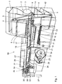
- FIG. 1 shows a perspective view of a single-strand cigarette rod machine 50, i.e. a strand machine for processing tobacco fibers into one Tobacco fiber strand for the manufacture of cigarettes.
- the cigarette rod machine 50 serves as an embodiment for a machine in which a first embodiment the device according to the invention, as below in particular with reference to FIG. 2 described, can be used.
- a second embodiment of the Device according to the invention, as below in particular with reference to FIG. 3 described, can be used in a double strand machine. How it works the cigarette rod machine 50 is as follows:
- a pre-distributor 2 is loaded with tobacco in portions from a lock 1.
- a Removal roller 3 of the pre-distributor 2 supplements a storage container 4 in a controlled manner Tobacco, from which a steep conveyor takes 5 tobacco and a stowage shaft 6 controlled feed.
- a pin roller 7 removes one from the storage shaft 6 uniform flow of tobacco by a knockout roller 8 from the pins of the Pin roller 7 knocked out and on at a constant speed peripheral scattering cloth 9 is thrown.
- a tobacco fleece formed on the spreading cloth 9 is thrown into a viewing device 11, which essentially consists of a There is an air curtain that larger or heavier parts of tobacco pass through while all other tobacco particles from the air into one of a pin roller 12 and a wall 13 funnel 14 formed are steered.
- the tobacco is in a strand guide channel 16 hurled against a strand conveyor 17 on the the tobacco is held and sucked in by means of air sucked into a vacuum chamber 18 Tobacco rod is thrown up.
- Strand conveyor 17 is referred, for example, to DE 4215059 by the applicant.
- the Strand guide channel 16 is described below with reference in particular to FIGS. 3, 4 and 6 described in more detail.
- Trimmer 19 removes excess tobacco from the tobacco rod, which then is placed on a cigarette paper strip 21 guided in synchronism.
- the Cigarette paper strip 21 is pulled off a bobbin 22 by a printing unit 23 out and placed on a driven format belt 24.
- Format tape 24 transports the tobacco rod and the cigarette paper strip 21 through a format 26, in which the cigarette paper strip 21 is folded around the tobacco rod so that still an edge protrudes from a glue apparatus, not shown in known Way is glued. Then the adhesive seam is closed and one Tandem seam plate 27 dried.
- a cigarette rod 28 formed in this way runs through Strand density measuring device 29, which controls the device 19, and is operated by a Knife apparatus 31 cut into double-length cigarettes 32.
- the double length Cigarettes 32 are controlled by arms 33
- Single cigarettes can be shared.
- Conveyor belts 39, 41 convey excess tobacco into a container 42 arranged below the storage container 4, from which the recycled tobacco is removed from the steep conveyor 5 again.
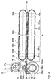
- FIG. 2 shows a schematic top view of the first embodiment of the invention, that is used in the cigarette rod machine 50 shown in FIG. 1.
- the Figure shows the strand guide channel 16, hereinafter called tobacco channel 16.
- tobacco channel 16 is a tobacco fiber strand 52.
- the sidewalls of the tobacco duct 16 are along a section A of backs 60a and 60b from over pulleys 54a and 54b rotating and of drive rollers 56a and 56b corresponding to the Conveying speed of the strand conveyor 17 driven toothed belt 58a and 58b formed.
- the backs 60a and 60b thus form with the tobacco fiber strand 52 moving side walls for the tobacco channel 16.
- the trimming device 19 has two rotating in opposite directions, in a predetermined Distance from the strand conveyor 17 almost in the middle 64 of the tobacco channel 16 with smooth trim disks 68a and 68b touching their respective circumference 66a or 66b and one of the trim disks 68a, 68b on the one facing away from the strand conveyor 17 Side assigned, substantially frustoconical deflector 70 to Remove the excess tobacco fibers.
- Trim disks 68a and 68b are driven Trim disks 68a and 68b via a drive belt 72 that runs from one in one Housing 73 arranged drive 74 is driven and via a tension roller 76 is excited.
- the deflector wheel 70 is driven by a second belt 78, which sits on a shaft 80 of the trim disk 68a.
- the trim disk 68a has approximately three times the diameter of the trim disc 68b.
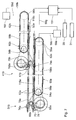
- FIG. 3 shows a schematic top view of the second embodiment of the invention, the generation in a double strand machine, not shown of two parallel fiber strands 116a and 116b is used. How it works corresponds essentially to that of the embodiment of FIG. 1 detailed description can therefore be omitted here. Parts with parts of the Embodiment of FIG. 1 are identical, are given the same reference numerals denotes parts that function in their function with parts of the embodiment of FIG. 1 are identical, have the same, but increased by 100 reference numerals designated.
- each tobacco rod 116a or 116b only one idling side wall 58a or 58b is provided.
- the Tobacco strands 116a and 116b only from one side with one along the Provide recesses 62a and 62b with an enlarged cross section in sections. This however, is sufficient to form the head reinforcement 52a.
- the drive rollers 56a and 56b for the toothed belts 58a and 58b are over symbolically shown shafts 56c and 56d driven by motors 56e and 56f.
- the motors 56e and 56f are connected to one another via electrical lines 56g and 56h Control 191 controlled.
- the controller 191 controls the motors 56e and 56f in such a way that the head reinforcements 52a are synchronous in both tobacco strands 116a and 116b are introduced to each other.
- the information about the position of the Control 191 receives head reinforcements 52a from strand density measuring device 29, which in the embodiment shown in Figure 3, the strand density of each of the measures both strands 116a and 116b.
- the strand density measuring device 29 is shown in FIG. 3 represented symbolically.
- controller 191 controls the motors 56e and 56f such that the Head reinforcements 52a in synchronism with the cutting cycle for each strand 116a and 116b provided knife apparatuses 31 for cutting the strands 116a and 116b be introduced.
- the knife apparatuses 31 are also symbolic in FIG. 3 shown.
- a second trimming device 119 is for the tobacco rod 116b intended.
- the structure of the trimming device 119 corresponds to the structure of FIG Trimming device 19, wherein the trimming device 119 is based on the middle between the fiber strands 116a, 116b is mirror-symmetrical to the trimming device 19.
- the trim disks 68b and 168b have a diameter which is approximately that Distance between the two tobacco strands 116a and 116b corresponds.
- Fig. 4 shows a perspective view of those used in the second embodiment Trimming device 119.
- the figure shows housings 169a and 169b and 171 for the drive shafts, not shown, of the trim disks 168a and 168b or the Deflector wheel 170.
- the housings 169a and 169b and 171 are seated on a housing 182, which in turn has a housing 184 of the double-strand machine connected is.
- the outer surface 186 of the deflector wheel 170 forms an acute angle to that adjacent to the trim disks 168a, 168b End face of the deflector wheel 170 or to the surfaces 188a or 188b of the Undersides of the trim discs 168a and 168b.
- the angle takes with it increasing distance to the surfaces 188a and 188b, so that the in the Figure shown shape of the deflector 170 arises.
- Downstream behind the deflector wheel 170 is a deflection plate 190 for deflecting the Deflector wheel 170 removed tobacco fibers.
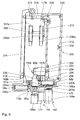
- Fig. 5 shows the second embodiment of FIG. 3 in a partially sectioned Side view, wherein the trimming device 19 is not shown. Parts that those of Figures 3 and 4 correspond to, are designated by the same reference numerals.
- a tobacco duct 116c and 116d is housing 200 shown.
- the tobacco channels 116c and 116d are directed upward from Suction line conveyors 117a and 117b for conveying those not shown Limited tobacco fiber strands.
- the side walls of the tobacco channels 116c, 116d are outward from the backs 60a and 60b of those in housing sections 202a and 202b, respectively circumferential toothed belt 58a and 58b formed.
- the inner side walls form solid channel cheeks 204a and 204b connected to the housing.
- the Suction line conveyors 117a and 117b are moved via deflections 206a and 206b redirected or returned.
- the deflections 206a and 206b sit on one Shaft 208, which in turn has a mounting plate 210 with housing 200 connected is.
- the housing 200 consists of several individual parts: from an extruded profile 212 shown on the right, forming a cavity, from an L-shaped extruded profile 214 shown on the left, an extruded profile 215 serving as a connector, and between the two extruded profiles 212 and 214 lying extrusion profiles 216, 218 and 220 serving as spacers. All extrusion profiles 212, 214, 215, 216, 218 and 220 are made of aluminum.
- the spacer 216 is only used in a double-strand machine to make room for the second tobacco duct 116d. However, the extruded profiles 212, 214, 215, 218, 220 can also be used for a single-strand machine 50 according to FIG. 1.
- the extruded profile 220 is connected to the extruded profile 212 via a connecting piece 222 and a receptacle 224 provided in the extruded profile 212.
- the extruded profile 118 is connected to the extruded profile 212 without the connecting pieces 220 and 222 directly via another receptacle 226 provided in the extruded profile 212.
- the extruded profiles 212, 214, 215, 216, 218 and 220 according to the invention can thus advantageously be used flexibly.
- FIG. 6 shows a schematic plan view of a third embodiment of the invention, which is used in the cigarette rod machine shown in FIG. 1.
- the mode of operation corresponds essentially to that of the first embodiment shown in FIG. 1. A further detailed description of the mode of operation can therefore be dispensed with here.
- Parts which are identical to parts of the embodiment according to FIG. 2 are designated by the same reference numerals, while parts which correspond in their function to parts of the first embodiment according to FIG. 2 are designated by the same reference numerals, but increased by 300.
- a further drive belt 78a is provided, which Drive belt 78a runs over the deflection roller 54a, the shaft of the trim disk 68a, around the shaft of the small trim disk 78b and finally around a tensioning roller 76a around.
- the trim device of the third embodiment according to FIG. 6 modified in this way is designated by the reference number 319.
- Figure 7 shows a schematic plan view of a fourth embodiment of the Invention, which is used in a double strand machine, not shown.
- the mode of operation corresponds essentially to that shown in FIG. 3 second embodiment.
- Parts with parts of the second Embodiment according to Figure 3 are identical, have the same reference numerals referred to as parts in their function with parts of the embodiment 3 agree, with the same, but increased by 400 Reference numerals are designated.
- Figure 4 fourth Embodiment of the invention on a separate drive for the small Trimming discs 68b and 168b dispensed with.
- Trimmer 419 a second driven by the drive roller 56b Drive belt 78b and a tension pulley 76b for tensioning this drive belt 78b provided. Otherwise, the mode of operation is the same as for the trimming device 319.
Landscapes
- Manufacturing Of Cigar And Cigarette Tobacco (AREA)
- Adhesive Tapes (AREA)
- Decoration Of Textiles (AREA)
- Manufacture Of Tobacco Products (AREA)
Applications Claiming Priority (2)
| Application Number | Priority Date | Filing Date | Title |
|---|---|---|---|
| DE10132760 | 2001-07-10 | ||
| DE10132760A DE10132760A1 (de) | 2001-07-10 | 2001-07-10 | Vorrichtung zur Vorbereitung eines Faserstranges der tabakverarbeitenden Industrie |
Publications (3)
| Publication Number | Publication Date |
|---|---|
| EP1275311A2 true EP1275311A2 (fr) | 2003-01-15 |
| EP1275311A3 EP1275311A3 (fr) | 2007-01-03 |
| EP1275311B1 EP1275311B1 (fr) | 2008-11-26 |
Family
ID=7690817
Family Applications (1)
| Application Number | Title | Priority Date | Filing Date |
|---|---|---|---|
| EP02012958A Expired - Lifetime EP1275311B1 (fr) | 2001-07-10 | 2002-06-12 | Dispositif pour préparer un courant de fibres dans l'industrie du tabac |
Country Status (8)
| Country | Link |
|---|---|
| US (1) | US6782889B2 (fr) |
| EP (1) | EP1275311B1 (fr) |
| JP (1) | JP4077671B2 (fr) |
| CN (1) | CN1242707C (fr) |
| AT (1) | ATE415103T1 (fr) |
| DE (2) | DE10132760A1 (fr) |
| ES (1) | ES2315329T3 (fr) |
| PL (1) | PL354966A1 (fr) |
Cited By (1)
| Publication number | Priority date | Publication date | Assignee | Title |
|---|---|---|---|---|
| DE10354745A1 (de) * | 2003-11-21 | 2005-06-30 | Hauni Maschinenbau Ag | Kanalwange |
Families Citing this family (11)
| Publication number | Priority date | Publication date | Assignee | Title |
|---|---|---|---|---|
| PL378645A1 (pl) * | 2006-01-02 | 2007-07-09 | International Tobacco Machinery Poland Spółka Z Ograniczoną Odpowiedzialnością | Urządzenie do transportu i zagęszczania rozdrobnionych produktów |
| US9445627B2 (en) * | 2010-04-23 | 2016-09-20 | R. J. Reynolds Tobacco Company | Tobacco rod manufacturing apparatus |
| DE102011010167B4 (de) * | 2011-02-02 | 2012-12-06 | Hauni Maschinenbau Ag | Strangherstellmaschine zur Herstellung von Produkten der Tabak verarbeitenden Industrie und Formatteil für eine Strangherstellmaschine |
| WO2013098353A1 (fr) * | 2011-12-30 | 2013-07-04 | Philip Morris Products S.A. | Appareil et procédé pour la fourniture d'une bande continue de matériau crêpé en feuille |
| JP5871711B2 (ja) * | 2012-05-21 | 2016-03-01 | ユニ・チャーム株式会社 | トウを含む複数の繊維を有するウエブ部材の切断装置、及び切断方法 |
| JP5836194B2 (ja) * | 2012-05-21 | 2015-12-24 | ユニ・チャーム株式会社 | トウを含む複数の繊維を有する連続ウエブの切断装置、及び切断方法 |
| JP5656915B2 (ja) * | 2012-05-21 | 2015-01-21 | ユニ・チャーム株式会社 | トウを含む複数の繊維を有するウエブ部材の切断装置、及び切断方法 |
| US20170188189A1 (en) * | 2014-07-11 | 2017-06-29 | Telefonaktiebolaget Lm Ericsson (Publ) | A Method, System and Device for Requesting Services At a Mobile Network for One of a Plurality of Mobile User Equipment |
| ES2731245T3 (es) * | 2014-12-19 | 2019-11-14 | Philip Morris Products Sa | Producción de varilla de tabaco con retorno de tabaco |
| US10056964B2 (en) * | 2016-05-20 | 2018-08-21 | Cisco Technology, Inc. | Provisioning mutable service area wireless network access |
| MX2021002651A (es) * | 2021-03-05 | 2022-09-06 | Heat Control Inc | Aparato y metodo para cortar productos con distintas dimensiones. |
Citations (3)
| Publication number | Priority date | Publication date | Assignee | Title |
|---|---|---|---|---|
| US3604429A (en) | 1969-10-03 | 1971-09-14 | Industrial Nucleonics Corp | Cigarette-dense-end-measuring method and apparatus |
| US3795249A (en) | 1970-02-05 | 1974-03-05 | Amf Inc | Method and apparatus for increasing the density of tobacco in predetermined sections of a tobacco braid |
| EP0613623A1 (fr) | 1993-03-04 | 1994-09-07 | Japan Tobacco Inc. | Dispositif d'ébarbage du tabac pour une machine à fabriquer les cigarettes |
Family Cites Families (15)
| Publication number | Priority date | Publication date | Assignee | Title |
|---|---|---|---|---|
| GB412910A (en) * | 1932-09-30 | 1934-07-05 | Muller J C & Co | Improvements in cigarette rod making machines |
| GB919150A (en) * | 1959-02-05 | 1963-02-20 | Korber Kurt | Method and apparatus for producing a tobacco stream or rod |
| GB948736A (en) * | 1960-01-15 | 1964-02-05 | Kurt Koerber | Methods and apparatus for producing a tobacco stream or rod |
| US3987804A (en) * | 1969-04-02 | 1976-10-26 | Molins Limited | Manufacture of cigarettes and the like |
| US4793634A (en) * | 1986-12-22 | 1988-12-27 | Paul Alloggiamento | Original perpetual diary calendar |
| IT1213715B (it) * | 1987-11-03 | 1989-12-29 | Gd Spa | Macchina confenzionatrice di sigarette del tipo a doppio baco |
| DE4008475C2 (de) | 1990-03-16 | 2002-10-10 | Hauni Werke Koerber & Co Kg | Verfahren und Vorrichtung zum Herstellen von Filterzigaretten |
| DE4215059A1 (de) | 1992-05-07 | 1993-11-11 | Hauni Werke Koerber & Co Kg | Vorrichtung zum Fördern eines Tabakstrangs |
| IT1259442B (it) * | 1992-10-28 | 1996-03-18 | Gd Spa | Metodo per la realizzazione contemporanea di due bachi continui di sigaretta. |
| DE4333046A1 (de) * | 1993-09-29 | 1995-03-30 | Hauni Werke Koerber & Co Kg | Vorrichtung zum Abnehmen von überschüssigem Tabak von einem Tabakstrang |
| GB9504677D0 (en) * | 1995-03-08 | 1995-04-26 | Molins Plc | Cigarette making machine |
| EP0809944B1 (fr) * | 1996-05-29 | 2001-08-29 | Japan Tobacco Inc. | Dispositif d'ébarbage du tabac pour une machine à fabriquer les cigarettes |
| DE19733443A1 (de) * | 1997-08-02 | 1999-02-04 | Hauni Maschinenbau Ag | Vorrichtung zum Fördern eines Stranges der tabakverarbeitenden Industrie |
| US6360751B1 (en) * | 1999-12-01 | 2002-03-26 | R. J. Reynolds Tobacco Company | Asymmetrical trimmer disk apparatus |
| DE10007479A1 (de) * | 2000-02-18 | 2001-08-23 | Hauni Maschinenbau Ag | Vorrichtung zum Fördern eines Faserstranges der tabakverarbeitenden Industrie |
-
2001
- 2001-07-10 DE DE10132760A patent/DE10132760A1/de not_active Withdrawn
-
2002
- 2002-06-12 ES ES02012958T patent/ES2315329T3/es not_active Expired - Lifetime
- 2002-06-12 DE DE50213042T patent/DE50213042D1/de not_active Expired - Lifetime
- 2002-06-12 AT AT02012958T patent/ATE415103T1/de not_active IP Right Cessation
- 2002-06-12 EP EP02012958A patent/EP1275311B1/fr not_active Expired - Lifetime
- 2002-07-09 US US10/190,686 patent/US6782889B2/en not_active Expired - Fee Related
- 2002-07-09 PL PL02354966A patent/PL354966A1/xx not_active Application Discontinuation
- 2002-07-09 JP JP2002200051A patent/JP4077671B2/ja not_active Expired - Fee Related
- 2002-07-10 CN CNB021413681A patent/CN1242707C/zh not_active Expired - Fee Related
Patent Citations (3)
| Publication number | Priority date | Publication date | Assignee | Title |
|---|---|---|---|---|
| US3604429A (en) | 1969-10-03 | 1971-09-14 | Industrial Nucleonics Corp | Cigarette-dense-end-measuring method and apparatus |
| US3795249A (en) | 1970-02-05 | 1974-03-05 | Amf Inc | Method and apparatus for increasing the density of tobacco in predetermined sections of a tobacco braid |
| EP0613623A1 (fr) | 1993-03-04 | 1994-09-07 | Japan Tobacco Inc. | Dispositif d'ébarbage du tabac pour une machine à fabriquer les cigarettes |
Cited By (1)
| Publication number | Priority date | Publication date | Assignee | Title |
|---|---|---|---|---|
| DE10354745A1 (de) * | 2003-11-21 | 2005-06-30 | Hauni Maschinenbau Ag | Kanalwange |
Also Published As
| Publication number | Publication date |
|---|---|
| CN1242707C (zh) | 2006-02-22 |
| DE10132760A1 (de) | 2003-01-30 |
| EP1275311A3 (fr) | 2007-01-03 |
| JP2003038156A (ja) | 2003-02-12 |
| DE50213042D1 (de) | 2009-01-08 |
| US6782889B2 (en) | 2004-08-31 |
| PL354966A1 (en) | 2003-01-13 |
| CN1395887A (zh) | 2003-02-12 |
| JP4077671B2 (ja) | 2008-04-16 |
| US20030010347A1 (en) | 2003-01-16 |
| EP1275311B1 (fr) | 2008-11-26 |
| ATE415103T1 (de) | 2008-12-15 |
| ES2315329T3 (es) | 2009-04-01 |
Similar Documents
| Publication | Publication Date | Title |
|---|---|---|
| DE2453620A1 (de) | Vorrichtung zum zerfasern von flachmaterial und zum erzeugen von kissen aus den fasern | |
| EP1275311B1 (fr) | Dispositif pour préparer un courant de fibres dans l'industrie du tabac | |
| EP1364588A1 (fr) | Dispositif et procédé pour la formation d'au moins deux tiges de tabac dans une machine de fabrication de tige de tabac | |
| DE3742251A1 (de) | Strangmaschine zum herstellen eines doppelstrangs der tabakverarbeitenden industrie | |
| EP2364603A2 (fr) | Machine à tronçons de tabac pour la fabrication de tiges de tabac, machine de fixation de filtre pour relier des filtres aux tiges de tabac et machine de fabrication de cigarettes | |
| DE10153655A1 (de) | Vorrichtung zum Umhüllen von Gruppen von Filtersegmenten mit einem Umhüllungsmaterial zur Herstellung von Multisegmentfiltern der tabakverarbeitenden Industrie und Multisegmentfilterherstelleinrichtung | |
| DE69519958T4 (de) | Vorrichtung zum Ausrichten von stabförmigen Gegenständen | |
| EP2241204A1 (fr) | Dispositif d'ébarbage du tabac pour une machine à fabriquer les cigarettes | |
| DE2513867A1 (de) | Verfahren und vorrichtung zum bilden eines endlosen tabakstrangs fuer die herstellung von zigaretten | |
| DE1947894A1 (de) | Vorrichtung zum Herstellen eines Vlieses aus regellos gelagerten Fasern | |
| EP1197155B1 (fr) | Procédé et dispositif de formation d'une tige de tabac | |
| EP1532876B1 (fr) | disposiif de refroidissement pour une paroi à guider une tige dans l'industrie du tabac | |
| DE3538928A1 (de) | Foerderband zum foerdern eines tabakstranges | |
| EP0049857B1 (fr) | Métier à tricoter circulaire pour fabriquer un tricot pelucheux ayant des fibres insérées | |
| EP1247462A2 (fr) | Procédé et dispositif de génération d'une information concernant les propriétés d'un courant de fibres | |
| DE602004005954T2 (de) | Anlage zur Bildung eines Tabakstromes | |
| EP1405573B1 (fr) | Egalisateur pour machine de tige de cigarette | |
| EP1332682A1 (fr) | Méthode et dispositif pour la mesure du diamètre d'une tige de cigarette ou d'un article en forme de tige de l'industrie du tabac | |
| EP2253230B1 (fr) | Courroie porteuse d'aspiration et procédé de fabrication d'une tige de l'industrie de traitement du tabac | |
| DE3508498A1 (de) | Verfahren und vorrichtung zum herstellen eines faserstranges der tabakverarbeitenden industrie | |
| EP2399465A1 (fr) | Extraction d'articles de l'industrie de traitement du tabac en forme de tiges d'un flux de matière | |
| EP1380218A1 (fr) | Dispositif et procédé de formation d'un budin dans l'industrie du tabac | |
| EP1532874B1 (fr) | Elément latéral pour un conduit | |
| DE102010042766A1 (de) | Strangführungseinrichtung einer Maschine der Tabak verarbeitenden Industrie | |
| EP2604131A1 (fr) | Fonctionnement d'une machine de placement de filtre |
Legal Events
| Date | Code | Title | Description |
|---|---|---|---|
| PUAI | Public reference made under article 153(3) epc to a published international application that has entered the european phase |
Free format text: ORIGINAL CODE: 0009012 |
|
| AK | Designated contracting states |
Kind code of ref document: A2 Designated state(s): AT BE CH CY DE DK ES FI FR GB GR IE IT LI LU MC NL PT SE TR |
|
| AX | Request for extension of the european patent |
Free format text: AL;LT;LV;MK;RO;SI |
|
| PUAL | Search report despatched |
Free format text: ORIGINAL CODE: 0009013 |
|
| AK | Designated contracting states |
Kind code of ref document: A3 Designated state(s): AT BE CH CY DE DK ES FI FR GB GR IE IT LI LU MC NL PT SE TR |
|
| AX | Request for extension of the european patent |
Extension state: AL LT LV MK RO SI |
|
| 17P | Request for examination filed |
Effective date: 20070703 |
|
| AKX | Designation fees paid |
Designated state(s): AT BE CH CY DE DK ES FI FR GB GR IE IT LI LU MC NL PT SE TR |
|
| 17Q | First examination report despatched |
Effective date: 20071214 |
|
| GRAP | Despatch of communication of intention to grant a patent |
Free format text: ORIGINAL CODE: EPIDOSNIGR1 |
|
| GRAS | Grant fee paid |
Free format text: ORIGINAL CODE: EPIDOSNIGR3 |
|
| GRAA | (expected) grant |
Free format text: ORIGINAL CODE: 0009210 |
|
| TPAC | Observations by third parties |
Free format text: ORIGINAL CODE: EPIDOSNTIPA |
|
| AK | Designated contracting states |
Kind code of ref document: B1 Designated state(s): AT BE CH CY DE DK ES FI FR GB GR IE IT LI LU MC NL PT SE TR |
|
| REG | Reference to a national code |
Ref country code: GB Ref legal event code: FG4D Free format text: NOT ENGLISH |
|
| REG | Reference to a national code |
Ref country code: CH Ref legal event code: EP |
|
| REG | Reference to a national code |
Ref country code: IE Ref legal event code: FG4D Free format text: LANGUAGE OF EP DOCUMENT: GERMAN |
|
| REF | Corresponds to: |
Ref document number: 50213042 Country of ref document: DE Date of ref document: 20090108 Kind code of ref document: P |
|
| REG | Reference to a national code |
Ref country code: ES Ref legal event code: FG2A Ref document number: 2315329 Country of ref document: ES Kind code of ref document: T3 |
|
| NLV1 | Nl: lapsed or annulled due to failure to fulfill the requirements of art. 29p and 29m of the patents act | ||
| PG25 | Lapsed in a contracting state [announced via postgrant information from national office to epo] |
Ref country code: FI Free format text: LAPSE BECAUSE OF FAILURE TO SUBMIT A TRANSLATION OF THE DESCRIPTION OR TO PAY THE FEE WITHIN THE PRESCRIBED TIME-LIMIT Effective date: 20081126 Ref country code: NL Free format text: LAPSE BECAUSE OF FAILURE TO SUBMIT A TRANSLATION OF THE DESCRIPTION OR TO PAY THE FEE WITHIN THE PRESCRIBED TIME-LIMIT Effective date: 20081126 |
|
| REG | Reference to a national code |
Ref country code: IE Ref legal event code: FD4D |
|
| PG25 | Lapsed in a contracting state [announced via postgrant information from national office to epo] |
Ref country code: DK Free format text: LAPSE BECAUSE OF FAILURE TO SUBMIT A TRANSLATION OF THE DESCRIPTION OR TO PAY THE FEE WITHIN THE PRESCRIBED TIME-LIMIT Effective date: 20081126 Ref country code: IE Free format text: LAPSE BECAUSE OF FAILURE TO SUBMIT A TRANSLATION OF THE DESCRIPTION OR TO PAY THE FEE WITHIN THE PRESCRIBED TIME-LIMIT Effective date: 20081126 |
|
| PGFP | Annual fee paid to national office [announced via postgrant information from national office to epo] |
Ref country code: ES Payment date: 20090605 Year of fee payment: 8 |
|
| PG25 | Lapsed in a contracting state [announced via postgrant information from national office to epo] |
Ref country code: PT Free format text: LAPSE BECAUSE OF FAILURE TO SUBMIT A TRANSLATION OF THE DESCRIPTION OR TO PAY THE FEE WITHIN THE PRESCRIBED TIME-LIMIT Effective date: 20090427 Ref country code: SE Free format text: LAPSE BECAUSE OF FAILURE TO SUBMIT A TRANSLATION OF THE DESCRIPTION OR TO PAY THE FEE WITHIN THE PRESCRIBED TIME-LIMIT Effective date: 20090226 |
|
| PLBE | No opposition filed within time limit |
Free format text: ORIGINAL CODE: 0009261 |
|
| STAA | Information on the status of an ep patent application or granted ep patent |
Free format text: STATUS: NO OPPOSITION FILED WITHIN TIME LIMIT |
|
| 26N | No opposition filed |
Effective date: 20090827 |
|
| BERE | Be: lapsed |
Owner name: HAUNI MASCHINENBAU A.G. Effective date: 20090630 |
|
| PG25 | Lapsed in a contracting state [announced via postgrant information from national office to epo] |
Ref country code: MC Free format text: LAPSE BECAUSE OF NON-PAYMENT OF DUE FEES Effective date: 20090630 |
|
| REG | Reference to a national code |
Ref country code: CH Ref legal event code: PL |
|
| GBPC | Gb: european patent ceased through non-payment of renewal fee |
Effective date: 20090612 |
|
| REG | Reference to a national code |
Ref country code: FR Ref legal event code: ST Effective date: 20100226 |
|
| PG25 | Lapsed in a contracting state [announced via postgrant information from national office to epo] |
Ref country code: LI Free format text: LAPSE BECAUSE OF NON-PAYMENT OF DUE FEES Effective date: 20090630 Ref country code: FR Free format text: LAPSE BECAUSE OF NON-PAYMENT OF DUE FEES Effective date: 20090630 Ref country code: CH Free format text: LAPSE BECAUSE OF NON-PAYMENT OF DUE FEES Effective date: 20090630 |
|
| PG25 | Lapsed in a contracting state [announced via postgrant information from national office to epo] |
Ref country code: GB Free format text: LAPSE BECAUSE OF NON-PAYMENT OF DUE FEES Effective date: 20090612 |
|
| PG25 | Lapsed in a contracting state [announced via postgrant information from national office to epo] |
Ref country code: BE Free format text: LAPSE BECAUSE OF NON-PAYMENT OF DUE FEES Effective date: 20090630 |
|
| PG25 | Lapsed in a contracting state [announced via postgrant information from national office to epo] |
Ref country code: AT Free format text: LAPSE BECAUSE OF NON-PAYMENT OF DUE FEES Effective date: 20090612 |
|
| PG25 | Lapsed in a contracting state [announced via postgrant information from national office to epo] |
Ref country code: GR Free format text: LAPSE BECAUSE OF FAILURE TO SUBMIT A TRANSLATION OF THE DESCRIPTION OR TO PAY THE FEE WITHIN THE PRESCRIBED TIME-LIMIT Effective date: 20090227 |
|
| PG25 | Lapsed in a contracting state [announced via postgrant information from national office to epo] |
Ref country code: LU Free format text: LAPSE BECAUSE OF NON-PAYMENT OF DUE FEES Effective date: 20090612 |
|
| REG | Reference to a national code |
Ref country code: ES Ref legal event code: FD2A Effective date: 20110714 |
|
| PG25 | Lapsed in a contracting state [announced via postgrant information from national office to epo] |
Ref country code: ES Free format text: LAPSE BECAUSE OF NON-PAYMENT OF DUE FEES Effective date: 20110704 |
|
| PG25 | Lapsed in a contracting state [announced via postgrant information from national office to epo] |
Ref country code: TR Free format text: LAPSE BECAUSE OF FAILURE TO SUBMIT A TRANSLATION OF THE DESCRIPTION OR TO PAY THE FEE WITHIN THE PRESCRIBED TIME-LIMIT Effective date: 20081126 |
|
| PG25 | Lapsed in a contracting state [announced via postgrant information from national office to epo] |
Ref country code: CY Free format text: LAPSE BECAUSE OF FAILURE TO SUBMIT A TRANSLATION OF THE DESCRIPTION OR TO PAY THE FEE WITHIN THE PRESCRIBED TIME-LIMIT Effective date: 20081126 Ref country code: ES Free format text: LAPSE BECAUSE OF NON-PAYMENT OF DUE FEES Effective date: 20100613 |
|
| REG | Reference to a national code |
Ref country code: DE Ref legal event code: R081 Ref document number: 50213042 Country of ref document: DE Owner name: HAUNI MASCHINENBAU GMBH, DE Free format text: FORMER OWNER: HAUNI MASCHINENBAU AG, 21033 HAMBURG, DE |
|
| PGFP | Annual fee paid to national office [announced via postgrant information from national office to epo] |
Ref country code: DE Payment date: 20160704 Year of fee payment: 15 Ref country code: IT Payment date: 20160630 Year of fee payment: 15 |
|
| REG | Reference to a national code |
Ref country code: DE Ref legal event code: R119 Ref document number: 50213042 Country of ref document: DE |
|
| PG25 | Lapsed in a contracting state [announced via postgrant information from national office to epo] |
Ref country code: DE Free format text: LAPSE BECAUSE OF NON-PAYMENT OF DUE FEES Effective date: 20180103 |
|
| PG25 | Lapsed in a contracting state [announced via postgrant information from national office to epo] |
Ref country code: IT Free format text: LAPSE BECAUSE OF NON-PAYMENT OF DUE FEES Effective date: 20170612 |