EP1275472A2 - Verfahren und Werkzeug zum Walzen eines Werkstücks und Anordnung aus einem Walzwerkzeug und einem Werkstück - Google Patents
Verfahren und Werkzeug zum Walzen eines Werkstücks und Anordnung aus einem Walzwerkzeug und einem Werkstück Download PDFInfo
- Publication number
- EP1275472A2 EP1275472A2 EP02009445A EP02009445A EP1275472A2 EP 1275472 A2 EP1275472 A2 EP 1275472A2 EP 02009445 A EP02009445 A EP 02009445A EP 02009445 A EP02009445 A EP 02009445A EP 1275472 A2 EP1275472 A2 EP 1275472A2
- Authority
- EP
- European Patent Office
- Prior art keywords
- rolling
- workpiece
- tool
- rolling elements
- hydrostatic
- Prior art date
- Legal status (The legal status is an assumption and is not a legal conclusion. Google has not performed a legal analysis and makes no representation as to the accuracy of the status listed.)
- Granted
Links
Images


Classifications
-
- B—PERFORMING OPERATIONS; TRANSPORTING
- B23—MACHINE TOOLS; METAL-WORKING NOT OTHERWISE PROVIDED FOR
- B23Q—DETAILS, COMPONENTS, OR ACCESSORIES FOR MACHINE TOOLS, e.g. ARRANGEMENTS FOR COPYING OR CONTROLLING; MACHINE TOOLS IN GENERAL CHARACTERISED BY THE CONSTRUCTION OF PARTICULAR DETAILS OR COMPONENTS; COMBINATIONS OR ASSOCIATIONS OF METAL-WORKING MACHINES, NOT DIRECTED TO A PARTICULAR RESULT
- B23Q7/00—Arrangements for handling work specially combined with or arranged in, or specially adapted for use in connection with, machine tools, e.g. for conveying, loading, positioning, discharging, sorting
-
- B—PERFORMING OPERATIONS; TRANSPORTING
- B24—GRINDING; POLISHING
- B24B—MACHINES, DEVICES, OR PROCESSES FOR GRINDING OR POLISHING; DRESSING OR CONDITIONING OF ABRADING SURFACES; FEEDING OF GRINDING, POLISHING, OR LAPPING AGENTS
- B24B39/00—Burnishing machines or devices, i.e. requiring pressure members for compacting the surface zone; Accessories therefor
- B24B39/06—Burnishing machines or devices, i.e. requiring pressure members for compacting the surface zone; Accessories therefor designed for working plane surfaces
-
- Y—GENERAL TAGGING OF NEW TECHNOLOGICAL DEVELOPMENTS; GENERAL TAGGING OF CROSS-SECTIONAL TECHNOLOGIES SPANNING OVER SEVERAL SECTIONS OF THE IPC; TECHNICAL SUBJECTS COVERED BY FORMER USPC CROSS-REFERENCE ART COLLECTIONS [XRACs] AND DIGESTS
- Y10—TECHNICAL SUBJECTS COVERED BY FORMER USPC
- Y10T—TECHNICAL SUBJECTS COVERED BY FORMER US CLASSIFICATION
- Y10T29/00—Metal working
- Y10T29/47—Burnishing
Definitions
- the invention relates to a method for rolling a workpiece with a rolling tool with several arranged in hydrostatic bearings Rolling elements, a rolling tool with several in hydrostatic bearings arranged rolling elements and an arrangement of such Rolling tool and a workpiece.
- Rolling elements is understood to mean any tool that is suitable for this purpose is to exert pressure forces on a workpiece via rolling elements.
- Rolling elements is in particular to call the smooth rolling and deep rolling.
- a disadvantage the shot peening process is the low penetration depth and thus the compared to rolling process lower efficiency.
- complex contours often leads to the congestion of the outflowing, used blasting material. This will increase the effectiveness of the shot peening process further reduced.
- Complex contours can also be achieved with single-roller mechanical tools or hydrostatic tools are rolled.
- the rolling process finds an effective point between the roll and the tool surface instead of.
- the surface area of the workpiece can be defined by a two-dimensional Movement of the tool or the workpiece can be achieved.
- the rotation of the workpiece and a feed to call the tool For complex surfaces such as Free-form surfaces are superimposed on a delivery movement in the third axis.
- Isolated were also rolling tools with several on a perimeter a tool arranged hydrostatic rolling elements used. These tools are for working inside circles and at a feed movement of the tool or workpiece also suitable for machining internal cylindrical surfaces. The use however, these tools are limited to such applications.
- the invention is therefore based on the object, a method for rolling a workpiece with a rolling tool with several in hydrostatic Store arranged rolling elements to provide a simple and effective machining of workpieces.
- a rolling tool with several in hydrostatic Bearings arranged rolling elements is a rolling tool with several in hydrostatic Bearings arranged rolling elements and an arrangement of a proposed such rolling tool to a workpiece.
- this object is achieved by a method for rolling a workpiece with a rolling tool with several in hydrostatic Bearings arranged arranged rolling bodies, in which during the Rolling is only part of the rolling elements in engagement with the workpiece and the non-engaging with the workpiece rolling elements the Seal hydrostatic bearings substantially.
- the invention is based on the finding that new opportunities for Production of hydrostatic rolling tools yield, if for a Sealing the non-engaged hydrostatic bearings provided becomes. This seal is achieved in a simple manner by that the rolling elements which are not in engagement with the workpiece cause the Seal hydrostatic bearings. This facilitates the regulatory effort considerably, since the lateral movement component of the rolling element during the interaction with the workpiece and the disengaged bring the rolling element used to seal the hydrostatic bearing can be.
- the inventive method allows the rolling tool linear or to move in rotation. This allows any with the rolling tool Interior and exterior surfaces to edit.
- the arrangement of the hydrostatic Bearing on a tool body can be working on the Be matched profile of the workpiece. However, it can also be universal usable rolling tools are created, which are attached to the workpiece surfaces translationally and / or rotationally guided guided.
- An advantageous variant of the method according to the invention provides that during a linear movement of the rolling tool in one direction the same part of the workpiece is machined several times.
- the procedure allows it, with successively guided over the workpiece rolling elements to work the workpiece in closely adjacent areas.
- at Use of a variety of rolling elements can also be the same points of Workpiece several times with different rolling elements of the same Tool to be edited. This makes it possible, by the size of the Tool or the number of rolling elements to increase the rolling quality.
- the object underlying the invention is also achieved by a rolling tool with several arranged in hydrostatic bearings rolling elements solved, in which the rolling elements arranged distributed on a surface are.
- the rolling elements on a straight Circumferential line are arranged, sees the rolling tool according to the invention in that the rolling elements distributed on a surface of the rolling tool are arranged so as not to a single machining operation only a line but also a surface of the workpiece to edit can.
- the surface is bent in at least one direction is trained.
- the surface can thus be adapted to the contour of the workpiece adjust or allow optimal engagement between tool and workpiece that is easy to control.
- the surface on which the rolling elements are distributed can also have concave and convex creases, preferably in the area the kinks rolling elements are arranged. This allows an individual Adaptation of the rolling tool to special workpieces and their optimal processing.
- the rolling elements can on the rolling tool on parallel lines or be arranged parallel circumferential lines. It is advantageous, however, if in the machining direction successively arranged rolling elements to a Length offset are arranged. The displacement of the rolling elements leads to that not a point of the workpiece is rolled several times but narrow abutting points of the workpiece are machined to a To treat surface as evenly as possible.
- the invention proposes that for rolling tools with several arranged in hydrostatic bearings Rolling the hydrostatic bearing in the rolling elements respectively have a circumferential seal.
- the hydrostatic bearings have a sealing gap, which is dimensioned such that it acts as a hydraulic throttle.
- the Sealing gap has in its basic function the task of the flow of To enable or prevent hydraulic fluid. Training As a hydraulic throttle has the advantage that even with open sealing gap only one limited by the throttle effect hydraulic fluid quantity the sealing gap happens to be in the area between tool or rolling element and workpiece to arrive. This also makes the by the plurality of hydrostatic bearings escaping hydraulic fluid reduced.
- the object underlying the invention is also achieved by an arrangement from a rolling tool with several in hydrostatic bearings arranged rolling elements and a workpiece solved, in which a part the rolling elements according to the distance between hydrostatic bearing and workpiece protrudes over the hydrostatic bearing and another Part more than this distance projects beyond the hydrostatic bearing.
- the position of the rolling element varies depending on whether it is engaged with the workpiece or not. This makes it possible the position of the rolling element for sealing and regulating a throttle to use.
- the throttle between hydrostatic bearing and rolling element wide open, which releases a lot of hydraulic fluid.
- the Throttle At a low contact pressure between the rolling element and the workpiece is the Throttle, however, only slightly open, so that only relatively little hydraulic fluid the hydrostatic bearing leaves.
- the rolling tools 1, 50 and 60 shown in the figures each have a variety of hydrostatic bearings 2 to 11, in a tool body 12 are arranged.
- hydrostatic bearings In the hydrostatic bearings is called rolling elements in each case a ball 13 to 22 are arranged.
- the enveloping line of Balls 13 to 22 is the schematically drawn Werk Swisszzir 23 near.
- the workpiece contour 23 shows that only the areas of the Tool 1 equipped with rolling elements 13 to 22, in which the Processing of the contour 23 of the workpiece is required.
- the hydrostatic bearings 2 to 11 are provided with a central fluid supply space 24 in conjunction, so that all hydrostatic bearings 2 to 11 can be supplied equally with hydraulic fluid.
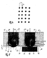
- the rolling elements are arranged at a distance a from one another. This Distance is essentially determined by the size of the rolling elements 13 to 22 and determines the required stability of the tool body 12.
- the rolling elements 13 to 22 are not consecutive but arranged from plane to plane as shown in FIG offset a lateral distance b.
- the tool body 12 is equipped with a clamping shaft 25, the forms the interface to the processing machine (not shown).
- the processing machine leads in the described tool 1 only one reciprocating, linear motion as shown in Figure 2 with the Arrow 26 is indicated to the workpiece 27 with its overall length 1 to to edit.
- Each rolling element 13 to 22 leaves a parallel to the Direction of movement 26 of the tool 1 directed track. With progression The machining therefore produces the tool 1 with its longitudinal movement 26 a plurality of tracks at a distance b.
- a sufficient number of Ball levels provided, the entire surface to be machined of the workpiece 27 occupied by tracks at a distance b and thus completely processed. If the tool 1 filled with double the length, one can For reasons of process reliability, desired double processing in a passage.
- FIG. 2 clearly shows that the rolling elements are at an angle to the longitudinal axis of the tool 1 extending lines are arranged. This results the offset b, which leads to a planar machining of the workpiece 27 leads.
- the same effect can also be achieved by the rolling elements are arranged on lines that are parallel to the longitudinal axis of the Tool extend when the tool is slightly oblique to the drawn Movement direction 26 is moved.
- the distance b can be arbitrary be varied to either the workpiece on close together arranged lines to edit and / or in one pass several times to revise.
- Figures 2 and 3 show that the tool length L is a multiple of Workpiece length is 1. This means that a high number of rolling elements not engaged, while only a small number at each Rolling works. With a tool according to the prior art Such an arrangement is not feasible because the non-engaged Rolling elements allow the hydraulic fluid to escape freely. This has in the out of the workpiece tool areas such a high fluid loss result that the existing for all rolling elements common pressure supply via the chamber 24 is insufficient would.
- rolling elements are 13, 14 stored so that they interact in the resting state obtained with the tool body 12 a valve function.
- the rolling elements 13, 14 are held in bores 28, 29 of the tool body 12 such that they are about the outer contour 30 of the tool body 12 to the Dimension e are exposed.
- Rolling elements 13 and 14 and bore 28 and 29, respectively are coordinated so that a minor circumferential Seal gap 31 or 32 is formed.
- the trained as a circumferential collar Valve seat 33 and 34 prevents falling out of the rolling element 13 or 14 from the tool body 12 and the peripheral collar 35 or 36 prevents the rolling elements 13 and 14 in the inner chamber 24th of the tool 1 fall into it.
- the rolling element 14 hits due to the linear movement 26 of the tool 1 on the workpiece 41, it is lifted by the workpiece 41 and the still existing hydraulic force in the bore 29th now presses the rolling elements 14 against the workpiece surface 42.
- the indicated by the arrow 40 force of the hydraulic fluid generated high compressive stresses in the workpiece surface 42, the plasticizing the boundary layer and the desired transformation of the same leads.
- the sealing gap 31 or 32 is dimensioned such that it acts as a hydraulic throttle acts and only a small amount of liquid, indicated by the arrow 43 is, escape from the pressure chamber. So on the one hand the required pressure for continuous generation of rolling force in the Preserved pressure chamber and on the other hand, the rolling element 14 can be practically rotate without friction in the bore 29. In this way, the rolling element 14 roll on the workpiece surface 42 until the workpiece end is reached and the rolling elements 14 due to the hydraulic force can emerge again in the rest position shown on the rolling elements 13.
- tool 50 is provided.
- This tool is the effective area 51 of the tool 50 not just but as a circular arc segment educated.
- the machining movement 52 does not take place linear but as a circle or circle segment movement. Thereby can arcuate surfaces on the workpiece 53 on the length 1 of the workpiece 53 are processed.
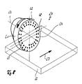
- FIG. 8 Another embodiment of a rolling tool is shown in FIG. 8.
- the tool body 61 corresponding to Arrow direction of the arrow 62 is rotated about the axis 63.
- the tool body 61 has a flat surface 64 on which a plurality of rolling elements 65 spiral are arranged.
- a dashed and transparent illustrated workpiece 66 is translational according to the direction of the arrow 67 guided along the tool, that the side surface 68 of the workpiece 66 as with a polishing pad by means of the workpiece 60 and in particular the rolling elements 65 is processed.
Landscapes
- Engineering & Computer Science (AREA)
- Mechanical Engineering (AREA)
- Rolling Contact Bearings (AREA)
- Machine Tool Units (AREA)
- Reduction Rolling/Reduction Stand/Operation Of Reduction Machine (AREA)
- Turning (AREA)
- Grinding And Polishing Of Tertiary Curved Surfaces And Surfaces With Complex Shapes (AREA)
- Finish Polishing, Edge Sharpening, And Grinding By Specific Grinding Devices (AREA)
- Rolls And Other Rotary Bodies (AREA)
Abstract
Description
- Figur 1
- einen Schnitt durch ein erfindungsgemäßes Werkzeug längst der in Figur 2 eingezeichneten Schnittlinie,
- Figur 2
- eine Draufsicht auf ein erfindungsgemäßes Werkzeug mit einem schematisch eingezeichneten Werkstück,
- Figur 3
- eine Seitenansicht des in Figur 2 gezeigten Werkzeugs,
- Figur 4
- eine schematische Darstellung eines Ausschnitts aus der in Figur 2 als Detail z gezeigten Einzelheit,
- Figur 5
- eine schematische Darstellung der Wirkweise der hydrostatischen Lager,
- Figur 6
- schematisch eine Seitenansicht eines bogenförmigen Werkzeugs,
- Figur 7
- eine Draufsicht auf das in Figur 6 gezeigte bogenförmige Werkzeug und
- Figur 8
- eine schematische Ansicht eines Werkzeugs mit einer im wesentlichen planen Ebene.
Claims (10)
- Verfahren zum Walzen eines Werkstücks (27) mit einem Walzwerkzeug (1) mit mehreren in hydrostatischen Lagern (2) angeordneten Wälzkörpern (13), dadurch gekennzeichnet, dass während des Walzens nur ein Teil der Wälzkörper (13) in Eingriff mit dem Werkstück (27) ist und die nicht mit dem Werkstück (27) in Eingriff stehenden Wälzkörper (13) das hydrostatische Lager (2) im wesentlichen abdichten.
- Verfahren nach Anspruch 1, dadurch gekennzeichnet, dass das Walzwerkzeug (1) linear oder rotatorisch bewegt wird.
- Verfahren nach Anspruch 1 oder 2, dadurch gekennzeichnet, dass bei einer linearen Bewegung des Walzwerkzeugs (1) in einer Richtung (26) mehr als dieselbe Stelle des Werkstücks (27) bearbeitet wird.
- Walzwerkzeug (1) mit mehreren in hydrostatischen Lagern (2) angeordneten Wälzkörpern 13, dadurch gekennzeichnet, dass die Wälzkörper (13) auf einer Fläche verteilt angeordnet sind.
- Walzwerkzeug nach Anspruch 4, dadurch gekennzeichnet, dass die Fläche in mindestens einer Richtung gebogen ausgebildet ist.
- Walzwerkzeug nach Anspruch 4 oder 5, dadurch gekennzeichnet, dass die Fläche in mindestens einer Richtung abgeknickt ausgebildet ist.
- Walzwerkzeug nach einem der Ansprüche 4 bis 6, dadurch gekennzeichnet, dass in Bearbeitungsrichtung (26) hintereinander angeordnete Wälzkörper (13) um eine Länge b versetzt angeordnet sind.
- Walzwerkzeug (1) mit mehreren in hydrostatischen Lagern (2) angeordneten Wälzkörpern (13), dadurch gekennzeichnet, dass die hydrostatischen Lager (2) im Bereich der Wälzkörper (13) jeweils eine umlaufende Dichtung (32) aufweisen.
- Walzwerkzeug (1) nach Anspruch 8, dadurch gekennzeichnet, dass die hydrostatischen Lager (2) einen Dichtspalt aufweisen, der derart bemessen ist, dass er als hydraulische Drossel wirkt.
- Anordnung aus einem Walzwerkzeug (1) mit mehreren in hydrostatischen Lagern (2) angeordneten Wälzkörpern (13) und einem Werkstück (39), dadurch gekennzeichnet, dass ein Teil der Wälzkörper (13) entsprechend dem Abstand zwischen hydrostatischem Lager und Werkstück (39) über das hydrostatische Lager (2) vorsteht und ein anderer Teil mehr als diesen Abstand über das hydrostatische Lager vorsteht.
Applications Claiming Priority (2)
| Application Number | Priority Date | Filing Date | Title |
|---|---|---|---|
| DE10133314 | 2001-07-12 | ||
| DE10133314A DE10133314A1 (de) | 2001-07-12 | 2001-07-12 | Verfahren und Werkzeug zum Walzen eines Werkstücks und Anordnung aus einem Walzwerkzeug und einem Werkstück |
Publications (3)
| Publication Number | Publication Date |
|---|---|
| EP1275472A2 true EP1275472A2 (de) | 2003-01-15 |
| EP1275472A3 EP1275472A3 (de) | 2004-02-11 |
| EP1275472B1 EP1275472B1 (de) | 2007-04-04 |
Family
ID=7691176
Family Applications (1)
| Application Number | Title | Priority Date | Filing Date |
|---|---|---|---|
| EP02009445A Expired - Lifetime EP1275472B1 (de) | 2001-07-12 | 2002-04-25 | Verfahren und Werkzeug zum Walzen eines Werkstücks und Anordnung aus einem Walzwerkzeug und einem Werkstück |
Country Status (7)
| Country | Link |
|---|---|
| US (1) | US6755065B2 (de) |
| EP (1) | EP1275472B1 (de) |
| KR (1) | KR20030007143A (de) |
| AT (1) | ATE358554T1 (de) |
| CA (1) | CA2393237A1 (de) |
| DE (2) | DE10133314A1 (de) |
| PL (1) | PL198740B1 (de) |
Cited By (6)
| Publication number | Priority date | Publication date | Assignee | Title |
|---|---|---|---|---|
| CZ302940B6 (cs) * | 2010-12-10 | 2012-01-18 | Comtes Fht A.S. | Zpusob mechanického zpevnování povrchu kovového polotovaru a zarízení k provádení tohoto zpusobu |
| WO2012107582A1 (de) * | 2011-02-10 | 2012-08-16 | Mauser-Werke Oberndorf Maschinenbau Gmbh | Walzwerkzeug |
| WO2012120181A3 (es) * | 2011-03-10 | 2012-11-01 | Universitat Politècnica De Catalunya | Herramienta con bola a baja presión, aplicable para bruñido de superficies |
| RU2493265C2 (ru) * | 2008-01-31 | 2013-09-20 | Дюмонт Свитзерлэнд Аг | Способ прокатки с применением одноцилиндрового толкаемого валка, устройство для его осуществления и изделия, изготовленные по данному способу |
| EP2759373A2 (de) | 2013-01-29 | 2014-07-30 | Zachodniopomorski Uniwersytet Technologiczny w Szczecinie | Verfahren zum Kontrollieren des Drucks eines hydrostatischen Glättwerkzeug und hydrostatisches Glättwerkzeug |
| US9321135B2 (en) | 2011-02-11 | 2016-04-26 | Ecoroll Ag Werkzeugtechnik | Fluidostatic rolling device for surface processing and method for shaping the edge layer |
Families Citing this family (7)
| Publication number | Priority date | Publication date | Assignee | Title |
|---|---|---|---|---|
| US7210209B2 (en) * | 2003-01-21 | 2007-05-01 | Seagate Technology Llc | System and method for ballizing and measuring a workpiece bore hole |
| GB0425088D0 (en) | 2004-11-13 | 2004-12-15 | Holset Engineering Co | Compressor wheel |
| US8024846B2 (en) * | 2006-01-27 | 2011-09-27 | General Electric Company | Preparation of an article surface having a surface compressive texture |
| US8393368B2 (en) * | 2009-06-01 | 2013-03-12 | Lockheed Martin Corporation | Numerically controlled composite compaction device |
| DE102010008694A1 (de) | 2009-07-21 | 2011-02-10 | Ferroll Gmbh | Vorrichtung zum Walzen eines exzentrischen Rotationsbauteils, Walzmaschine und Verfahren sowie exzentrisches Rotationsbauteil |
| DE102018114689A1 (de) * | 2018-06-19 | 2019-12-19 | Schaeffler Technologies AG & Co. KG | Walzkörper für ein hydrostatisches Walzwerkzeug und hydrostatisches Walzwerkzeug mit dem Walzkörper |
| DE102018132771A1 (de) * | 2018-12-19 | 2020-06-25 | Schaeffler Technologies AG & Co. KG | Verfahren zur Oberflächenbehandlung, Wälzlagerbauteil und Vorrichtung |
Family Cites Families (17)
| Publication number | Priority date | Publication date | Assignee | Title |
|---|---|---|---|---|
| FR864956A (fr) * | 1939-12-29 | 1941-05-09 | Dispositif mécanique pour le polissage ou le brunissage d'objets métalliques ou autres | |
| US2575938A (en) * | 1949-11-22 | 1951-11-20 | Perfect Circle Corp | Tool for expanding cylinder liners |
| US3201827A (en) * | 1963-04-08 | 1965-08-24 | Anaconda Wire & Cable Co | Tube-stretching mandrel |
| US3911707A (en) * | 1974-10-08 | 1975-10-14 | Anatoly Petrovich Minakov | Finishing tool |
| US3934443A (en) * | 1975-01-03 | 1976-01-27 | Keen David P | Peening tool |
| DE2521014C3 (de) * | 1975-05-12 | 1980-11-13 | Mogilevskij Avtomobilnjy Zavod Imeni S.M. Kirova, Mogilew (Sowjetunion) | Impulsstoßwerkzeug zur Schlichtbearbeitung von inneren Rotationsflächen von Werkstücken |
| DE3823675A1 (de) * | 1988-07-13 | 1990-01-18 | Dornier Gmbh | Einrichtung zum biegeumformen oder richten von werkstuecken durch plastische formaenderung |
| DE8809823U1 (de) * | 1988-08-02 | 1988-10-06 | Wilhelm Hegenscheidt Gmbh, 5140 Erkelenz | Walzwerkzeug |
| DE4015205C1 (en) * | 1990-05-11 | 1991-08-22 | Mtu Muenchen Gmbh | Method of reinforcing gas turbine rotor - has balls forced against base surface of slot in rotor to compress it |
| FR2670410B1 (fr) * | 1990-12-14 | 1995-02-24 | Cleciml | Installation de laminage de produits plats. |
| GB9210292D0 (en) * | 1992-05-13 | 1992-07-01 | British Steel Plc | Methods and apparatus for effecting domain refinement of electrical steels |
| DE19516834A1 (de) * | 1995-05-08 | 1996-11-14 | Siemens Ag | Walzvorrichtung zur Erzeugung von Druckeigenspannungen in einem Bauteil sowie Verwendung der Walzvorrichtung |
| DE19534631A1 (de) * | 1995-09-19 | 1997-03-20 | Hegenscheidt Werkzeugtechnik G | Verfahren und Vorrichtung zum Bearbeiten einer Werkstückoberfläche mit einem in einem hydrostatischen Lager gelagerten Walzkörper |
| US5826453A (en) | 1996-12-05 | 1998-10-27 | Lambda Research, Inc. | Burnishing method and apparatus for providing a layer of compressive residual stress in the surface of a workpiece |
| JP3283823B2 (ja) * | 1998-06-02 | 2002-05-20 | 株式会社日立製作所 | 板材圧延機 |
| IT1302573B1 (it) * | 1998-10-01 | 2000-09-29 | Orazio Bagnasco | Macchina per comminuzione, impastamento. trattamento in genere dimateriali mediante loro alimentazione centrifuga, continua, verso un |
| JP3750974B2 (ja) | 1999-05-06 | 2006-03-01 | 株式会社スギノマシン | 切削とローラバニシング仕上げを行う複合工具 |
-
2001
- 2001-07-12 DE DE10133314A patent/DE10133314A1/de not_active Ceased
-
2002
- 2002-04-25 DE DE50209856T patent/DE50209856D1/de not_active Expired - Lifetime
- 2002-04-25 EP EP02009445A patent/EP1275472B1/de not_active Expired - Lifetime
- 2002-04-25 AT AT02009445T patent/ATE358554T1/de not_active IP Right Cessation
- 2002-06-25 US US10/179,363 patent/US6755065B2/en not_active Expired - Lifetime
- 2002-07-04 PL PL354890A patent/PL198740B1/pl unknown
- 2002-07-12 CA CA002393237A patent/CA2393237A1/en not_active Abandoned
- 2002-07-12 KR KR1020020040562A patent/KR20030007143A/ko not_active Withdrawn
Cited By (9)
| Publication number | Priority date | Publication date | Assignee | Title |
|---|---|---|---|---|
| RU2493265C2 (ru) * | 2008-01-31 | 2013-09-20 | Дюмонт Свитзерлэнд Аг | Способ прокатки с применением одноцилиндрового толкаемого валка, устройство для его осуществления и изделия, изготовленные по данному способу |
| CZ302940B6 (cs) * | 2010-12-10 | 2012-01-18 | Comtes Fht A.S. | Zpusob mechanického zpevnování povrchu kovového polotovaru a zarízení k provádení tohoto zpusobu |
| WO2012107582A1 (de) * | 2011-02-10 | 2012-08-16 | Mauser-Werke Oberndorf Maschinenbau Gmbh | Walzwerkzeug |
| CN103442848A (zh) * | 2011-02-10 | 2013-12-11 | 毛瑟-韦尔克奥伯恩多夫机械制造有限公司 | 滚压工具 |
| CN103442848B (zh) * | 2011-02-10 | 2016-09-28 | 毛瑟-韦尔克奥伯恩多夫机械制造有限公司 | 滚压工具 |
| US9321135B2 (en) | 2011-02-11 | 2016-04-26 | Ecoroll Ag Werkzeugtechnik | Fluidostatic rolling device for surface processing and method for shaping the edge layer |
| WO2012120181A3 (es) * | 2011-03-10 | 2012-11-01 | Universitat Politècnica De Catalunya | Herramienta con bola a baja presión, aplicable para bruñido de superficies |
| ES2393145A1 (es) * | 2011-03-10 | 2012-12-18 | Universitat Politècnica De Catalunya | Herramienta con bola a baja presión, aplicable para bruñido de superficies. |
| EP2759373A2 (de) | 2013-01-29 | 2014-07-30 | Zachodniopomorski Uniwersytet Technologiczny w Szczecinie | Verfahren zum Kontrollieren des Drucks eines hydrostatischen Glättwerkzeug und hydrostatisches Glättwerkzeug |
Also Published As
| Publication number | Publication date |
|---|---|
| US6755065B2 (en) | 2004-06-29 |
| DE10133314A1 (de) | 2003-01-23 |
| DE50209856D1 (de) | 2007-05-16 |
| CA2393237A1 (en) | 2003-01-12 |
| EP1275472B1 (de) | 2007-04-04 |
| KR20030007143A (ko) | 2003-01-23 |
| EP1275472A3 (de) | 2004-02-11 |
| PL354890A1 (en) | 2003-01-13 |
| PL198740B1 (pl) | 2008-07-31 |
| US20030010080A1 (en) | 2003-01-16 |
| ATE358554T1 (de) | 2007-04-15 |
Similar Documents
| Publication | Publication Date | Title |
|---|---|---|
| EP1275472B1 (de) | Verfahren und Werkzeug zum Walzen eines Werkstücks und Anordnung aus einem Walzwerkzeug und einem Werkstück | |
| DD283966A5 (de) | Walzwerkzeug | |
| DE4321800C2 (de) | Ventiltelleranordnung für ein Rückschlagventil | |
| DE2811528A1 (de) | Kolben und kolbenring fuer kolbenmaschinen, insbesondere brennkraftmaschinen | |
| DE2364256A1 (de) | Druckmittelbetaetigte dichtung | |
| DE102011050662A1 (de) | Walzmaschine | |
| DE10353260A1 (de) | Lagermontageflansch mit flexibler Tasche | |
| DE2948391C2 (de) | ||
| DE602006000039T2 (de) | Ventil, Pumpenanordnung und Verfahren zur Ventilherstellung | |
| DE2515229A1 (de) | Pumpe, z.b. kolbenpumpe fuer hydraulische duesenwebstuehle, pumpe mit rotationsteilen zur foerderung von fluessigkeiten und dergleichen | |
| EP0039418B1 (de) | Pressluftbetätigte Schmierpresse | |
| EP3077656B1 (de) | Kraftstoffpumpe | |
| DE102010024907A1 (de) | Linearstellglied | |
| DE1956551A1 (de) | Presswerkzeug fuer die Herstellung von Stangen und Rohren durch Pressen von Pulver | |
| DE102005051276B4 (de) | Rollenlager und Pumpe mit einem Rollenlager | |
| DE10340267A1 (de) | Walzwerkzeug und Walzrolle zum Walzen, insbesondere Festwalzen, eines Werkstücks | |
| DE102017102094B4 (de) | Werkzeugmodul zur Feinbearbeitung | |
| DE931865C (de) | Gleitlager mit kippbaren Bloecken | |
| DE1902804A1 (de) | Lager | |
| CH628548A5 (en) | Method for manufacturing a sintered product having at least one cavity, and sintered product manufactured according to this method | |
| DE2201817C2 (de) | Druckmittelbetätigtes Hubventil | |
| EP3178581B1 (de) | Hydraulischer hochfrequenzzylinder | |
| DE847849C (de) | Kolbenpumpe | |
| AT233339B (de) | Ringförmige Dichtungsanordnung | |
| DE2746825A1 (de) | Achslageranordnung |
Legal Events
| Date | Code | Title | Description |
|---|---|---|---|
| PUAI | Public reference made under article 153(3) epc to a published international application that has entered the european phase |
Free format text: ORIGINAL CODE: 0009012 |
|
| AK | Designated contracting states |
Kind code of ref document: A2 Designated state(s): AT BE CH CY DE DK ES FI FR GB GR IE IT LI LU MC NL PT SE TR |
|
| AX | Request for extension of the european patent |
Free format text: AL;LT;LV;MK;RO;SI |
|
| PUAL | Search report despatched |
Free format text: ORIGINAL CODE: 0009013 |
|
| AK | Designated contracting states |
Kind code of ref document: A3 Designated state(s): AT BE CH CY DE DK ES FI FR GB GR IE IT LI LU MC NL PT SE TR |
|
| AX | Request for extension of the european patent |
Extension state: AL LT LV MK RO SI |
|
| RIC1 | Information provided on ipc code assigned before grant |
Ipc: 7B 24B 39/00 B Ipc: 7B 24B 39/06 A |
|
| 17P | Request for examination filed |
Effective date: 20040728 |
|
| AKX | Designation fees paid |
Designated state(s): AT BE CH CY DE DK ES FI FR GB GR IE IT LI LU MC NL PT SE TR |
|
| 17Q | First examination report despatched |
Effective date: 20041006 |
|
| 17Q | First examination report despatched |
Effective date: 20041006 |
|
| GRAP | Despatch of communication of intention to grant a patent |
Free format text: ORIGINAL CODE: EPIDOSNIGR1 |
|
| GRAS | Grant fee paid |
Free format text: ORIGINAL CODE: EPIDOSNIGR3 |
|
| GRAA | (expected) grant |
Free format text: ORIGINAL CODE: 0009210 |
|
| AK | Designated contracting states |
Kind code of ref document: B1 Designated state(s): AT BE CH CY DE DK ES FI FR GB GR IE IT LI LU MC NL PT SE TR |
|
| PG25 | Lapsed in a contracting state [announced via postgrant information from national office to epo] |
Ref country code: FI Free format text: LAPSE BECAUSE OF FAILURE TO SUBMIT A TRANSLATION OF THE DESCRIPTION OR TO PAY THE FEE WITHIN THE PRESCRIBED TIME-LIMIT Effective date: 20070404 |
|
| REG | Reference to a national code |
Ref country code: GB Ref legal event code: FG4D Free format text: NOT ENGLISH |
|
| REG | Reference to a national code |
Ref country code: CH Ref legal event code: EP |
|
| REF | Corresponds to: |
Ref document number: 50209856 Country of ref document: DE Date of ref document: 20070516 Kind code of ref document: P |
|
| REG | Reference to a national code |
Ref country code: IE Ref legal event code: FG4D Free format text: LANGUAGE OF EP DOCUMENT: GERMAN |
|
| PG25 | Lapsed in a contracting state [announced via postgrant information from national office to epo] |
Ref country code: SE Free format text: LAPSE BECAUSE OF FAILURE TO SUBMIT A TRANSLATION OF THE DESCRIPTION OR TO PAY THE FEE WITHIN THE PRESCRIBED TIME-LIMIT Effective date: 20070704 |
|
| PG25 | Lapsed in a contracting state [announced via postgrant information from national office to epo] |
Ref country code: ES Free format text: LAPSE BECAUSE OF FAILURE TO SUBMIT A TRANSLATION OF THE DESCRIPTION OR TO PAY THE FEE WITHIN THE PRESCRIBED TIME-LIMIT Effective date: 20070715 |
|
| REG | Reference to a national code |
Ref country code: CH Ref legal event code: NV Representative=s name: E. BLUM & CO. AG PATENT- UND MARKENANWAELTE VSP |
|
| PG25 | Lapsed in a contracting state [announced via postgrant information from national office to epo] |
Ref country code: PT Free format text: LAPSE BECAUSE OF FAILURE TO SUBMIT A TRANSLATION OF THE DESCRIPTION OR TO PAY THE FEE WITHIN THE PRESCRIBED TIME-LIMIT Effective date: 20070904 |
|
| ET | Fr: translation filed | ||
| NLV1 | Nl: lapsed or annulled due to failure to fulfill the requirements of art. 29p and 29m of the patents act | ||
| GBV | Gb: ep patent (uk) treated as always having been void in accordance with gb section 77(7)/1977 [no translation filed] |
Effective date: 20070404 |
|
| REG | Reference to a national code |
Ref country code: IE Ref legal event code: FD4D |
|
| BERE | Be: lapsed |
Owner name: ECOROLL AG, WERKZEUGTECHNIK Effective date: 20070430 |
|
| PG25 | Lapsed in a contracting state [announced via postgrant information from national office to epo] |
Ref country code: IE Free format text: LAPSE BECAUSE OF FAILURE TO SUBMIT A TRANSLATION OF THE DESCRIPTION OR TO PAY THE FEE WITHIN THE PRESCRIBED TIME-LIMIT Effective date: 20070404 Ref country code: NL Free format text: LAPSE BECAUSE OF FAILURE TO SUBMIT A TRANSLATION OF THE DESCRIPTION OR TO PAY THE FEE WITHIN THE PRESCRIBED TIME-LIMIT Effective date: 20070404 Ref country code: DK Free format text: LAPSE BECAUSE OF FAILURE TO SUBMIT A TRANSLATION OF THE DESCRIPTION OR TO PAY THE FEE WITHIN THE PRESCRIBED TIME-LIMIT Effective date: 20070404 |
|
| PLBE | No opposition filed within time limit |
Free format text: ORIGINAL CODE: 0009261 |
|
| STAA | Information on the status of an ep patent application or granted ep patent |
Free format text: STATUS: NO OPPOSITION FILED WITHIN TIME LIMIT |
|
| 26N | No opposition filed |
Effective date: 20080107 |
|
| PG25 | Lapsed in a contracting state [announced via postgrant information from national office to epo] |
Ref country code: BE Free format text: LAPSE BECAUSE OF NON-PAYMENT OF DUE FEES Effective date: 20070430 |
|
| PG25 | Lapsed in a contracting state [announced via postgrant information from national office to epo] |
Ref country code: GB Free format text: LAPSE BECAUSE OF FAILURE TO SUBMIT A TRANSLATION OF THE DESCRIPTION OR TO PAY THE FEE WITHIN THE PRESCRIBED TIME-LIMIT Effective date: 20070404 Ref country code: GR Free format text: LAPSE BECAUSE OF FAILURE TO SUBMIT A TRANSLATION OF THE DESCRIPTION OR TO PAY THE FEE WITHIN THE PRESCRIBED TIME-LIMIT Effective date: 20070705 |
|
| PG25 | Lapsed in a contracting state [announced via postgrant information from national office to epo] |
Ref country code: AT Free format text: LAPSE BECAUSE OF NON-PAYMENT OF DUE FEES Effective date: 20070425 |
|
| PG25 | Lapsed in a contracting state [announced via postgrant information from national office to epo] |
Ref country code: MC Free format text: LAPSE BECAUSE OF NON-PAYMENT OF DUE FEES Effective date: 20070430 |
|
| PG25 | Lapsed in a contracting state [announced via postgrant information from national office to epo] |
Ref country code: CY Free format text: LAPSE BECAUSE OF FAILURE TO SUBMIT A TRANSLATION OF THE DESCRIPTION OR TO PAY THE FEE WITHIN THE PRESCRIBED TIME-LIMIT Effective date: 20070404 |
|
| PG25 | Lapsed in a contracting state [announced via postgrant information from national office to epo] |
Ref country code: LU Free format text: LAPSE BECAUSE OF NON-PAYMENT OF DUE FEES Effective date: 20070425 |
|
| PG25 | Lapsed in a contracting state [announced via postgrant information from national office to epo] |
Ref country code: TR Free format text: LAPSE BECAUSE OF FAILURE TO SUBMIT A TRANSLATION OF THE DESCRIPTION OR TO PAY THE FEE WITHIN THE PRESCRIBED TIME-LIMIT Effective date: 20070404 |
|
| REG | Reference to a national code |
Ref country code: DE Ref legal event code: R082 Ref document number: 50209856 Country of ref document: DE Representative=s name: SCHIEBER - FARAGO, DE Ref country code: DE Ref legal event code: R082 Ref document number: 50209856 Country of ref document: DE Representative=s name: FARAGO PATENTANWAELTE, DE Ref country code: DE Ref legal event code: R082 Ref document number: 50209856 Country of ref document: DE Representative=s name: FARAGO PATENTANWALTS- UND RECHTSANWALTSGESELLS, DE |
|
| REG | Reference to a national code |
Ref country code: FR Ref legal event code: PLFP Year of fee payment: 15 |
|
| REG | Reference to a national code |
Ref country code: FR Ref legal event code: PLFP Year of fee payment: 16 |
|
| REG | Reference to a national code |
Ref country code: FR Ref legal event code: PLFP Year of fee payment: 17 |
|
| PGFP | Annual fee paid to national office [announced via postgrant information from national office to epo] |
Ref country code: DE Payment date: 20210430 Year of fee payment: 20 Ref country code: FR Payment date: 20210423 Year of fee payment: 20 Ref country code: IT Payment date: 20210427 Year of fee payment: 20 |
|
| PGFP | Annual fee paid to national office [announced via postgrant information from national office to epo] |
Ref country code: CH Payment date: 20210420 Year of fee payment: 20 |
|
| REG | Reference to a national code |
Ref country code: DE Ref legal event code: R071 Ref document number: 50209856 Country of ref document: DE |
|
| REG | Reference to a national code |
Ref country code: CH Ref legal event code: PL |