EP1275478A1 - Vorrichtung zum Schneiden biegeweicher, flächiger Werkstücke - Google Patents
Vorrichtung zum Schneiden biegeweicher, flächiger Werkstücke Download PDFInfo
- Publication number
- EP1275478A1 EP1275478A1 EP02450140A EP02450140A EP1275478A1 EP 1275478 A1 EP1275478 A1 EP 1275478A1 EP 02450140 A EP02450140 A EP 02450140A EP 02450140 A EP02450140 A EP 02450140A EP 1275478 A1 EP1275478 A1 EP 1275478A1
- Authority
- EP
- European Patent Office
- Prior art keywords
- pressure roller
- pressure
- workpiece
- cutting
- pressure rollers
- Prior art date
- Legal status (The legal status is an assumption and is not a legal conclusion. Google has not performed a legal analysis and makes no representation as to the accuracy of the status listed.)
- Granted
Links
- 238000005520 cutting process Methods 0.000 title claims abstract description 39
- 239000000463 material Substances 0.000 title description 2
- 238000005096 rolling process Methods 0.000 claims abstract description 19
- 238000010438 heat treatment Methods 0.000 claims description 2
- 230000006835 compression Effects 0.000 description 3
- 238000007906 compression Methods 0.000 description 3
- 230000000694 effects Effects 0.000 description 2
- 230000002349 favourable effect Effects 0.000 description 2
- 230000002093 peripheral effect Effects 0.000 description 2
- 238000005452 bending Methods 0.000 description 1
- 230000009286 beneficial effect Effects 0.000 description 1
- 238000010276 construction Methods 0.000 description 1
- 238000006073 displacement reaction Methods 0.000 description 1
- 239000000835 fiber Substances 0.000 description 1
- 239000002657 fibrous material Substances 0.000 description 1
- 230000001771 impaired effect Effects 0.000 description 1
- 239000010985 leather Substances 0.000 description 1
- 238000002844 melting Methods 0.000 description 1
- 230000008018 melting Effects 0.000 description 1
- 238000003825 pressing Methods 0.000 description 1
- 238000003860 storage Methods 0.000 description 1
- 230000037303 wrinkles Effects 0.000 description 1
Images


Classifications
-
- B—PERFORMING OPERATIONS; TRANSPORTING
- B26—HAND CUTTING TOOLS; CUTTING; SEVERING
- B26F—PERFORATING; PUNCHING; CUTTING-OUT; STAMPING-OUT; SEVERING BY MEANS OTHER THAN CUTTING
- B26F1/00—Perforating; Punching; Cutting-out; Stamping-out; Apparatus therefor
- B26F1/38—Cutting-out; Stamping-out
- B26F1/3806—Cutting-out; Stamping-out wherein relative movements of tool head and work during cutting have a component tangential to the work surface
-
- B—PERFORMING OPERATIONS; TRANSPORTING
- B26—HAND CUTTING TOOLS; CUTTING; SEVERING
- B26D—CUTTING; DETAILS COMMON TO MACHINES FOR PERFORATING, PUNCHING, CUTTING-OUT, STAMPING-OUT OR SEVERING
- B26D7/00—Details of apparatus for cutting, cutting-out, stamping-out, punching, perforating, or severing by means other than cutting
- B26D7/01—Means for holding or positioning work
- B26D7/02—Means for holding or positioning work with clamping means
- B26D7/025—Means for holding or positioning work with clamping means acting upon planar surfaces
-
- Y—GENERAL TAGGING OF NEW TECHNOLOGICAL DEVELOPMENTS; GENERAL TAGGING OF CROSS-SECTIONAL TECHNOLOGIES SPANNING OVER SEVERAL SECTIONS OF THE IPC; TECHNICAL SUBJECTS COVERED BY FORMER USPC CROSS-REFERENCE ART COLLECTIONS [XRACs] AND DIGESTS
- Y10—TECHNICAL SUBJECTS COVERED BY FORMER USPC
- Y10T—TECHNICAL SUBJECTS COVERED BY FORMER US CLASSIFICATION
- Y10T225/00—Severing by tearing or breaking
- Y10T225/30—Breaking or tearing apparatus
- Y10T225/307—Combined with preliminary weakener or with nonbreaking cutter
- Y10T225/321—Preliminary weakener
-
- Y—GENERAL TAGGING OF NEW TECHNOLOGICAL DEVELOPMENTS; GENERAL TAGGING OF CROSS-SECTIONAL TECHNOLOGIES SPANNING OVER SEVERAL SECTIONS OF THE IPC; TECHNICAL SUBJECTS COVERED BY FORMER USPC CROSS-REFERENCE ART COLLECTIONS [XRACs] AND DIGESTS
- Y10—TECHNICAL SUBJECTS COVERED BY FORMER USPC
- Y10T—TECHNICAL SUBJECTS COVERED BY FORMER US CLASSIFICATION
- Y10T83/00—Cutting
- Y10T83/323—With means to stretch work temporarily
-
- Y—GENERAL TAGGING OF NEW TECHNOLOGICAL DEVELOPMENTS; GENERAL TAGGING OF CROSS-SECTIONAL TECHNOLOGIES SPANNING OVER SEVERAL SECTIONS OF THE IPC; TECHNICAL SUBJECTS COVERED BY FORMER USPC CROSS-REFERENCE ART COLLECTIONS [XRACs] AND DIGESTS
- Y10—TECHNICAL SUBJECTS COVERED BY FORMER USPC
- Y10T—TECHNICAL SUBJECTS COVERED BY FORMER US CLASSIFICATION
- Y10T83/00—Cutting
- Y10T83/748—With work immobilizer
- Y10T83/7587—Gapped work-constrainer
Definitions
- the invention relates to a device for cutting flexible, flat workpieces with a workpiece support, one to the workpiece support adjustable, at least one knife having cutter head and with a knife head associated, laterally next to the knife provided and this opposite to the workpiece support adjustable Stripper plate.
- a cutter head with at least one Inserting a knife the workpiece receiving on a workpiece support is adjustable and relative to the workpiece support along a predetermined Cutting process is performed.
- the correct position of the workpiece on the workpiece support is assigned by a cutter head Sliding shoe, which not only the workpiece against the workpiece support holds, but also for keeping a predetermined Cutting depth ensures that by moving the shoe against the Knife can be adjusted perpendicular to the workpiece support.
- the invention is therefore based on the object, a device for Cutting bending soft, flat workpieces of the type described in such a way that one of the respective material of the workpiece largely independent, accurate cutting enabling bracket of the workpiece on the workpiece support can be ensured without To fear damage to the workpiece surface.
- the invention solves the problem set by the fact that the hold-down from at least one pressure roller forming a conical rolling surface with a transverse to the cutting direction, inclined relative to the workpiece support Axis exists.
- At least one pressure roller as a hold-down can first a sliding movement between the hold-down and the workpiece be avoided, whereby the due to such a sliding movement at a Sliding occurring difficulties are prevented.
- the due the conical rolling surface different peripheral speeds of Pressure rollers have no practical significance in this context.
- the conical rolling surface conditional inclination of the pressure roller axis is required to hold the hold down in the smallest possible lateral distance to be able to start from the knife to the workpiece. Because of the rolling the conical rolling surface of the pressure roller on the workpiece surface in the immediate Near the knife engagement the workpiece in the area of the knife engagement is kept pressed cut to the workpiece support, is Such workpiece holder for workpieces made of different workpieces equally suitable.
- the pressure roller can be pot-like be formed, wherein the pot wall open towards the knife the Rolling surface forms.
- This cup-like design of the pressure roller allows a partial Recording the cutter head in the pot area of the pressure roller, so that the Pressure roller near the knife can be placed on the workpiece.
- the inventive Pressure rollers are used advantageously. It's just a heater for the pressure roller or the pressure rollers at least in the area of Rolling surface to provide over the rolling surfaces, the heat transfer to the to ensure thermally treated cutting edge area.
- the storage of the pressure roller or pressure roller pair can be different Be solved constructive way.
- a Housing which can be connected from one to the cutter head Support ring and a bearing ring in the support ring against spring force axially displaceable bearing ring for receiving the pressure roller or pressure rollers.
- On the Support ring is the housing for the pressure roller or the pressure rollers coaxial with Knife head attached to this, so that upon rotation of the cutter head for knife guidance along a given cutting process the respective Pressure roller is taken and their required for the workpiece holder spatial assignment to the knife maintains.
- the bearing ring relative to the support ring is the respective pressure load of the workpiece predetermined by the pressure rollers.
- a workpiece support 2 usually a cutting table, provided, opposite to a cutter head 3 along a predetermined cutting process can be moved.
- This knife head 3 is provided with at least one blade 4, which is suitable for cutting Grooves or bevels as a peeling knife or for cutting the workpiece 1 may be formed as a separating knife.
- New compared to conventional Knife heads 3 is the intended hold-down for cutting fair Pressing the workpiece 1 to the workpiece support 2 in the form of two pressure rollers 5, whose axes 6 extend transversely to the cutting direction and are inclined relative to the workpiece support 2.
- the axes 6 of the pressure rollers 5 are held in a bearing ring 7 of a housing 8, in addition to the bearing ring 7 comprises a connectable to the cutter head 3 support ring 9.
- the Housing 8 is thus coaxial with the axis of rotation 10 of the cutter head 3 at this attached, so that the pressure rollers 5 to the knife guide along the predetermined cutting process required rotational movements about the axis of rotation Join in 10
- the bearing ring 7 is guided axially displaceably within the support ring 9, with the help of engaging in axial slots 11 of the bearing ring 7 Guide pin 12.
- the bearing ring 7 is thereby by compression springs 13 held in a stop position from which the bearing ring 7 in the housing. 8 can be inserted.
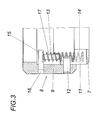
- the in a receiving bore 14 on the bearing ring. 7 supported compression springs 13 find their other abutment in pressure plates 15, which are inserted in circumferential slots 16 of the support ring 9 and axial bolts 17 to guide the springs 13 wear.
- the pressure rollers 5, which rotate freely in the illustrated embodiment are stored, but also via controlled drives depending on the respective Intersection can be driven, roll under exercise a corresponding pressure force over conical rolling surfaces 18 on the workpiece 1, which is about this pressure load immediately to the side of the Knife 4 is cut down to the correct level on the workpiece support 2.
- the pressure rollers are the fifth cup-shaped, wherein the pot wall 19 of the against the knife 4 out opening pots form the rolling surfaces 18.
- the pressure rollers 5 could at least be heated in the region of the rolling surfaces 18, about the pressure rollers. 5 to suspend the cut edges of a heat treatment.
- the Contact pressure of the pressure rollers 5 to the workpiece 1 via a control device be controlled according to the respective requirements. The mechanical Prerequisites for this are yes by the axial displacement of the bearing ring 7 in the housing 8 given.
Landscapes
- Life Sciences & Earth Sciences (AREA)
- Forests & Forestry (AREA)
- Engineering & Computer Science (AREA)
- Mechanical Engineering (AREA)
- Details Of Cutting Devices (AREA)
- Perforating, Stamping-Out Or Severing By Means Other Than Cutting (AREA)
- Finish Polishing, Edge Sharpening, And Grinding By Specific Grinding Devices (AREA)
- Auxiliary Devices For And Details Of Packaging Control (AREA)
- Nonmetal Cutting Devices (AREA)
- Treatment Of Fiber Materials (AREA)
Abstract
Description
- Fig. 1
- eine erfindungsgemäße Vorrichtung zum Schneiden biegeweicher, flächiger Werkstücke in einem vereinfachten Axialschnitt senkrecht zur Schnittrichtung,
- Fig. 2
- eine zum Teil aufgerissene Draufsicht auf das die Druckrollen aufnehmende Gehäuse und
- Fig. 3
- einen Schnitt nach der Linie Ill-lll der Fig. 2.
Claims (8)
- Vorrichtung zum Schneiden biegeweicher, flächiger Werkstücke (1) mit einer Werkstückauflage (2), einem an die Werkstückauflage (2) anstellbaren, wenigstens ein Messer (4) aufweisenden Messerkopf (3) und mit einem dem Messerkopf (3) zugeordneten, seitlich neben dem Messer (4) vorgesehenen und diesem gegenüber senkrecht zur Werkstückauflage (2) verstellbaren Niederhalter, dadurch gekennzeichnet, daß der Niederhalter aus zumindest einer eine konische Rollfläche (18) bildenden Druckrolle (5) mit einer quer zur Schnittrichtung verlaufenden, gegenüber der Werkstückauflage (2) geneigten Achse (6) besteht.
- Vorrichtung nach Anspruch 1, dadurch gekennzeichnet, daß die Druckrolle (5) topfartig ausgebildet ist, wobei die gegen das Messer (4) hin offene Topfwand (19) die Rollfläche (18) bildet.
- Vorrichtung nach Anspruch 1 oder 2, dadurch gekennzeichnet daß zwei Druckrollen (5) symmetrisch zu einer in Schnittrichtung verlaufenden, zur Werkstückauflage (2) senkrechten Ebene angeordnet sind.
- Vorrichtung nach einem der Ansprüche 1 bis 3, dadurch gekennzeichnet, daß ein Antrieb für die Druckrolle bzw. die Druckrollen (5) vorgesehen ist.
- Vorrichtung nach einem der Ansprüche 1 bis 4, dadurch gekennzeichnet, daß der Antrieb für die jeweilige Druckrolle (5) in Abhängigkeit vom Schnittverlauf ansteuerbar ist.
- Vorrichtung nach einem der Ansprüche 1 bis 5, dadurch gekennzeichnet, daß eine Steuereinrichtung für den Anpreßdruck der Druckrolle bzw. der Druckrollen (5) vorgesehen ist.
- Vorrichtung nach einem der Ansprüche 1 bis 6, dadurch gekennzeichnet, daß eine Heizeinrichtung für die Druckrolle bzw. die Druckrollen (5) zumindest im Bereich der Rollfläche (18) vorgesehen ist.
- Vorrichtung nach einem der Ansprüche 1 bis 7, dadurch gekennzeichnet, daß für die Druckrolle bzw. die Druckrollen (5) ein Gehäuse (8) vorgesehen ist, das aus einem an den Messerkopf (3) anschließbaren Tragring (9) und einem im Tragring (9) gegen Federkraft axial verschiebbaren Lagerring (7) zur Aufnahme der Druckrolle bzw. der Druckrollen (5) besteht.
Priority Applications (1)
| Application Number | Priority Date | Filing Date | Title |
|---|---|---|---|
| AT02450140T ATE280017T1 (de) | 2001-07-10 | 2002-06-25 | Vorrichtung zum schneiden biegeweicher, flächiger werkstücke |
Applications Claiming Priority (2)
| Application Number | Priority Date | Filing Date | Title |
|---|---|---|---|
| AT10722001 | 2001-07-10 | ||
| AT0107201A AT410526B (de) | 2001-07-10 | 2001-07-10 | Vorrichtung zum schneiden biegeweicher, flächiger werkstücke |
Publications (2)
| Publication Number | Publication Date |
|---|---|
| EP1275478A1 true EP1275478A1 (de) | 2003-01-15 |
| EP1275478B1 EP1275478B1 (de) | 2004-10-20 |
Family
ID=3684997
Family Applications (1)
| Application Number | Title | Priority Date | Filing Date |
|---|---|---|---|
| EP02450140A Expired - Lifetime EP1275478B1 (de) | 2001-07-10 | 2002-06-25 | Vorrichtung zum Schneiden biegeweicher, flächiger Werkstücke |
Country Status (5)
| Country | Link |
|---|---|
| US (1) | US20030010802A1 (de) |
| EP (1) | EP1275478B1 (de) |
| AT (2) | AT410526B (de) |
| DE (1) | DE50201335D1 (de) |
| ES (1) | ES2231664T3 (de) |
Families Citing this family (18)
| Publication number | Priority date | Publication date | Assignee | Title |
|---|---|---|---|---|
| US7291173B2 (en) | 2003-05-06 | 2007-11-06 | Aesculap Ii, Inc. | Artificial intervertebral disc |
| US20050143824A1 (en) * | 2003-05-06 | 2005-06-30 | Marc Richelsoph | Artificial intervertebral disc |
| DE102004028967B4 (de) * | 2004-06-16 | 2006-05-24 | Aesculap Ag & Co. Kg | Zwischenwirbelimplantat |
| EP2113151A1 (de) * | 2007-09-20 | 2009-11-04 | Hewlett-Packard Development Company, L.P. | Backbone für einen globalen kommunikationsring |
| ES2395504T3 (es) | 2009-05-02 | 2013-02-13 | Maschinenbau U. Konstruktion Gmbh Elmshorn | Dispositivo y procedimiento para cortar material de tela tejido y no tejido en forma de lámina o en forma de tira que permite el paso del aire |
| JP4756088B2 (ja) * | 2009-09-30 | 2011-08-24 | 株式会社ミドリテクノパーク | 皮革溝形成装置および皮革溝形成方法 |
| WO2012057795A1 (en) | 2010-10-29 | 2012-05-03 | Michelin Recherche Et Technique S.A. | Flexible guide for tire repair |
| US9266293B2 (en) | 2010-10-30 | 2016-02-23 | Michelin Recherche Et Technique S.A. | Depth marking tool for tire repair |
| WO2012074517A1 (en) | 2010-11-30 | 2012-06-07 | Michelin Recherche Et Technique S.A. | Profiled plane abrading tool for tire repairs |
| US9352438B2 (en) | 2011-03-31 | 2016-05-31 | Compagnie Generale Des Etablissements Michelin | Balanced abrading tool and methods for abrading |
| CN103008778A (zh) * | 2011-09-28 | 2013-04-03 | 上海双明光学科技有限公司 | 一种抛光皮用开槽设备 |
| FR2993197B1 (fr) * | 2012-07-11 | 2015-02-13 | Saint Gobain | Dispositif et procede de decoupe de matiere plastique en particulier d’un vitrage feuillete |
| DE102015201036B4 (de) * | 2015-01-22 | 2025-08-07 | Bayerische Motoren Werke Aktiengesellschaft | Portal mit einer Schneidevorrichtung |
| CN111112747B (zh) * | 2019-11-25 | 2024-04-26 | 上海欧堪电子科技有限公司 | 一种屋顶形混合单元专用塑料套管的精加工表面塑形装置 |
| CN112318578A (zh) * | 2020-11-16 | 2021-02-05 | 叶秀丰 | 一种纺织用快速切割设备及其使用方法 |
| CN114434515B (zh) * | 2022-04-11 | 2022-07-01 | 美氟新材料科技(常州)有限公司 | 一种离型膜防皱裁切卷制装置 |
| CN115871047B (zh) * | 2022-12-14 | 2023-07-07 | 邵阳市宝瑞峰体育科技有限公司 | 一种用于服装生产加工用支撑打孔设备 |
| CN118910874B (zh) * | 2024-07-22 | 2026-06-02 | 济南华奥无纺科技有限公司 | 一种无纺布专用分切装置 |
Citations (5)
| Publication number | Priority date | Publication date | Assignee | Title |
|---|---|---|---|---|
| US3710445A (en) * | 1971-02-12 | 1973-01-16 | H Roth | A cutter device with illuminated cutting blade |
| US4137803A (en) * | 1977-05-31 | 1979-02-06 | Ppg Industries, Inc. | Scoring device having a referencing carriage |
| US4226153A (en) * | 1979-05-17 | 1980-10-07 | The Fletcher-Terry Company | Compensating glass scoring head |
| DE8806166U1 (de) * | 1988-05-09 | 1989-04-06 | Lüllau, Friedrich, Dipl.-Ing., 2123 Bardowick | Vorrichtung zum Schneiden blatt- oder bandförmigen Guts |
| US5699707A (en) * | 1995-02-01 | 1997-12-23 | Automated Solutions, Llc | High speed sheet material cutter and method of using same |
Family Cites Families (17)
| Publication number | Priority date | Publication date | Assignee | Title |
|---|---|---|---|---|
| US131330A (en) * | 1872-09-17 | Improvement in machines for punching leather | ||
| US1121924A (en) * | 1914-12-22 | Electric Rubber Reclaiming Company | Trimming device. | |
| US630615A (en) * | 1899-01-10 | 1899-08-08 | James Marsden | Device for perforating templets. |
| US2889623A (en) * | 1957-07-31 | 1959-06-09 | Baker Ralph Douglas | Wallpaper cutter |
| DE1561740C3 (de) * | 1966-02-28 | 1975-04-30 | Tuomo Jaakko Suoniemi Wallenius (Finnland) | Vorrichtung zum Schneiden von Papier |
| US3684140A (en) * | 1970-08-03 | 1972-08-15 | Phillips Petroleum Co | Cutter and cutting method |
| US3776072A (en) * | 1971-02-26 | 1973-12-04 | Gerber Garment Technology Inc | Method and apparatus for cutting sheet material |
| US3830122A (en) * | 1973-03-26 | 1974-08-20 | Gerber Garment Technology Inc | Apparatus for dispensing a liquid onto a tool |
| US3981708A (en) * | 1975-01-15 | 1976-09-21 | Johns-Manville Corporation | System for producing blankets and webs of mineral fibers |
| AT372990B (de) * | 1977-04-22 | 1983-12-12 | Gerber Garment Technology Inc | Automatisch gesteuerte schneidmaschine |
| US4210052A (en) * | 1977-05-09 | 1980-07-01 | Libbey-Owens-Ford Company | Scoring mechanism |
| US4228711A (en) * | 1979-05-17 | 1980-10-21 | The Fletcher-Terry Company | Self-castering glass cutter and compensating bi-directional head |
| US4331051A (en) * | 1979-09-10 | 1982-05-25 | Gerber Garment Technology, Inc. | Apparatus for cutting sheet material with variable gain closed loop |
| US4373412A (en) * | 1980-07-10 | 1983-02-15 | Gerber Garment Technology, Inc. | Method and apparatus for cutting sheet material with a cutting wheel |
| US4754674A (en) * | 1987-04-17 | 1988-07-05 | Brandeis University | Sheet cutting and dispensing device |
| US5058474A (en) * | 1991-02-14 | 1991-10-22 | Gerardo Herrera | Height adjustment means for biasing wheel |
| JP2000000797A (ja) * | 1998-04-17 | 2000-01-07 | Brother Ind Ltd | 裁断用カッタの昇降調節装置 |
-
2001
- 2001-07-10 AT AT0107201A patent/AT410526B/de not_active IP Right Cessation
-
2002
- 2002-06-25 AT AT02450140T patent/ATE280017T1/de not_active IP Right Cessation
- 2002-06-25 ES ES02450140T patent/ES2231664T3/es not_active Expired - Lifetime
- 2002-06-25 DE DE50201335T patent/DE50201335D1/de not_active Expired - Lifetime
- 2002-06-25 EP EP02450140A patent/EP1275478B1/de not_active Expired - Lifetime
- 2002-07-09 US US10/191,311 patent/US20030010802A1/en not_active Abandoned
Patent Citations (5)
| Publication number | Priority date | Publication date | Assignee | Title |
|---|---|---|---|---|
| US3710445A (en) * | 1971-02-12 | 1973-01-16 | H Roth | A cutter device with illuminated cutting blade |
| US4137803A (en) * | 1977-05-31 | 1979-02-06 | Ppg Industries, Inc. | Scoring device having a referencing carriage |
| US4226153A (en) * | 1979-05-17 | 1980-10-07 | The Fletcher-Terry Company | Compensating glass scoring head |
| DE8806166U1 (de) * | 1988-05-09 | 1989-04-06 | Lüllau, Friedrich, Dipl.-Ing., 2123 Bardowick | Vorrichtung zum Schneiden blatt- oder bandförmigen Guts |
| US5699707A (en) * | 1995-02-01 | 1997-12-23 | Automated Solutions, Llc | High speed sheet material cutter and method of using same |
Also Published As
| Publication number | Publication date |
|---|---|
| ATE280017T1 (de) | 2004-11-15 |
| DE50201335D1 (de) | 2004-11-25 |
| AT410526B (de) | 2003-05-26 |
| EP1275478B1 (de) | 2004-10-20 |
| ES2231664T3 (es) | 2005-05-16 |
| US20030010802A1 (en) | 2003-01-16 |
| ATA10722001A (de) | 2002-10-15 |
Similar Documents
| Publication | Publication Date | Title |
|---|---|---|
| EP1275478B1 (de) | Vorrichtung zum Schneiden biegeweicher, flächiger Werkstücke | |
| DE3341651C2 (de) | Vorrichtung zum Herstellen von Zuschnitten aus einem zerbrechbaren Flachmaterial | |
| EP1012097B1 (de) | Vorrichtung zum führen einer endlospapierbahn | |
| DE60300938T2 (de) | Maschine zum ausstanzen von zuschnitten aus einer wellpappenbahn und ausbilden von falzlinien in den zuschnitten | |
| DE3512761A1 (de) | Vorrichtung zur automatischen steuerung der schwenk- und translationsbewegungen des schlittens einer kantenschleifmaschine fuer brillenglaeser | |
| DE2637078C3 (de) | Verfahren und Vorrichtung zur Bearbeitung des Fußes von gestanzten Strick- oder Wirkmaschinennadeln bzw. von Platinen, Nadelschiebern, Stößern o.dgl. | |
| DE3033152A1 (de) | Arbeitsstueck-zuschneidvorrichtung fuer naehmaschinen | |
| AT413802B (de) | Vorrichtung zum nachbearbeiten einer stahlkante eines skis | |
| AT128280B (de) | Maschine zum Schleifen und Polieren der Kanten von Platten aus Glas, Marmor u. dgl. | |
| DE69003366T2 (de) | Maschine zum Supfinieren von Wellen, insbesondere Nockenwellen. | |
| DE3108337A1 (de) | Strangpressmaschine und verfahren zum betrieb einer strangpressmaschine | |
| DE68911504T2 (de) | Flächenbearbeitungsmaschine für Glasplatten. | |
| EP0305904B1 (de) | Walzenanordnung | |
| DE2553059C3 (de) | Verfahren und Vorrichtung zum Schleifen von Schalenkernhälften aus Ferrit | |
| DE1427639A1 (de) | Verfahren und Vorrichtung zur Bearbeitung eines Werkstuecks laengs einer bestimmten Kontur | |
| DE69200165T2 (de) | Von einem Einzelmotor angetriebene Vorrichtung für einen Diamanthalter mit Winkel- und Longitudinalbewegung. | |
| DE19528039C2 (de) | Vorrichtung zum Feinbearbeiten | |
| DE2044770A1 (en) | Cutting foamed objects - esp to curved profiles using endless band machine with three pivot axes | |
| DE3413066C2 (de) | Vorrichtung zum Aufbringen eines Klebstoffbandes U-förmig um den Rand eines Blechformteiles | |
| EP0714720B1 (de) | Bearbeitungsmaschine mit Stanzeinrichtung und Einrichtung zur rollenden Werkstückbearbeitung | |
| DE2718296A1 (de) | Vorrichtung zum aufrauhen der schmalseite eines blattstapels | |
| DE2421156C3 (de) | Schleifmaschine zum Anfasen der Kanten einer ebenen Glasscheibe | |
| DE3308262C1 (de) | Lager für Rollen zum Führen eines Gurtes einer Förderbahn | |
| DE3027343A1 (de) | Schwertantrieb fuer falzmaschinen | |
| DE3048253A1 (de) | Geraet zum schaerfen der laufflaechenkanten von skiern |
Legal Events
| Date | Code | Title | Description |
|---|---|---|---|
| PUAI | Public reference made under article 153(3) epc to a published international application that has entered the european phase |
Free format text: ORIGINAL CODE: 0009012 |
|
| AK | Designated contracting states |
Kind code of ref document: A1 Designated state(s): AT BE CH CY DE DK ES FI FR GB GR IE IT LI LU MC NL PT SE TR |
|
| AX | Request for extension of the european patent |
Free format text: AL;LT;LV;MK;RO;SI |
|
| 17P | Request for examination filed |
Effective date: 20030502 |
|
| AKX | Designation fees paid |
Designated state(s): AT BE CH CY DE DK ES FI FR GB GR IE IT LI LU MC NL PT SE TR |
|
| GRAP | Despatch of communication of intention to grant a patent |
Free format text: ORIGINAL CODE: EPIDOSNIGR1 |
|
| GRAS | Grant fee paid |
Free format text: ORIGINAL CODE: EPIDOSNIGR3 |
|
| GRAA | (expected) grant |
Free format text: ORIGINAL CODE: 0009210 |
|
| AK | Designated contracting states |
Kind code of ref document: B1 Designated state(s): AT BE CH CY DE DK ES FI FR GB GR IE IT LI LU MC NL PT SE TR |
|
| PG25 | Lapsed in a contracting state [announced via postgrant information from national office to epo] |
Ref country code: IT Free format text: LAPSE BECAUSE OF FAILURE TO SUBMIT A TRANSLATION OF THE DESCRIPTION OR TO PAY THE FEE WITHIN THE PRESCRIBED TIME-LIMIT;WARNING: LAPSES OF ITALIAN PATENTS WITH EFFECTIVE DATE BEFORE 2007 MAY HAVE OCCURRED AT ANY TIME BEFORE 2007. THE CORRECT EFFECTIVE DATE MAY BE DIFFERENT FROM THE ONE RECORDED. Effective date: 20041020 Ref country code: FR Free format text: LAPSE BECAUSE OF FAILURE TO SUBMIT A TRANSLATION OF THE DESCRIPTION OR TO PAY THE FEE WITHIN THE PRESCRIBED TIME-LIMIT Effective date: 20041020 Ref country code: FI Free format text: LAPSE BECAUSE OF FAILURE TO SUBMIT A TRANSLATION OF THE DESCRIPTION OR TO PAY THE FEE WITHIN THE PRESCRIBED TIME-LIMIT Effective date: 20041020 Ref country code: GB Free format text: LAPSE BECAUSE OF FAILURE TO SUBMIT A TRANSLATION OF THE DESCRIPTION OR TO PAY THE FEE WITHIN THE PRESCRIBED TIME-LIMIT Effective date: 20041020 Ref country code: IE Free format text: LAPSE BECAUSE OF FAILURE TO SUBMIT A TRANSLATION OF THE DESCRIPTION OR TO PAY THE FEE WITHIN THE PRESCRIBED TIME-LIMIT Effective date: 20041020 Ref country code: NL Free format text: LAPSE BECAUSE OF FAILURE TO SUBMIT A TRANSLATION OF THE DESCRIPTION OR TO PAY THE FEE WITHIN THE PRESCRIBED TIME-LIMIT Effective date: 20041020 Ref country code: TR Free format text: LAPSE BECAUSE OF FAILURE TO SUBMIT A TRANSLATION OF THE DESCRIPTION OR TO PAY THE FEE WITHIN THE PRESCRIBED TIME-LIMIT Effective date: 20041020 |
|
| REG | Reference to a national code |
Ref country code: GB Ref legal event code: FG4D Free format text: NOT ENGLISH |
|
| REG | Reference to a national code |
Ref country code: CH Ref legal event code: EP |
|
| REG | Reference to a national code |
Ref country code: IE Ref legal event code: FG4D Free format text: GERMAN |
|
| REF | Corresponds to: |
Ref document number: 50201335 Country of ref document: DE Date of ref document: 20041125 Kind code of ref document: P |
|
| REG | Reference to a national code |
Ref country code: CH Ref legal event code: NV Representative=s name: E. BLUM & CO. PATENTANWAELTE |
|
| PG25 | Lapsed in a contracting state [announced via postgrant information from national office to epo] |
Ref country code: DK Free format text: LAPSE BECAUSE OF FAILURE TO SUBMIT A TRANSLATION OF THE DESCRIPTION OR TO PAY THE FEE WITHIN THE PRESCRIBED TIME-LIMIT Effective date: 20050120 Ref country code: GR Free format text: LAPSE BECAUSE OF FAILURE TO SUBMIT A TRANSLATION OF THE DESCRIPTION OR TO PAY THE FEE WITHIN THE PRESCRIBED TIME-LIMIT Effective date: 20050120 Ref country code: SE Free format text: LAPSE BECAUSE OF FAILURE TO SUBMIT A TRANSLATION OF THE DESCRIPTION OR TO PAY THE FEE WITHIN THE PRESCRIBED TIME-LIMIT Effective date: 20050120 |
|
| NLV1 | Nl: lapsed or annulled due to failure to fulfill the requirements of art. 29p and 29m of the patents act | ||
| REG | Reference to a national code |
Ref country code: ES Ref legal event code: FG2A Ref document number: 2231664 Country of ref document: ES Kind code of ref document: T3 |
|
| GBV | Gb: ep patent (uk) treated as always having been void in accordance with gb section 77(7)/1977 [no translation filed] |
Effective date: 20041020 |
|
| REG | Reference to a national code |
Ref country code: IE Ref legal event code: FD4D |
|
| PG25 | Lapsed in a contracting state [announced via postgrant information from national office to epo] |
Ref country code: LU Free format text: LAPSE BECAUSE OF NON-PAYMENT OF DUE FEES Effective date: 20050625 Ref country code: AT Free format text: LAPSE BECAUSE OF NON-PAYMENT OF DUE FEES Effective date: 20050625 Ref country code: CY Free format text: LAPSE BECAUSE OF FAILURE TO SUBMIT A TRANSLATION OF THE DESCRIPTION OR TO PAY THE FEE WITHIN THE PRESCRIBED TIME-LIMIT Effective date: 20050625 |
|
| PG25 | Lapsed in a contracting state [announced via postgrant information from national office to epo] |
Ref country code: BE Free format text: LAPSE BECAUSE OF NON-PAYMENT OF DUE FEES Effective date: 20050630 Ref country code: MC Free format text: LAPSE BECAUSE OF NON-PAYMENT OF DUE FEES Effective date: 20050630 |
|
| PLBE | No opposition filed within time limit |
Free format text: ORIGINAL CODE: 0009261 |
|
| STAA | Information on the status of an ep patent application or granted ep patent |
Free format text: STATUS: NO OPPOSITION FILED WITHIN TIME LIMIT |
|
| 26N | No opposition filed |
Effective date: 20050721 |
|
| EN | Fr: translation not filed | ||
| REG | Reference to a national code |
Ref country code: CH Ref legal event code: PFA Owner name: GFM GMBH Free format text: GFM GMBH#ENNSER STRASSE 14#4403 STEYR (AT) -TRANSFER TO- GFM GMBH#ENNSER STRASSE 14#4403 STEYR (AT) |
|
| BERE | Be: lapsed |
Owner name: *GFM G.M.B.H. Effective date: 20050630 |
|
| PG25 | Lapsed in a contracting state [announced via postgrant information from national office to epo] |
Ref country code: PT Free format text: LAPSE BECAUSE OF NON-PAYMENT OF DUE FEES Effective date: 20050320 |
|
| REG | Reference to a national code |
Ref country code: DE Ref legal event code: R082 Ref document number: 50201335 Country of ref document: DE Representative=s name: PATENTANWAELTE G. WOLF UND M. WOLF, DE |
|
| REG | Reference to a national code |
Ref country code: DE Ref legal event code: R081 Ref document number: 50201335 Country of ref document: DE Owner name: GFM - GMBH, AT Free format text: FORMER OWNER: GFM GMBH, STEYR, AT Effective date: 20120827 Ref country code: DE Ref legal event code: R082 Ref document number: 50201335 Country of ref document: DE Representative=s name: PATENTANWAELTE G. WOLF UND M. WOLF, DE Effective date: 20120827 Ref country code: DE Ref legal event code: R082 Ref document number: 50201335 Country of ref document: DE Representative=s name: WOLF & WOLF PATENT- UND RECHTSANWALTSGESELLSCH, DE Effective date: 20120827 Ref country code: DE Ref legal event code: R081 Ref document number: 50201335 Country of ref document: DE Owner name: GFM GMBH, AT Free format text: FORMER OWNER: GFM GMBH, STEYR, AT Effective date: 20120827 |
|
| REG | Reference to a national code |
Ref country code: DE Ref legal event code: R082 Ref document number: 50201335 Country of ref document: DE Representative=s name: WOLF & WOLF PATENT- UND RECHTSANWALTSGESELLSCH, DE |
|
| PGFP | Annual fee paid to national office [announced via postgrant information from national office to epo] |
Ref country code: CH Payment date: 20210622 Year of fee payment: 20 |
|
| PGFP | Annual fee paid to national office [announced via postgrant information from national office to epo] |
Ref country code: ES Payment date: 20210709 Year of fee payment: 20 Ref country code: DE Payment date: 20210827 Year of fee payment: 20 |
|
| REG | Reference to a national code |
Ref country code: DE Ref legal event code: R071 Ref document number: 50201335 Country of ref document: DE |
|
| REG | Reference to a national code |
Ref country code: ES Ref legal event code: FD2A Effective date: 20220701 |
|
| REG | Reference to a national code |
Ref country code: CH Ref legal event code: PL |
|
| PG25 | Lapsed in a contracting state [announced via postgrant information from national office to epo] |
Ref country code: ES Free format text: LAPSE BECAUSE OF EXPIRATION OF PROTECTION Effective date: 20220626 |