EP1275574A2 - Essieu directeur de véhicule pour un véhicule industriel - Google Patents
Essieu directeur de véhicule pour un véhicule industriel Download PDFInfo
- Publication number
- EP1275574A2 EP1275574A2 EP02013667A EP02013667A EP1275574A2 EP 1275574 A2 EP1275574 A2 EP 1275574A2 EP 02013667 A EP02013667 A EP 02013667A EP 02013667 A EP02013667 A EP 02013667A EP 1275574 A2 EP1275574 A2 EP 1275574A2
- Authority
- EP
- European Patent Office
- Prior art keywords
- vehicle
- steering
- axle
- steerable
- trailing arm
- Prior art date
- Legal status (The legal status is an assumption and is not a legal conclusion. Google has not performed a legal analysis and makes no representation as to the accuracy of the status listed.)
- Granted
Links
Images



Classifications
-
- B—PERFORMING OPERATIONS; TRANSPORTING
- B60—VEHICLES IN GENERAL
- B60B—VEHICLE WHEELS; CASTORS; AXLES FOR WHEELS OR CASTORS; INCREASING WHEEL ADHESION
- B60B35/00—Axle units; Parts thereof ; Arrangements for lubrication of axles
- B60B35/02—Dead axles, i.e. not transmitting torque
- B60B35/04—Dead axles, i.e. not transmitting torque straight
-
- B—PERFORMING OPERATIONS; TRANSPORTING
- B60—VEHICLES IN GENERAL
- B60G—VEHICLE SUSPENSION ARRANGEMENTS
- B60G11/00—Resilient suspensions characterised by arrangement, location or kind of springs
- B60G11/02—Resilient suspensions characterised by arrangement, location or kind of springs having leaf springs only
- B60G11/10—Resilient suspensions characterised by arrangement, location or kind of springs having leaf springs only characterised by means specially adapted for attaching the spring to axle or sprung part of the vehicle
- B60G11/12—Links, pins, or bushes
-
- B—PERFORMING OPERATIONS; TRANSPORTING
- B62—LAND VEHICLES FOR TRAVELLING OTHERWISE THAN ON RAILS
- B62D—MOTOR VEHICLES; TRAILERS
- B62D7/00—Steering linkage; Stub axles or their mountings
- B62D7/06—Steering linkage; Stub axles or their mountings for individually-pivoted wheels, e.g. on king-pins
- B62D7/08—Steering linkage; Stub axles or their mountings for individually-pivoted wheels, e.g. on king-pins the pivotal axes being situated in a single plane transverse to the longitudinal centre line of the vehicle
- B62D7/10—Steering linkage; Stub axles or their mountings for individually-pivoted wheels, e.g. on king-pins the pivotal axes being situated in a single plane transverse to the longitudinal centre line of the vehicle with single-output steering gear
-
- B—PERFORMING OPERATIONS; TRANSPORTING
- B62—LAND VEHICLES FOR TRAVELLING OTHERWISE THAN ON RAILS
- B62D—MOTOR VEHICLES; TRAILERS
- B62D9/00—Steering deflectable wheels not otherwise provided for
-
- B—PERFORMING OPERATIONS; TRANSPORTING
- B60—VEHICLES IN GENERAL
- B60G—VEHICLE SUSPENSION ARRANGEMENTS
- B60G2200/00—Indexing codes relating to suspension types
- B60G2200/30—Rigid axle suspensions
- B60G2200/31—Rigid axle suspensions with two trailing arms rigidly connected to the axle
-
- B—PERFORMING OPERATIONS; TRANSPORTING
- B60—VEHICLES IN GENERAL
- B60G—VEHICLE SUSPENSION ARRANGEMENTS
- B60G2200/00—Indexing codes relating to suspension types
- B60G2200/40—Indexing codes relating to the wheels in the suspensions
- B60G2200/44—Indexing codes relating to the wheels in the suspensions steerable
-
- B—PERFORMING OPERATIONS; TRANSPORTING
- B60—VEHICLES IN GENERAL
- B60G—VEHICLE SUSPENSION ARRANGEMENTS
- B60G2202/00—Indexing codes relating to the type of spring, damper or actuator
- B60G2202/10—Type of spring
- B60G2202/11—Leaf spring
- B60G2202/112—Leaf spring longitudinally arranged
-
- B—PERFORMING OPERATIONS; TRANSPORTING
- B60—VEHICLES IN GENERAL
- B60G—VEHICLE SUSPENSION ARRANGEMENTS
- B60G2204/00—Indexing codes related to suspensions per se or to auxiliary parts
- B60G2204/10—Mounting of suspension elements
- B60G2204/12—Mounting of springs or dampers
- B60G2204/121—Mounting of leaf springs
-
- B—PERFORMING OPERATIONS; TRANSPORTING
- B60—VEHICLES IN GENERAL
- B60G—VEHICLE SUSPENSION ARRANGEMENTS
- B60G2204/00—Indexing codes related to suspensions per se or to auxiliary parts
- B60G2204/10—Mounting of suspension elements
- B60G2204/14—Mounting of suspension arms
- B60G2204/148—Mounting of suspension arms on the unsprung part of the vehicle, e.g. wheel knuckle or rigid axle
-
- B—PERFORMING OPERATIONS; TRANSPORTING
- B60—VEHICLES IN GENERAL
- B60G—VEHICLE SUSPENSION ARRANGEMENTS
- B60G2204/00—Indexing codes related to suspensions per se or to auxiliary parts
- B60G2204/40—Auxiliary suspension parts; Adjustment of suspensions
- B60G2204/43—Fittings, brackets or knuckles
Definitions
- the invention relates to a steerable vehicle axle for a commercial vehicle according to the preamble of claim 1.
- a handlebar-guided axle provided, at both ends to associated Steering axles are provided pivotally mounted wheel carrier.
- a steering device which has a steering gear in a conventional manner, the steering forces on the Radraj transmitted via a handlebar and a tie rod.
- the steering gear is attached to the vehicle body.
- the object of the invention is therefore, relative movements between components of the axis, especially the wheel carrier and the steering device to minimize.
- the steering device with which transmit the steering forces to the wheel be attached to at least one trailing arm.
- Wide cantilevered steering pedestals, as used in known steering systems to the steering forces to initiate the framework are no longer necessary. This achieves a Improvement of steering precision, since elasticities in the steering forces on the wheel carrier transmission components are significantly reduced.
- the handlebar of the steering system and the trailing arm no longer have to correspond with each other.
- the steering gear can be placed at a constructively favorable position on the trailing arm, so that the from Trailing arm to be absorbed Abstützmomente the handlebar be minimized. At the Spring deflection of the axle arise on the components of the steering device and in particular the steering gear only slight pivoting movements.
- the invention allows a great freedom in the design of the front link bearing of the steering linkage.
- the Steerable vehicle axle according to the invention can be used as a universal commercial vehicle axle become.
- a straight or cranked axle body can be used.
- the invention finds use in a self-stabilizing twist-beam axle trained vehicle axle, as it is known from DE 198 09 279 A1.
- This spring-damper legs a space-saving suspension and damping of Rigid axle can be achieved.
- this known suspension or in a conventional Air suspension or coil suspension is the transverse guidance by a Panhard rod.
- a leaf spring which is the transverse guide the axle body conveys, with trailing arms take over the longitudinal guide.
- the position of the leaf springs does not have to be changed. These can be parallel to the trailing arms are arranged with the conventional spring track. Because the leaf springs have no longitudinal guidance function, these can be easily configured, with an the ends no spring eyes are required. The support of the axle load can over Abblälbböcke done with lateral conclusion for the transmission of the transverse support. A kinematic adverse S-impact deformation of the leaf spring does not arise.
- the steering device which transmits the steering forces, also an electric or hydraulic actuating cylinder in the form of a piston / cylinder unit for a "steer by wire” system.
- the piston / cylinder unit in particular the cylinder can preferably by means of a ball joint directly on the trailing arm be attached.
- This actuating cylinder thus represents a longitudinally movable handlebar.
- the actuating cylinder can be attached to one side of the trailing arm. It is, however possible to attach to both sides of the vehicle longitudinal median plane to the trailing arms adjusting cylinder.
- the attachment point of both the steering gear and the actuating cylinder is preferably at the end of the trailing arm, which with the vehicle body, in particular a longitudinal member of the vehicle body is connected.
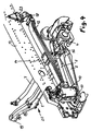
- exemplary embodiments of the steerable vehicle axle for a commercial vehicle especially heavy commercial vehicle shown.
- the illustrated embodiments are vehicle axles in which the steering system and in particular one the steering forces transferring steering device 8 (Fig. 1 to 4) or steering device 9 (Fig. 5) is integrated.
- the vehicle axle with the integrated Steering be designed as a preassembled unit, wherein in this preassembled unit It is also possible for a spring system designed as a leaf spring to be additionally integrated. as the embodiment of FIG. 2 shows.
- the illustrated vehicle axles are designed as rigid axles and have a transverse Achsêt 1 arranged to the vehicle longitudinal direction.
- the axle body 1 is in the vehicle longitudinal direction by means of trailing arms 2, 3, which arranged on both sides of the vehicle longitudinal center plane are, with the vehicle body, in particular longitudinal beams 13 (Fig. 4) connected.
- the axle body 1 shown in the embodiments is a at its two ends bent axle body. However, the axle body 1 can also be used as a straight axle body be educated.
- the trailing arms 2, 3 are at the ends of the straight central region of the Achs emotionss 1 in attachment points 20 connected to the axle 1. In the illustrated Embodiments four attachment points are provided, in which by Screw the trailing arm 2 are attached to the axle 1.
- At her front Ends have the trailing arm 2, 3 bearing eyes 22, in which the trailing arm 2, 3 with the vehicle body, in particular extending on both sides of the vehicle longitudinal median plane Side members 13, of which a longitudinal member is shown in FIG. 4, connected are.
- connection heads 19 for wheel 4 At the two ends of the axle body 1 are connection heads 19 for wheel 4.
- the wheel carrier 4 are in a known manner to steering axles 6 in the connection heads 19th pivoted.
- the steering forces via a steering device 8 (Fig. 1 to 4) or steering device 9 (Fig. 5) transmitted.
- the steering device 8 has a steering gear 10, which on the Trailing arm 2 is attached.
- the attachment point is in the area of the handlebar end, which in the bearing eye 22 with the vehicle body, in particular longitudinal member 13 (Fig. 4) is.
- the steering gear 10 is by means of a holding device 17 which as angled End shield is formed, secured in several screw on the trailing arm 2.
- the steering gear 10 is formed in a known manner and transmits steering movements a steering wheel, not shown, where appropriate in the steering gear a steering gain takes place.
- a steering lever 15 On the output side of the steering gear is a steering lever 15, the pivotal movement via a handlebar 5 on a steering wheel 16 attached to the wheel 4 is transmitted.
- the steering movements of the located on one side of the vehicle wheel carrier 4 are located on a tie rod 7 on the other side of the vehicle transmitted wheel carrier not shown. Since the steering gear 10 with the holding device 17 is attached to the trailing arm 2, arise during compression of the axle only minor Pivoting movements of the steering gear 10 and relative movements between the Components of the axle and the components of the steering system.
- handlebar and wishbone no longer correspond with each other as at conventional axles and steering systems is the case. sen therefore handlebar and wishbone no longer correspond with each other, as at conventional axles and steering systems is the case.
- Fig. 2 is in the preassembled unit also a Leaf suspension with parallel to the trailing arms 2, 3 arranged leaf springs to both Provided sides of the median longitudinal plane of the vehicle.
- Fig. 2 is one of the leaf springs 12 is shown. This extends parallel to the trailing arm 2.
- the leaf spring center is with the help of known clamping means 14 in a certain clamping length fixed to the Achspian 1 connected.
- At the ends of the leaf spring 12 via compensating bearing 18 with a transverse support 23 on the vehicle body, in particular on both sides of the Fixed to the longitudinal center plane of the vehicle arranged longitudinal members 13 (Fig. 4)
- the axle load is sufficient if the spring ends with a lateral end for transmission the transverse support via Abisselzböcke with the side rails 13 are connected.
- the steering device 9 includes an electric or hydraulic actuating cylinder 11.
- the actuating cylinder 11 is preferably attached via a ball joint 24 in the region of the front bar end of the trailing arm 2.
- the adjusting cylinder 11 is the other end via a piston rod 21 with the steering lever 16, which is firmly connected to the wheel carrier 4, connected for transmission of the steering movement.
- the actuating cylinder 11 and the piston rod 21 form a longitudinally movable handlebar Steering 9.
- the outgoing from the steering wheel not shown steering movements or steering forces are in actuation signals for a non-illustrated control valve system converted (steer by wire), which the piston of the actuating cylinder 11 and the rigidly connected piston rod 21 moves accordingly.
- the steering device 9 is fixedly connected to the trailing arm 2 on one side of the vehicle, wherein the steering movement of the wheel carrier 4 on the same side of the vehicle over the Tie rod 7 transmitted to the wheel carrier, not shown, the other side of the vehicle becomes.
- the tie rod 7 can then be omitted.
Landscapes
- Engineering & Computer Science (AREA)
- Mechanical Engineering (AREA)
- Chemical & Material Sciences (AREA)
- Combustion & Propulsion (AREA)
- Transportation (AREA)
- Vehicle Body Suspensions (AREA)
- Steering-Linkage Mechanisms And Four-Wheel Steering (AREA)
Applications Claiming Priority (2)
| Application Number | Priority Date | Filing Date | Title |
|---|---|---|---|
| DE10133937 | 2001-07-12 | ||
| DE10133937A DE10133937A1 (de) | 2001-07-12 | 2001-07-12 | Lenkbare Fahrzeugachse für ein Nutzfahrzeug |
Publications (3)
| Publication Number | Publication Date |
|---|---|
| EP1275574A2 true EP1275574A2 (fr) | 2003-01-15 |
| EP1275574A3 EP1275574A3 (fr) | 2003-07-02 |
| EP1275574B1 EP1275574B1 (fr) | 2004-08-04 |
Family
ID=7691562
Family Applications (1)
| Application Number | Title | Priority Date | Filing Date |
|---|---|---|---|
| EP02013667A Expired - Lifetime EP1275574B1 (fr) | 2001-07-12 | 2002-06-20 | Essieu directeur de véhicule pour un véhicule industriel |
Country Status (3)
| Country | Link |
|---|---|
| EP (1) | EP1275574B1 (fr) |
| DE (2) | DE10133937A1 (fr) |
| TR (1) | TR200401987T4 (fr) |
Cited By (3)
| Publication number | Priority date | Publication date | Assignee | Title |
|---|---|---|---|---|
| EP1800991A1 (fr) | 2005-12-22 | 2007-06-27 | ZF-Lenksysteme GmbH | Essieu directeur |
| EP1839906A1 (fr) * | 2006-03-31 | 2007-10-03 | MAN Nutzfahrzeuge Aktiengesellschaft | Essieu rigide d'un véhicule utilitaire |
| EP2163401A1 (fr) * | 2008-09-15 | 2010-03-17 | MAN Nutzfahrzeuge AG | Corps d'axe pour un axe de véhicule, notamment pour un axe rigid d'un véhicule automobile et/ou utilitaire |
Citations (2)
| Publication number | Priority date | Publication date | Assignee | Title |
|---|---|---|---|---|
| DE19809279A1 (de) | 1998-03-04 | 1999-09-09 | Man Nutzfahrzeuge Ag | Fahrgestell eines schweren Nutzfahrzeuges |
| DE19919845A1 (de) | 1999-04-30 | 2000-11-09 | Trepte Gmbh Metall Und Fahrzeu | Radaufhängung, insbesondere für lenkbare Vorderräder |
Family Cites Families (2)
| Publication number | Priority date | Publication date | Assignee | Title |
|---|---|---|---|---|
| US3970166A (en) * | 1975-01-23 | 1976-07-20 | Sheppard Richard H | Axle mounting of integral power steering gear |
| DE19637997C1 (de) * | 1996-09-18 | 1997-12-11 | Daimler Benz Ag | Zahnstangenlenkung für ein Kraftfahrzeug mit einer Starrachse |
-
2001
- 2001-07-12 DE DE10133937A patent/DE10133937A1/de not_active Withdrawn
-
2002
- 2002-06-20 EP EP02013667A patent/EP1275574B1/fr not_active Expired - Lifetime
- 2002-06-20 DE DE50200735T patent/DE50200735D1/de not_active Expired - Lifetime
- 2002-06-20 TR TR2004/01987T patent/TR200401987T4/xx unknown
Patent Citations (2)
| Publication number | Priority date | Publication date | Assignee | Title |
|---|---|---|---|---|
| DE19809279A1 (de) | 1998-03-04 | 1999-09-09 | Man Nutzfahrzeuge Ag | Fahrgestell eines schweren Nutzfahrzeuges |
| DE19919845A1 (de) | 1999-04-30 | 2000-11-09 | Trepte Gmbh Metall Und Fahrzeu | Radaufhängung, insbesondere für lenkbare Vorderräder |
Cited By (5)
| Publication number | Priority date | Publication date | Assignee | Title |
|---|---|---|---|---|
| EP1800991A1 (fr) | 2005-12-22 | 2007-06-27 | ZF-Lenksysteme GmbH | Essieu directeur |
| DE102005061522A1 (de) * | 2005-12-22 | 2007-07-05 | Zf Lenksysteme Gmbh | Lenkbare Achse |
| EP1839906A1 (fr) * | 2006-03-31 | 2007-10-03 | MAN Nutzfahrzeuge Aktiengesellschaft | Essieu rigide d'un véhicule utilitaire |
| RU2415760C2 (ru) * | 2006-03-31 | 2011-04-10 | Ман Нутцфарцойге Акциенгезелльшафт | Балка жесткого моста транспортного средства |
| EP2163401A1 (fr) * | 2008-09-15 | 2010-03-17 | MAN Nutzfahrzeuge AG | Corps d'axe pour un axe de véhicule, notamment pour un axe rigid d'un véhicule automobile et/ou utilitaire |
Also Published As
| Publication number | Publication date |
|---|---|
| EP1275574B1 (fr) | 2004-08-04 |
| TR200401987T4 (tr) | 2004-09-21 |
| DE10133937A1 (de) | 2003-01-23 |
| EP1275574A3 (fr) | 2003-07-02 |
| DE50200735D1 (de) | 2004-09-09 |
Similar Documents
| Publication | Publication Date | Title |
|---|---|---|
| DE3048864C2 (de) | Achse, insbesondere Hinterachse für Personenkraftwagen, mit unabhängig von einander geführten Rädern | |
| DE102013211458A1 (de) | Unabhängige Radaufhängung für die angetriebenen Räder eines Fahrzeugs | |
| DE102017217190A1 (de) | Mehrlenkerhinterachse und Kraftfahrzeug | |
| EP1080953A1 (fr) | Suspension de roue d'un véhicule automobile à ressort à lame guidant la roue | |
| EP2389298A1 (fr) | Dispositif de stabilisateur sur une suspension de roue de véhicule motorisé | |
| DE102014205632A1 (de) | Einzelradaufhängung sowie Hinterachse mit Einzelradaufhängungen für ein Fahrzeug und entsprechend ausgestattetes Fahrzeug | |
| EP3074296B1 (fr) | Châssis auxiliaire à ressort à lames transversal intégré | |
| DE102011082768A1 (de) | Lenkbare Verbundlenkerachse | |
| DE102010003332A1 (de) | Aktive Hinterradaufhängung | |
| EP1882600B1 (fr) | Essieu à traverse déformable en torsion | |
| DE102014205635A1 (de) | Einzelradaufhängung sowie Hinterachse mit Einzelradaufhängungen für ein Fahrzeug und entsprechend ausgestattetes Fahrzeug | |
| DE102012106965B4 (de) | Aktives Wankstabilisierungssystem | |
| DE102014201621B4 (de) | Verbundlenkerachse für Fahrzeuge | |
| DE202014101432U1 (de) | Einzelradaufhängung sowie Hinterachse mit Einzelradaufhängungen für ein Fahrzeug und entsprechend ausgestattetes Fahrzeug | |
| WO2008098730A1 (fr) | Essieu de véhicule à deux voies comprenant une bielle composite souple du point de vue de la torsion | |
| WO2019037946A1 (fr) | Essieu de véhicule doté d'une unité d'entraînement montée de manière centrale | |
| DE102009032644A1 (de) | Halbstarrachse, insbesondere Koppellenker - oder Verbundlenkerachse eines mehrspurigen Kraftfahrzeuges | |
| WO2020187464A1 (fr) | Suspension de roue pour essieu de véhicule | |
| EP1275574B1 (fr) | Essieu directeur de véhicule pour un véhicule industriel | |
| DE102004058748B4 (de) | Mehrlenker-Hinterradaufhängung | |
| EP3319821B1 (fr) | Essieu à bras transversaux superposés | |
| WO2017137185A1 (fr) | Axe de bras oscillant composite orientable | |
| EP1277603B1 (fr) | Suspension de roue indépendante multibras, en particulier suspension d'une roue avant directrice pour véhicule automobile | |
| DE102008004089A1 (de) | Schraubenfeder für ein Fahrwerk | |
| DE202013100881U1 (de) | Verbundlenkerachse für Fahrzeuge |
Legal Events
| Date | Code | Title | Description |
|---|---|---|---|
| PUAI | Public reference made under article 153(3) epc to a published international application that has entered the european phase |
Free format text: ORIGINAL CODE: 0009012 |
|
| AK | Designated contracting states |
Kind code of ref document: A2 Designated state(s): AT BE CH CY DE DK ES FI FR GB GR IE IT LI LU MC NL PT SE TR |
|
| AX | Request for extension of the european patent |
Free format text: AL;LT;LV;MK;RO;SI |
|
| PUAL | Search report despatched |
Free format text: ORIGINAL CODE: 0009013 |
|
| AK | Designated contracting states |
Designated state(s): AT BE CH CY DE DK ES FI FR GB GR IE IT LI LU MC NL PT SE TR |
|
| AX | Request for extension of the european patent |
Extension state: AL LT LV MK RO SI |
|
| 17P | Request for examination filed |
Effective date: 20030717 |
|
| GRAP | Despatch of communication of intention to grant a patent |
Free format text: ORIGINAL CODE: EPIDOSNIGR1 |
|
| AKX | Designation fees paid |
Designated state(s): DE FR IT NL SE TR |
|
| GRAS | Grant fee paid |
Free format text: ORIGINAL CODE: EPIDOSNIGR3 |
|
| GRAA | (expected) grant |
Free format text: ORIGINAL CODE: 0009210 |
|
| AK | Designated contracting states |
Kind code of ref document: B1 Designated state(s): DE FR IT NL SE TR |
|
| REG | Reference to a national code |
Ref country code: IE Ref legal event code: FG4D Free format text: GERMAN |
|
| REF | Corresponds to: |
Ref document number: 50200735 Country of ref document: DE Date of ref document: 20040909 Kind code of ref document: P |
|
| REG | Reference to a national code |
Ref country code: SE Ref legal event code: TRGR |
|
| REG | Reference to a national code |
Ref country code: IE Ref legal event code: FD4D |
|
| PLBE | No opposition filed within time limit |
Free format text: ORIGINAL CODE: 0009261 |
|
| STAA | Information on the status of an ep patent application or granted ep patent |
Free format text: STATUS: NO OPPOSITION FILED WITHIN TIME LIMIT |
|
| ET | Fr: translation filed | ||
| 26N | No opposition filed |
Effective date: 20050506 |
|
| REG | Reference to a national code |
Ref country code: NL Ref legal event code: TD Effective date: 20110420 |
|
| REG | Reference to a national code |
Ref country code: FR Ref legal event code: CD |
|
| REG | Reference to a national code |
Ref country code: DE Ref legal event code: R081 Ref document number: 50200735 Country of ref document: DE Owner name: MAN TRUCK BUS AG, DE Free format text: FORMER OWNER: MAN NUTZFAHRZEUGE AKTIENGESELLSCHAFT, 80995 MUENCHEN, DE Effective date: 20110518 Ref country code: DE Ref legal event code: R081 Ref document number: 50200735 Country of ref document: DE Owner name: MAN TRUCK & BUS AG, DE Free format text: FORMER OWNER: MAN NUTZFAHRZEUGE AKTIENGESELLSCHAFT, 80995 MUENCHEN, DE Effective date: 20110518 |
|
| REG | Reference to a national code |
Ref country code: FR Ref legal event code: PLFP Year of fee payment: 15 |
|
| REG | Reference to a national code |
Ref country code: FR Ref legal event code: PLFP Year of fee payment: 16 |
|
| REG | Reference to a national code |
Ref country code: FR Ref legal event code: PLFP Year of fee payment: 17 |
|
| REG | Reference to a national code |
Ref country code: DE Ref legal event code: R081 Ref document number: 50200735 Country of ref document: DE Owner name: MAN TRUCK & BUS SE, DE Free format text: FORMER OWNER: MAN TRUCK & BUS AG, 80995 MUENCHEN, DE |
|
| PGFP | Annual fee paid to national office [announced via postgrant information from national office to epo] |
Ref country code: FR Payment date: 20210625 Year of fee payment: 20 Ref country code: IT Payment date: 20210622 Year of fee payment: 20 Ref country code: NL Payment date: 20210628 Year of fee payment: 20 |
|
| PGFP | Annual fee paid to national office [announced via postgrant information from national office to epo] |
Ref country code: TR Payment date: 20210609 Year of fee payment: 20 Ref country code: SE Payment date: 20210622 Year of fee payment: 20 |
|
| PGFP | Annual fee paid to national office [announced via postgrant information from national office to epo] |
Ref country code: DE Payment date: 20210827 Year of fee payment: 20 |
|
| REG | Reference to a national code |
Ref country code: DE Ref legal event code: R071 Ref document number: 50200735 Country of ref document: DE |
|
| REG | Reference to a national code |
Ref country code: NL Ref legal event code: MK Effective date: 20220619 |
|
| REG | Reference to a national code |
Ref country code: SE Ref legal event code: EUG |