EP1275732A1 - Capteur electrochimique avec un système de détection de sous-remplissage - Google Patents
Capteur electrochimique avec un système de détection de sous-remplissage Download PDFInfo
- Publication number
- EP1275732A1 EP1275732A1 EP02012365A EP02012365A EP1275732A1 EP 1275732 A1 EP1275732 A1 EP 1275732A1 EP 02012365 A EP02012365 A EP 02012365A EP 02012365 A EP02012365 A EP 02012365A EP 1275732 A1 EP1275732 A1 EP 1275732A1
- Authority
- EP
- European Patent Office
- Prior art keywords
- sample
- conductor
- test sensor
- capillary channel
- test
- Prior art date
- Legal status (The legal status is an assumption and is not a legal conclusion. Google has not performed a legal analysis and makes no representation as to the accuracy of the status listed.)
- Granted
Links
- 238000001514 detection method Methods 0.000 title description 3
- 238000000840 electrochemical analysis Methods 0.000 title 1
- 238000012360 testing method Methods 0.000 claims abstract description 79
- 239000004020 conductor Substances 0.000 claims abstract description 42
- 239000007788 liquid Substances 0.000 claims abstract description 20
- 239000003153 chemical reaction reagent Substances 0.000 claims abstract description 10
- 239000012491 analyte Substances 0.000 claims abstract description 9
- 238000004891 communication Methods 0.000 claims abstract description 3
- 239000012530 fluid Substances 0.000 claims abstract description 3
- 239000011248 coating agent Substances 0.000 claims description 21
- 238000000576 coating method Methods 0.000 claims description 21
- 125000006850 spacer group Chemical group 0.000 claims description 11
- 238000000034 method Methods 0.000 claims description 7
- 230000008859 change Effects 0.000 claims description 4
- 230000011664 signaling Effects 0.000 claims 2
- 229910000838 Al alloy Inorganic materials 0.000 claims 1
- 229910001339 C alloy Inorganic materials 0.000 claims 1
- 239000008280 blood Substances 0.000 description 64
- 210000004369 blood Anatomy 0.000 description 64
- WQZGKKKJIJFFOK-GASJEMHNSA-N Glucose Natural products OC[C@H]1OC(O)[C@H](O)[C@@H](O)[C@@H]1O WQZGKKKJIJFFOK-GASJEMHNSA-N 0.000 description 22
- 239000008103 glucose Substances 0.000 description 22
- 238000006243 chemical reaction Methods 0.000 description 4
- 230000009471 action Effects 0.000 description 3
- 238000010276 construction Methods 0.000 description 3
- 238000012544 monitoring process Methods 0.000 description 3
- 208000013016 Hypoglycemia Diseases 0.000 description 2
- 230000008901 benefit Effects 0.000 description 2
- 238000003306 harvesting Methods 0.000 description 2
- 201000001421 hyperglycemia Diseases 0.000 description 2
- 230000002218 hypoglycaemic effect Effects 0.000 description 2
- 230000001788 irregular Effects 0.000 description 2
- 238000012986 modification Methods 0.000 description 2
- 230000004048 modification Effects 0.000 description 2
- 238000004544 sputter deposition Methods 0.000 description 2
- OKTJSMMVPCPJKN-UHFFFAOYSA-N Carbon Chemical compound [C] OKTJSMMVPCPJKN-UHFFFAOYSA-N 0.000 description 1
- XAGFODPZIPBFFR-UHFFFAOYSA-N aluminium Chemical compound [Al] XAGFODPZIPBFFR-UHFFFAOYSA-N 0.000 description 1
- 229910052782 aluminium Inorganic materials 0.000 description 1
- 230000001588 bifunctional effect Effects 0.000 description 1
- 230000015572 biosynthetic process Effects 0.000 description 1
- 229910052799 carbon Inorganic materials 0.000 description 1
- 238000005520 cutting process Methods 0.000 description 1
- 206010012601 diabetes mellitus Diseases 0.000 description 1
- 230000001771 impaired effect Effects 0.000 description 1
- 238000004519 manufacturing process Methods 0.000 description 1
- 230000007246 mechanism Effects 0.000 description 1
- 230000003647 oxidation Effects 0.000 description 1
- 238000007254 oxidation reaction Methods 0.000 description 1
- 238000007747 plating Methods 0.000 description 1
- 230000008569 process Effects 0.000 description 1
- 238000001771 vacuum deposition Methods 0.000 description 1
- 230000000007 visual effect Effects 0.000 description 1
Images

Classifications
-
- C—CHEMISTRY; METALLURGY
- C12—BIOCHEMISTRY; BEER; SPIRITS; WINE; VINEGAR; MICROBIOLOGY; ENZYMOLOGY; MUTATION OR GENETIC ENGINEERING
- C12Q—MEASURING OR TESTING PROCESSES INVOLVING ENZYMES, NUCLEIC ACIDS OR MICROORGANISMS; COMPOSITIONS OR TEST PAPERS THEREFOR; PROCESSES OF PREPARING SUCH COMPOSITIONS; CONDITION-RESPONSIVE CONTROL IN MICROBIOLOGICAL OR ENZYMOLOGICAL PROCESSES
- C12Q1/00—Measuring or testing processes involving enzymes, nucleic acids or microorganisms; Compositions therefor; Processes of preparing such compositions
- C12Q1/001—Enzyme electrodes
- C12Q1/005—Enzyme electrodes involving specific analytes or enzymes
- C12Q1/006—Enzyme electrodes involving specific analytes or enzymes for glucose
-
- G—PHYSICS
- G01—MEASURING; TESTING
- G01N—INVESTIGATING OR ANALYSING MATERIALS BY DETERMINING THEIR CHEMICAL OR PHYSICAL PROPERTIES
- G01N27/00—Investigating or analysing materials by the use of electric, electrochemical, or magnetic means
- G01N27/26—Investigating or analysing materials by the use of electric, electrochemical, or magnetic means by investigating electrochemical variables; by using electrolysis or electrophoresis
- G01N27/28—Electrolytic cell components
- G01N27/30—Electrodes, e.g. test electrodes; Half-cells
- G01N27/327—Biochemical electrodes, e.g. electrical or mechanical details for in vitro measurements
- G01N27/3271—Amperometric enzyme electrodes for analytes in body fluids, e.g. glucose in blood
- G01N27/3272—Test elements therefor, i.e. disposable laminated substrates with electrodes, reagent and channels
-
- G—PHYSICS
- G01—MEASURING; TESTING
- G01N—INVESTIGATING OR ANALYSING MATERIALS BY DETERMINING THEIR CHEMICAL OR PHYSICAL PROPERTIES
- G01N27/00—Investigating or analysing materials by the use of electric, electrochemical, or magnetic means
- G01N27/26—Investigating or analysing materials by the use of electric, electrochemical, or magnetic means by investigating electrochemical variables; by using electrolysis or electrophoresis
- G01N27/28—Electrolytic cell components
- G01N27/30—Electrodes, e.g. test electrodes; Half-cells
- G01N27/308—Electrodes, e.g. test electrodes; Half-cells at least partially made of carbon
Definitions
- the present invention relates generally to electrochemical biosensing for quantifying a specific component (analyte) in a liquid sample, and more particularly, to an underfill detection system for use with an electrochemical biosensor.
- a sample of blood It is often necessary to quickly obtain a sample of blood and perform an analysis of the blood sample.
- One example of a need for obtaining a sample of blood is in connection with a blood glucose monitoring system, which a user must frequently use to monitor the user's blood glucose level.
- Those who have irregular blood glucose concentration levels are medically required to regularly self-monitor their blood glucose concentration level.
- An irregular blood glucose level can be brought on by a variety of reasons including illness such as diabetes.
- the purpose of monitoring the blood glucose concentration level is to determine the blood glucose concentration level and then to take corrective action, based upon whether the level is too high or too low, to bring the level back within a normal range.
- the failure to take corrective action can have serious implications.
- blood glucose levels drop too low - known as hypoglycemia -
- a person can become nervous, shaky, and confused. That person's judgment may become impaired and that person may eventually pass out.
- a person can also become very ill if their blood glucose level becomes too high - a condition known as hyperglycemia. Both conditions, hypoglycemia and hyperglycemia, are potentially life-threatening emergencies.
- the glucose testing device includes a test sensor to harvest the blood for analysis.
- a test sensor is described in U.S. Patent No. 5,759,364, which is entitled "Electrochemical Biosensor.”
- a drop of blood is obtained from the fingertip using a lancing device.
- the blood drop is produced on the fingertip and the blood is harvested using the test sensor.
- the test sensor which is inserted into a testing unit, is brought into contact with the blood drop.
- the test sensor draws the blood to the inside of the test unit which then determines the concentration of glucose in the blood. Once the results of the test are displayed on a display of the test unit, the test sensor is discarded. Each new test requires a new test sensor.
- test units come with instructions graphically illustrating the size of the blood drop required for accurate testing.
- this visual comparison is subjective and often produces inconsistent results.
- users often overcompensate by squeezing or otherwise manipulating their finger to produce a larger than necessary drop of blood.
- this adds time to the overall testing process and also results in an increased amount of wasted blood. It is preferable to require/obtain as little of the user's blood as possible for accurate results. Put another way, it is desirable to only obtain the required amount of blood.
- a test sensor having a pair of electrodes and a reagent for electrochemically measuring the concentration of the analyte in a liquid sample.
- the test sensor comprises a capillary channel for collecting the liquid sample and a conductor disposed outside the capillary channel. The conductor is in fluid communication with the capillary channel. The liquid test sample is collected and moved through the capillary channel. The liquid test sample contacts the conductor when the capillary channel is substantially full to signal a full condition.
- test sensors are commonly used to measure the amount of glucose in a person's blood.
- One type of sensor for use in the determination of a person's blood glucose level is an electrochemical sensor. Such a sensor is described in commonly owned U.S. Patent No. 5,759,364, which is incorporated herein by reference in its entirety.
- Other types of sensing include colorimetric sensing, which is described in commonly owned U.S. Patent No. 5,723,284, which is incorporated herein by reference in its entirety.
- the test sensor 10 includes a base plate 12 and a lid 14.
- the base plate 12 includes a working electrode 16 and a counter-reference electrode 18 printed on the surface of the base plate 12.
- the lid 14 includes a raised portion 20, the underside of which forms three side of a capillary channel 22.
- the base plate 12 forms the fourth side of the capillary channel 22 when the lid 14 is mated to the base plate 12.
- the base plate 12 also includes a reaction area or test area 24 that is generally illustrated with a dashed line. The circular area indicated by the dotted line is shown greater detail in FIG. 2.
- the base plate 12 includes a reagent 26 incorporated into the test area 24.
- the reagent 26 is designed to react with the glucose in blood 28 that has moved though the capillary channel 22 to the test area 24. This reaction produces a change in current across the electrodes 16,18 that is indicative of the concentration of glucose in the sample of blood. Put another way, the reaction of glucose and the reagent creates an oxidation current at the electrodes 16,18 which is directly proportional to the user's blood glucose concentration. This current can be measured by an appropriate meter (not shown) electrically coupled to a pair of terminals 30,32 corresponding to the electrodes 16,18.
- the user lances the user's fingertip to produce a sample of blood.
- the test sensor 10 is typically inserted into a testing device, with the sample collection end 25 exposed.
- the sample collection end 25 is brought into contact with the blood sample.
- Blood moves, via capillary action, from the collection end 25 of the sensor 10 into the test area 24 wherein the blood mixes and reacts with the reagent.
- displaced air vents from the capillary channel 22 via a vent hole 34.
- the ensuing reaction produces a change in current that is measurable across the electrodes 16,18.
- the change in current is measured by a meter that is coupled to the terminals 30,32.
- the test sensor is equipped with a third electrode - a signal electrode.
- the signal electrode is not printed on the base plate 12 nor placed on the under surface of the lid 14 so that the signal electrode faces the capillary channel 22. Rather, a conductor 36 is formed on the outer surface of the lid 14 by coating the outer surface with a conductive material. The conductor 36 forms the terminal for the signal electrode and the working electrode 16 serves as the second electrode for the signal electrode circuit.
- the vent hole is placed at a distance so that the capillary channel 22, when filled, provides the necessary volume for a sufficient blood sample to be harvested.
- the sample has to make contact with the conductor 36 to signal a full condition.
- a sufficient volume of blood moves though the capillary channel 22 into the vent hole 34, the blood contacts the conductor 36 to form a conductive path between the conductor 36 and the working electrode 16.
- the formation of the conductive path indicates that a sufficient sample volume is present for accurate testing.
- this path can be part of a circuit coupled to an LED which is illuminated when the conductive path is formed.
- the entire lid 14 is coated with the conductive coating.
- a line 38 is scribed in the conductive coating to electrically isolate the conductor 36 from a sample collection end 25 of the lid 14.
- the lid sample collection end 25 (as well as the base plate collection end 25) contact the blood sample. If the lid sample collection end 25 was not isolated from the conductor 36, a conductive path would be formed from one of the conductors 16,18 though the capillary channel 22 to the lid sample collection end 25 which has been coated with a conductive coating. Such a conductive path would incorrectly signal that a sufficient sample has been collected.
- the conductor 36 is formed by coating the lid 14 with a film of Du Pont 7102T carbon to a dry thickness of 7 ⁇ m.
- the vent hole 34 has a diameter of approximately 0.050 inch (about 0.127 mm).
- the conductor is formed by coating the lid 14 with an aluminum film.
- Methods of covering the lid 14 with the conductive material include coating, sputter coating, vacuum deposition, and plating.
- An alternative to coating the entire lid 14 with a conductive layer followed by scoring a line 38 to electrically isolate the conductor 36 from the sample collection end 25, is to place the conductive material in only the desired area using techniques such as zone coating, zone sputtering, and printing.
- the capillary channel 22 is designed so that only the requisite amount of blood for accurate testing is collected by the test sensor 10. Ideally, the signal electrode would be placed at the exact level of the working electrode 16. However, this is not desirable because this arrangement would short out the working electrode 16. Therefore, the signal electrode must be spaced from the working electrode 16.
- the inventor has found that, due in part to printing tolerances, spacing the signal electrode away from the working electrode would require the capillary channel 22 to be approximately 0.025 inch (about 0.064 mm) longer. This in turn increases the capillary area, which translates into an increased blood sample volume. This is counterproductive because, as described in the background section, it is desirable to minimize the amount of blood required for an accurate analysis.
- the underside of the raised portion 20 of the lid 14 carries a bifunctional coating that facilitates the movement of the blood though the capillary channel 22. Placing the signal electrode on the underside of the raised portion 20 of the lid 14 would impede the movement of blood to the test area and increase the overall time to conduct the test.
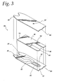
- FIG. 3 an alternative embodiment of a test sensor 50 is shown.
- the sensor 10 shown in FIG 1 has a "two-piece construction” (i.e. , the base plate 12 and the lid 14)
- the sensor 50 illustrated in FIG. 3 has a "three-piece construction” - a base plate 12, a spacer 54, and a lid 56.
- a "three-piece construction” sensor is described in U.S. Patent No. 5,120,420, which is hereby incorporated by reference in its entirety.
- the base plate 12 is similar to the base plate 12 illustrated in FIG. 1 in that it includes electrodes 16,18 electrically coupled to terminals 30,32, respectively. Further, a reagent is incorporated into the base plate 12 to react with a blood sample at the test area 24 indicated generally by dashed lines.
- the lid 56 includes a vent hole 52 that allows air to escape from the test sensor 50 when collecting blood.
- the test sensor 50 differs from the test sensor 10 (FIG. 1) in that the lid 56 for the test sensor 50 is not deformed so as to form a capillary channel. Rather, the spacer 54 for the test sensor 50 includes a cutout which forms a capillary channel 58. The upper surface of the spacer 54 is coated with a conductive material to form a conductor 60. According to one embodiment of the present invention, the spacer is formed by first coating the spacer 54 with the conductive coating and then cutting the capillary channel 58 in the spacer 54 and conductor 60. The edges of the conductive coating are exposed to the sample in the capillary channel 58.
- a line 62 is scribed through the conductor 60 to electrically isolate a sample collection end 64 of the spacer 54 from the conductor 60. Once the sample fills the capillary channel 58 past the line 62, the blood sample contacts the exposed portion ( i.e. , the sides) of the conductor 60 to signal a full condition.
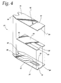
- the lid 56 has a conductor 70 disposed thereon rather than the spacer 54.
- the vent hole 52 is positioned such that when blood fills the capillary channel and moves though the vent hole 52 to contact the conductor 70 conductive coating on the lid 56 a full condition is signaled.
- the conductor 70 is electrically isolated from the collection end 64 by a line 72 scribed through the conductive coating. This embodiment is similar to that shown in described in connection with FIGS. 1 and 2.
Landscapes
- Chemical & Material Sciences (AREA)
- Health & Medical Sciences (AREA)
- Life Sciences & Earth Sciences (AREA)
- Organic Chemistry (AREA)
- Biochemistry (AREA)
- Zoology (AREA)
- Biophysics (AREA)
- Proteomics, Peptides & Aminoacids (AREA)
- Engineering & Computer Science (AREA)
- General Health & Medical Sciences (AREA)
- Immunology (AREA)
- Analytical Chemistry (AREA)
- Molecular Biology (AREA)
- Physics & Mathematics (AREA)
- Wood Science & Technology (AREA)
- Bioinformatics & Cheminformatics (AREA)
- General Physics & Mathematics (AREA)
- Microbiology (AREA)
- General Engineering & Computer Science (AREA)
- Biotechnology (AREA)
- Genetics & Genomics (AREA)
- Hematology (AREA)
- Chemical Kinetics & Catalysis (AREA)
- Electrochemistry (AREA)
- Emergency Medicine (AREA)
- Pathology (AREA)
- Investigating Or Analysing Biological Materials (AREA)
- Measurement Of The Respiration, Hearing Ability, Form, And Blood Characteristics Of Living Organisms (AREA)
- Tests Of Electric Status Of Batteries (AREA)
- Secondary Cells (AREA)
- Investigating Or Analyzing Materials By The Use Of Electric Means (AREA)
- Primary Cells (AREA)
Applications Claiming Priority (2)
| Application Number | Priority Date | Filing Date | Title |
|---|---|---|---|
| US29691001P | 2001-06-11 | 2001-06-11 | |
| US296910P | 2001-06-11 |
Publications (2)
| Publication Number | Publication Date |
|---|---|
| EP1275732A1 true EP1275732A1 (fr) | 2003-01-15 |
| EP1275732B1 EP1275732B1 (fr) | 2008-01-30 |
Family
ID=23144071
Family Applications (1)
| Application Number | Title | Priority Date | Filing Date |
|---|---|---|---|
| EP02012365A Expired - Lifetime EP1275732B1 (fr) | 2001-06-11 | 2002-06-06 | Capteur electrochimique avec un système de détection de sous-remplissage |
Country Status (10)
| Country | Link |
|---|---|
| US (1) | US6960287B2 (fr) |
| EP (1) | EP1275732B1 (fr) |
| JP (1) | JP3850757B2 (fr) |
| AT (1) | ATE385258T1 (fr) |
| AU (1) | AU784316B2 (fr) |
| CA (1) | CA2387599A1 (fr) |
| DE (1) | DE60224863T2 (fr) |
| DK (1) | DK1275732T3 (fr) |
| ES (1) | ES2299540T3 (fr) |
| PT (1) | PT1275732E (fr) |
Cited By (8)
| Publication number | Priority date | Publication date | Assignee | Title |
|---|---|---|---|---|
| WO2004113913A1 (fr) * | 2003-06-20 | 2004-12-29 | Roche Diagnostics Gmbh | Systeme et procede de mesure de substances a analyser utilisant un decalage d'heure posologique maximal |
| WO2005008231A1 (fr) * | 2003-06-20 | 2005-01-27 | Roche Diagnostics Gmbh | Systeme et procede de mesure d'analyte dans des liquides biologiques a l'aide d'electrodes de suffisance de dose |
| US7727467B2 (en) | 2003-06-20 | 2010-06-01 | Roche Diagnostics Operations, Inc. | Reagent stripe for test strip |
| WO2010088770A1 (fr) * | 2009-02-05 | 2010-08-12 | National Research Council Of Canada | Capteur pour mesurer la concentration d'un solvant ou d'un soluté dans un système mixte en solution |
| US8071030B2 (en) | 2003-06-20 | 2011-12-06 | Roche Diagnostics Operations, Inc. | Test strip with flared sample receiving chamber |
| US8287703B2 (en) | 1999-10-04 | 2012-10-16 | Roche Diagnostics Operations, Inc. | Biosensor and method of making |
| US8298828B2 (en) | 2003-06-20 | 2012-10-30 | Roche Diagnostics Operations, Inc. | System and method for determining the concentration of an analyte in a sample fluid |
| US8343332B2 (en) | 2006-07-11 | 2013-01-01 | Bayer Healthcare Llc | Electrochemical test sensor |
Families Citing this family (89)
| Publication number | Priority date | Publication date | Assignee | Title |
|---|---|---|---|---|
| US6036924A (en) | 1997-12-04 | 2000-03-14 | Hewlett-Packard Company | Cassette of lancet cartridges for sampling blood |
| US8071384B2 (en) | 1997-12-22 | 2011-12-06 | Roche Diagnostics Operations, Inc. | Control and calibration solutions and methods for their use |
| US6391005B1 (en) | 1998-03-30 | 2002-05-21 | Agilent Technologies, Inc. | Apparatus and method for penetration with shaft having a sensor for sensing penetration depth |
| DE10057832C1 (de) | 2000-11-21 | 2002-02-21 | Hartmann Paul Ag | Blutanalysegerät |
| US8641644B2 (en) | 2000-11-21 | 2014-02-04 | Sanofi-Aventis Deutschland Gmbh | Blood testing apparatus having a rotatable cartridge with multiple lancing elements and testing means |
| US7344507B2 (en) | 2002-04-19 | 2008-03-18 | Pelikan Technologies, Inc. | Method and apparatus for lancet actuation |
| US9427532B2 (en) | 2001-06-12 | 2016-08-30 | Sanofi-Aventis Deutschland Gmbh | Tissue penetration device |
| CA2448902C (fr) | 2001-06-12 | 2010-09-07 | Pelikan Technologies, Inc. | Autopiqueur a optimisation automatique presentant des moyens d'adaptation aux variations temporelles des proprietes cutanees |
| AU2002348683A1 (en) | 2001-06-12 | 2002-12-23 | Pelikan Technologies, Inc. | Method and apparatus for lancet launching device integrated onto a blood-sampling cartridge |
| WO2002100460A2 (fr) | 2001-06-12 | 2002-12-19 | Pelikan Technologies, Inc. | Actionneur electrique de lancette |
| US7041068B2 (en) | 2001-06-12 | 2006-05-09 | Pelikan Technologies, Inc. | Sampling module device and method |
| US9795747B2 (en) | 2010-06-02 | 2017-10-24 | Sanofi-Aventis Deutschland Gmbh | Methods and apparatus for lancet actuation |
| WO2002100461A2 (fr) | 2001-06-12 | 2002-12-19 | Pelikan Technologies, Inc. | Dispositif et procede permettant d'ameliorer le rendement du prelevement de sang capillaire au bout du doigt |
| US7981056B2 (en) | 2002-04-19 | 2011-07-19 | Pelikan Technologies, Inc. | Methods and apparatus for lancet actuation |
| US7682318B2 (en) | 2001-06-12 | 2010-03-23 | Pelikan Technologies, Inc. | Blood sampling apparatus and method |
| US7537571B2 (en) | 2001-06-12 | 2009-05-26 | Pelikan Technologies, Inc. | Integrated blood sampling analysis system with multi-use sampling module |
| US9226699B2 (en) | 2002-04-19 | 2016-01-05 | Sanofi-Aventis Deutschland Gmbh | Body fluid sampling module with a continuous compression tissue interface surface |
| US8337419B2 (en) | 2002-04-19 | 2012-12-25 | Sanofi-Aventis Deutschland Gmbh | Tissue penetration device |
| US7344894B2 (en) | 2001-10-16 | 2008-03-18 | Agilent Technologies, Inc. | Thermal regulation of fluidic samples within a diagnostic cartridge |
| US7331931B2 (en) | 2002-04-19 | 2008-02-19 | Pelikan Technologies, Inc. | Method and apparatus for penetrating tissue |
| US7892183B2 (en) | 2002-04-19 | 2011-02-22 | Pelikan Technologies, Inc. | Method and apparatus for body fluid sampling and analyte sensing |
| US7563232B2 (en) | 2002-04-19 | 2009-07-21 | Pelikan Technologies, Inc. | Method and apparatus for penetrating tissue |
| US8267870B2 (en) | 2002-04-19 | 2012-09-18 | Sanofi-Aventis Deutschland Gmbh | Method and apparatus for body fluid sampling with hybrid actuation |
| US7374544B2 (en) | 2002-04-19 | 2008-05-20 | Pelikan Technologies, Inc. | Method and apparatus for penetrating tissue |
| US8784335B2 (en) | 2002-04-19 | 2014-07-22 | Sanofi-Aventis Deutschland Gmbh | Body fluid sampling device with a capacitive sensor |
| US7141058B2 (en) | 2002-04-19 | 2006-11-28 | Pelikan Technologies, Inc. | Method and apparatus for a body fluid sampling device using illumination |
| US7297122B2 (en) | 2002-04-19 | 2007-11-20 | Pelikan Technologies, Inc. | Method and apparatus for penetrating tissue |
| US7547287B2 (en) | 2002-04-19 | 2009-06-16 | Pelikan Technologies, Inc. | Method and apparatus for penetrating tissue |
| US7491178B2 (en) | 2002-04-19 | 2009-02-17 | Pelikan Technologies, Inc. | Method and apparatus for penetrating tissue |
| US9248267B2 (en) | 2002-04-19 | 2016-02-02 | Sanofi-Aventis Deustchland Gmbh | Tissue penetration device |
| US7229458B2 (en) | 2002-04-19 | 2007-06-12 | Pelikan Technologies, Inc. | Method and apparatus for penetrating tissue |
| US8702624B2 (en) | 2006-09-29 | 2014-04-22 | Sanofi-Aventis Deutschland Gmbh | Analyte measurement device with a single shot actuator |
| US7524293B2 (en) | 2002-04-19 | 2009-04-28 | Pelikan Technologies, Inc. | Method and apparatus for penetrating tissue |
| US7481776B2 (en) | 2002-04-19 | 2009-01-27 | Pelikan Technologies, Inc. | Method and apparatus for penetrating tissue |
| US8221334B2 (en) | 2002-04-19 | 2012-07-17 | Sanofi-Aventis Deutschland Gmbh | Method and apparatus for penetrating tissue |
| US9795334B2 (en) | 2002-04-19 | 2017-10-24 | Sanofi-Aventis Deutschland Gmbh | Method and apparatus for penetrating tissue |
| US7582099B2 (en) | 2002-04-19 | 2009-09-01 | Pelikan Technologies, Inc | Method and apparatus for penetrating tissue |
| US7410468B2 (en) | 2002-04-19 | 2008-08-12 | Pelikan Technologies, Inc. | Method and apparatus for penetrating tissue |
| US7371247B2 (en) | 2002-04-19 | 2008-05-13 | Pelikan Technologies, Inc | Method and apparatus for penetrating tissue |
| US7291117B2 (en) | 2002-04-19 | 2007-11-06 | Pelikan Technologies, Inc. | Method and apparatus for penetrating tissue |
| US8579831B2 (en) | 2002-04-19 | 2013-11-12 | Sanofi-Aventis Deutschland Gmbh | Method and apparatus for penetrating tissue |
| US7976476B2 (en) | 2002-04-19 | 2011-07-12 | Pelikan Technologies, Inc. | Device and method for variable speed lancet |
| US7226461B2 (en) | 2002-04-19 | 2007-06-05 | Pelikan Technologies, Inc. | Method and apparatus for a multi-use body fluid sampling device with sterility barrier release |
| US7232451B2 (en) | 2002-04-19 | 2007-06-19 | Pelikan Technologies, Inc. | Method and apparatus for penetrating tissue |
| US9314194B2 (en) | 2002-04-19 | 2016-04-19 | Sanofi-Aventis Deutschland Gmbh | Tissue penetration device |
| US7901362B2 (en) | 2002-04-19 | 2011-03-08 | Pelikan Technologies, Inc. | Method and apparatus for penetrating tissue |
| US7674232B2 (en) | 2002-04-19 | 2010-03-09 | Pelikan Technologies, Inc. | Method and apparatus for penetrating tissue |
| US7648468B2 (en) | 2002-04-19 | 2010-01-19 | Pelikon Technologies, Inc. | Method and apparatus for penetrating tissue |
| US7909778B2 (en) | 2002-04-19 | 2011-03-22 | Pelikan Technologies, Inc. | Method and apparatus for penetrating tissue |
| US7717863B2 (en) | 2002-04-19 | 2010-05-18 | Pelikan Technologies, Inc. | Method and apparatus for penetrating tissue |
| US6964871B2 (en) | 2002-04-25 | 2005-11-15 | Home Diagnostics, Inc. | Systems and methods for blood glucose sensing |
| US20080112852A1 (en) * | 2002-04-25 | 2008-05-15 | Neel Gary T | Test Strips and System for Measuring Analyte Levels in a Fluid Sample |
| US6946299B2 (en) | 2002-04-25 | 2005-09-20 | Home Diagnostics, Inc. | Systems and methods for blood glucose sensing |
| US6743635B2 (en) | 2002-04-25 | 2004-06-01 | Home Diagnostics, Inc. | System and methods for blood glucose sensing |
| WO2004051249A1 (fr) * | 2002-12-02 | 2004-06-17 | Arkray, Inc. | Instrument d'analyse |
| US8574895B2 (en) | 2002-12-30 | 2013-11-05 | Sanofi-Aventis Deutschland Gmbh | Method and apparatus using optical techniques to measure analyte levels |
| ES2490740T3 (es) | 2003-06-06 | 2014-09-04 | Sanofi-Aventis Deutschland Gmbh | Aparato para toma de muestras de fluido sanguíneo y detección de analitos |
| WO2006001797A1 (fr) | 2004-06-14 | 2006-01-05 | Pelikan Technologies, Inc. | Element penetrant peu douloureux |
| US7604592B2 (en) | 2003-06-13 | 2009-10-20 | Pelikan Technologies, Inc. | Method and apparatus for a point of care device |
| US8206565B2 (en) | 2003-06-20 | 2012-06-26 | Roche Diagnostics Operation, Inc. | System and method for coding information on a biosensor test strip |
| US8679853B2 (en) | 2003-06-20 | 2014-03-25 | Roche Diagnostics Operations, Inc. | Biosensor with laser-sealed capillary space and method of making |
| US8058077B2 (en) | 2003-06-20 | 2011-11-15 | Roche Diagnostics Operations, Inc. | Method for coding information on a biosensor test strip |
| US7645421B2 (en) | 2003-06-20 | 2010-01-12 | Roche Diagnostics Operations, Inc. | System and method for coding information on a biosensor test strip |
| US7604721B2 (en) | 2003-06-20 | 2009-10-20 | Roche Diagnostics Operations, Inc. | System and method for coding information on a biosensor test strip |
| US7718439B2 (en) | 2003-06-20 | 2010-05-18 | Roche Diagnostics Operations, Inc. | System and method for coding information on a biosensor test strip |
| US7645373B2 (en) | 2003-06-20 | 2010-01-12 | Roche Diagnostic Operations, Inc. | System and method for coding information on a biosensor test strip |
| EP1671096A4 (fr) | 2003-09-29 | 2009-09-16 | Pelikan Technologies Inc | Procede et appareil permettant d'obtenir un dispositif de capture d'echantillons ameliore |
| EP1680014A4 (fr) | 2003-10-14 | 2009-01-21 | Pelikan Technologies Inc | Procede et appareil fournissant une interface-utilisateur variable |
| KR100579489B1 (ko) * | 2003-12-11 | 2006-05-12 | 이진우 | 생체물질 측정장치 및 그 제조방법 |
| US7822454B1 (en) | 2005-01-03 | 2010-10-26 | Pelikan Technologies, Inc. | Fluid sampling device with improved analyte detecting member configuration |
| WO2005065414A2 (fr) | 2003-12-31 | 2005-07-21 | Pelikan Technologies, Inc. | Procede et appareil permettant d'ameliorer le flux fluidique et le prelevement d'echantillons |
| US20060013731A1 (en) * | 2004-03-26 | 2006-01-19 | Phil Stout | Microfluidic system with feedback control |
| US20050266571A1 (en) * | 2004-03-26 | 2005-12-01 | Phil Stout | Method for feedback control of a microfluidic system |
| US8828203B2 (en) | 2004-05-20 | 2014-09-09 | Sanofi-Aventis Deutschland Gmbh | Printable hydrogels for biosensors |
| EP1765194A4 (fr) | 2004-06-03 | 2010-09-29 | Pelikan Technologies Inc | Procede et appareil pour la fabrication d'un dispositif d'echantillonnage de liquides |
| US7569126B2 (en) | 2004-06-18 | 2009-08-04 | Roche Diagnostics Operations, Inc. | System and method for quality assurance of a biosensor test strip |
| US7556723B2 (en) | 2004-06-18 | 2009-07-07 | Roche Diagnostics Operations, Inc. | Electrode design for biosensor |
| US8652831B2 (en) | 2004-12-30 | 2014-02-18 | Sanofi-Aventis Deutschland Gmbh | Method and apparatus for analyte measurement test time |
| KR101321296B1 (ko) | 2005-07-20 | 2013-10-28 | 바이엘 헬스케어 엘엘씨 | 게이트형 전류 측정법 온도 결정 방법 |
| GB2454203A (en) * | 2007-10-30 | 2009-05-06 | Univ Muenster Wilhelms | Time controlled activation of elements |
| EP2265324B1 (fr) | 2008-04-11 | 2015-01-28 | Sanofi-Aventis Deutschland GmbH | Système intégré de mesure d'analytes |
| US9375169B2 (en) | 2009-01-30 | 2016-06-28 | Sanofi-Aventis Deutschland Gmbh | Cam drive for managing disposable penetrating member actions with a single motor and motor and control system |
| US9378443B2 (en) * | 2009-05-14 | 2016-06-28 | Ascensia Diabetes Care Holding Ag | Calibration coded sensors and apparatus, systems and methods for reading same |
| IL209760A (en) | 2009-12-11 | 2015-05-31 | Lifescan Scotland Ltd | A system and method for measuring filling is satisfactory |
| US8965476B2 (en) | 2010-04-16 | 2015-02-24 | Sanofi-Aventis Deutschland Gmbh | Tissue penetration device |
| US9632055B2 (en) | 2010-11-12 | 2017-04-25 | Ascensia Diabetes Care Holdings Ag | Auto-coded analyte sensors and apparatus, systems, and methods for detecting same |
| EP2939011A4 (fr) | 2012-12-27 | 2016-11-23 | Senova Systems Inc | Ph-mètre |
| US20230200693A1 (en) * | 2021-12-22 | 2023-06-29 | Nova Biomedical Corporation | System and Method for Measuring the Percent Fill of Blood Sampling Capillary |
| CN119269600A (zh) * | 2024-09-23 | 2025-01-07 | 兰州交通大学 | 一种隧道盲管出水离子浓度的测试系统及测试方法 |
Citations (3)
| Publication number | Priority date | Publication date | Assignee | Title |
|---|---|---|---|---|
| EP0732406A1 (fr) * | 1995-03-17 | 1996-09-18 | Matsushita Electric Industrial Co., Ltd. | Procédé et dispositif de quantification d'un substrat dans un échantillon liquide avec un capteur biologique |
| US6129823A (en) * | 1997-09-05 | 2000-10-10 | Abbott Laboratories | Low volume electrochemical sensor |
| EP1074832A1 (fr) * | 1999-08-02 | 2001-02-07 | Bayer Corporation | Détecteur électrochimique de configuration améliorée |
Family Cites Families (9)
| Publication number | Priority date | Publication date | Assignee | Title |
|---|---|---|---|---|
| WO1989009397A1 (fr) * | 1988-03-31 | 1989-10-05 | Matsushita Electric Industrial Co., Ltd. | Biocapteur et procede de production |
| US5650062A (en) * | 1995-03-17 | 1997-07-22 | Matsushita Electric Industrial Co., Ltd. | Biosensor, and a method and a device for quantifying a substrate in a sample liquid using the same |
| US5628890A (en) * | 1995-09-27 | 1997-05-13 | Medisense, Inc. | Electrochemical sensor |
| US5667653A (en) * | 1996-03-15 | 1997-09-16 | Mine Safety Appliances Company | Electrochemical sensor |
| AU6157898A (en) * | 1997-02-06 | 1998-08-26 | E. Heller & Company | Small volume (in vitro) analyte sensor |
| US5759364A (en) * | 1997-05-02 | 1998-06-02 | Bayer Corporation | Electrochemical biosensor |
| US6103033A (en) * | 1998-03-04 | 2000-08-15 | Therasense, Inc. | Process for producing an electrochemical biosensor |
| WO1999051974A1 (fr) | 1998-04-02 | 1999-10-14 | Matsushita Electric Industrial Co., Ltd. | Procede de determination d'un substrat |
| US6175752B1 (en) * | 1998-04-30 | 2001-01-16 | Therasense, Inc. | Analyte monitoring device and methods of use |
-
2002
- 2002-05-24 US US10/153,518 patent/US6960287B2/en not_active Expired - Lifetime
- 2002-05-27 CA CA002387599A patent/CA2387599A1/fr not_active Abandoned
- 2002-05-30 AU AU44487/02A patent/AU784316B2/en not_active Ceased
- 2002-06-06 DE DE60224863T patent/DE60224863T2/de not_active Expired - Lifetime
- 2002-06-06 PT PT02012365T patent/PT1275732E/pt unknown
- 2002-06-06 EP EP02012365A patent/EP1275732B1/fr not_active Expired - Lifetime
- 2002-06-06 DK DK02012365T patent/DK1275732T3/da active
- 2002-06-06 AT AT02012365T patent/ATE385258T1/de active
- 2002-06-06 ES ES02012365T patent/ES2299540T3/es not_active Expired - Lifetime
- 2002-06-07 JP JP2002166705A patent/JP3850757B2/ja not_active Expired - Fee Related
Patent Citations (3)
| Publication number | Priority date | Publication date | Assignee | Title |
|---|---|---|---|---|
| EP0732406A1 (fr) * | 1995-03-17 | 1996-09-18 | Matsushita Electric Industrial Co., Ltd. | Procédé et dispositif de quantification d'un substrat dans un échantillon liquide avec un capteur biologique |
| US6129823A (en) * | 1997-09-05 | 2000-10-10 | Abbott Laboratories | Low volume electrochemical sensor |
| EP1074832A1 (fr) * | 1999-08-02 | 2001-02-07 | Bayer Corporation | Détecteur électrochimique de configuration améliorée |
Cited By (18)
| Publication number | Priority date | Publication date | Assignee | Title |
|---|---|---|---|---|
| US8287703B2 (en) | 1999-10-04 | 2012-10-16 | Roche Diagnostics Operations, Inc. | Biosensor and method of making |
| US8551308B2 (en) | 1999-10-04 | 2013-10-08 | Roche Diagnostics Operations, Inc. | Biosensor and method of making |
| US8119414B2 (en) | 2003-06-20 | 2012-02-21 | Roche Diagnostics Operations, Inc. | Test strip with slot vent opening |
| US8142721B2 (en) | 2003-06-20 | 2012-03-27 | Roche Diagnostics Operations, Inc. | Test strip with slot vent opening |
| US8586373B2 (en) | 2003-06-20 | 2013-11-19 | Roche Diagnostics Operations, Inc. | System and method for determining the concentration of an analyte in a sample fluid |
| US7829023B2 (en) | 2003-06-20 | 2010-11-09 | Roche Diagnostics Operations, Inc. | Test strip with vent opening |
| US7879618B2 (en) | 2003-06-20 | 2011-02-01 | Roche Diagnostics Operations, Inc. | Method and reagent for producing narrow, homogenous reagent strips |
| US8071030B2 (en) | 2003-06-20 | 2011-12-06 | Roche Diagnostics Operations, Inc. | Test strip with flared sample receiving chamber |
| WO2004113913A1 (fr) * | 2003-06-20 | 2004-12-29 | Roche Diagnostics Gmbh | Systeme et procede de mesure de substances a analyser utilisant un decalage d'heure posologique maximal |
| US7749437B2 (en) | 2003-06-20 | 2010-07-06 | Roche Diagnostics Operations, Inc. | Method and reagent for producing narrow, homogenous reagent stripes |
| US8211379B2 (en) | 2003-06-20 | 2012-07-03 | Roche Diagnostics Operations, Inc. | Test strip with slot vent opening |
| US8222044B2 (en) | 2003-06-20 | 2012-07-17 | Roche Diagnostics Operations, Inc. | Test strip with flared sample receiving chamber |
| US7727467B2 (en) | 2003-06-20 | 2010-06-01 | Roche Diagnostics Operations, Inc. | Reagent stripe for test strip |
| US8298828B2 (en) | 2003-06-20 | 2012-10-30 | Roche Diagnostics Operations, Inc. | System and method for determining the concentration of an analyte in a sample fluid |
| WO2005008231A1 (fr) * | 2003-06-20 | 2005-01-27 | Roche Diagnostics Gmbh | Systeme et procede de mesure d'analyte dans des liquides biologiques a l'aide d'electrodes de suffisance de dose |
| US8343332B2 (en) | 2006-07-11 | 2013-01-01 | Bayer Healthcare Llc | Electrochemical test sensor |
| WO2010088770A1 (fr) * | 2009-02-05 | 2010-08-12 | National Research Council Of Canada | Capteur pour mesurer la concentration d'un solvant ou d'un soluté dans un système mixte en solution |
| US8988085B2 (en) | 2009-02-05 | 2015-03-24 | National Research Council Of Canada | Sensor for measuring the concentration of a solvent or solute in a mixed solution system |
Also Published As
| Publication number | Publication date |
|---|---|
| ATE385258T1 (de) | 2008-02-15 |
| ES2299540T3 (es) | 2008-06-01 |
| JP3850757B2 (ja) | 2006-11-29 |
| AU4448702A (en) | 2002-12-12 |
| DE60224863D1 (de) | 2008-03-20 |
| US20020185385A1 (en) | 2002-12-12 |
| PT1275732E (pt) | 2008-04-15 |
| JP2003028828A (ja) | 2003-01-29 |
| DK1275732T3 (da) | 2008-06-02 |
| AU784316B2 (en) | 2006-03-09 |
| CA2387599A1 (fr) | 2002-12-11 |
| US6960287B2 (en) | 2005-11-01 |
| EP1275732B1 (fr) | 2008-01-30 |
| DE60224863T2 (de) | 2009-01-29 |
Similar Documents
| Publication | Publication Date | Title |
|---|---|---|
| US6960287B2 (en) | Underfill detection system for a test sensor | |
| US8066858B2 (en) | Analyte sensor with insertion monitor, and methods | |
| US8236166B2 (en) | No calibration analyte sensors and methods | |
| US8557104B2 (en) | In vitro analyte sensor, and methods | |
| US6349230B1 (en) | Blood measuring instrument | |
| US20100019784A1 (en) | Analyte Sensor with Insertion Monitor, and Methods | |
| US20090214384A1 (en) | Identification of a strip type by the meter using conductive patterns on the strip | |
| US20060178573A1 (en) | System and method for piercing dermal tissue | |
| US20140202881A1 (en) | Electrochemical Biosensor | |
| US20040154932A1 (en) | Methods of determining the concentration of an analyte in a fluid test sample | |
| EP1275963B1 (fr) | Dispositif permettant d'effectuer des tests sur un volumètre |
Legal Events
| Date | Code | Title | Description |
|---|---|---|---|
| PUAI | Public reference made under article 153(3) epc to a published international application that has entered the european phase |
Free format text: ORIGINAL CODE: 0009012 |
|
| AK | Designated contracting states |
Kind code of ref document: A1 Designated state(s): AT BE CH CY DE DK ES FI FR GB GR IE IT LI LU MC NL PT SE TR |
|
| AX | Request for extension of the european patent |
Free format text: AL;LT;LV;MK;RO;SI |
|
| 17P | Request for examination filed |
Effective date: 20030715 |
|
| AKX | Designation fees paid |
Designated state(s): AT BE CH CY DE DK ES FI FR GB GR IE IT LI LU MC NL PT SE TR |
|
| 17Q | First examination report despatched |
Effective date: 20050429 |
|
| GRAP | Despatch of communication of intention to grant a patent |
Free format text: ORIGINAL CODE: EPIDOSNIGR1 |
|
| GRAS | Grant fee paid |
Free format text: ORIGINAL CODE: EPIDOSNIGR3 |
|
| GRAA | (expected) grant |
Free format text: ORIGINAL CODE: 0009210 |
|
| AK | Designated contracting states |
Kind code of ref document: B1 Designated state(s): AT BE CH CY DE DK ES FI FR GB GR IE IT LI LU MC NL PT SE TR |
|
| REG | Reference to a national code |
Ref country code: GB Ref legal event code: FG4D |
|
| REG | Reference to a national code |
Ref country code: CH Ref legal event code: EP |
|
| REG | Reference to a national code |
Ref country code: IE Ref legal event code: FG4D |
|
| REF | Corresponds to: |
Ref document number: 60224863 Country of ref document: DE Date of ref document: 20080320 Kind code of ref document: P |
|
| REG | Reference to a national code |
Ref country code: CH Ref legal event code: NV Representative=s name: E. BLUM & CO. AG PATENT- UND MARKENANWAELTE VSP |
|
| REG | Reference to a national code |
Ref country code: PT Ref legal event code: SC4A Free format text: AVAILABILITY OF NATIONAL TRANSLATION Effective date: 20080404 Ref country code: GR Ref legal event code: EP Ref document number: 20080400624 Country of ref document: GR |
|
| REG | Reference to a national code |
Ref country code: SE Ref legal event code: TRGR |
|
| REG | Reference to a national code |
Ref country code: ES Ref legal event code: FG2A Ref document number: 2299540 Country of ref document: ES Kind code of ref document: T3 |
|
| REG | Reference to a national code |
Ref country code: DK Ref legal event code: T3 |
|
| ET | Fr: translation filed | ||
| PLBE | No opposition filed within time limit |
Free format text: ORIGINAL CODE: 0009261 |
|
| STAA | Information on the status of an ep patent application or granted ep patent |
Free format text: STATUS: NO OPPOSITION FILED WITHIN TIME LIMIT |
|
| 26N | No opposition filed |
Effective date: 20081031 |
|
| PG25 | Lapsed in a contracting state [announced via postgrant information from national office to epo] |
Ref country code: MC Free format text: LAPSE BECAUSE OF NON-PAYMENT OF DUE FEES Effective date: 20080630 |
|
| PG25 | Lapsed in a contracting state [announced via postgrant information from national office to epo] |
Ref country code: CY Free format text: LAPSE BECAUSE OF NON-PAYMENT OF DUE FEES Effective date: 20080606 |
|
| PG25 | Lapsed in a contracting state [announced via postgrant information from national office to epo] |
Ref country code: LU Free format text: LAPSE BECAUSE OF NON-PAYMENT OF DUE FEES Effective date: 20080606 |
|
| PGFP | Annual fee paid to national office [announced via postgrant information from national office to epo] |
Ref country code: TR Payment date: 20100526 Year of fee payment: 9 |
|
| PGFP | Annual fee paid to national office [announced via postgrant information from national office to epo] |
Ref country code: GR Payment date: 20110629 Year of fee payment: 10 Ref country code: ES Payment date: 20110628 Year of fee payment: 10 Ref country code: PT Payment date: 20110519 Year of fee payment: 10 Ref country code: IE Payment date: 20110627 Year of fee payment: 10 Ref country code: CH Payment date: 20110627 Year of fee payment: 10 Ref country code: FR Payment date: 20110629 Year of fee payment: 10 Ref country code: SE Payment date: 20110629 Year of fee payment: 10 |
|
| PGFP | Annual fee paid to national office [announced via postgrant information from national office to epo] |
Ref country code: AT Payment date: 20110519 Year of fee payment: 10 Ref country code: NL Payment date: 20110630 Year of fee payment: 10 Ref country code: GB Payment date: 20110628 Year of fee payment: 10 Ref country code: DK Payment date: 20110627 Year of fee payment: 10 Ref country code: FI Payment date: 20110629 Year of fee payment: 10 |
|
| PGFP | Annual fee paid to national office [announced via postgrant information from national office to epo] |
Ref country code: BE Payment date: 20110627 Year of fee payment: 10 Ref country code: IT Payment date: 20110623 Year of fee payment: 10 |
|
| REG | Reference to a national code |
Ref country code: PT Ref legal event code: MM4A Free format text: LAPSE DUE TO NON-PAYMENT OF FEES Effective date: 20121206 |
|
| BERE | Be: lapsed |
Owner name: BAYER CORP. Effective date: 20120630 |
|
| REG | Reference to a national code |
Ref country code: NL Ref legal event code: V1 Effective date: 20130101 |
|
| REG | Reference to a national code |
Ref country code: DK Ref legal event code: EBP |
|
| REG | Reference to a national code |
Ref country code: SE Ref legal event code: EUG |
|
| PG25 | Lapsed in a contracting state [announced via postgrant information from national office to epo] |
Ref country code: FI Free format text: LAPSE BECAUSE OF NON-PAYMENT OF DUE FEES Effective date: 20120606 |
|
| REG | Reference to a national code |
Ref country code: CH Ref legal event code: PL |
|
| REG | Reference to a national code |
Ref country code: AT Ref legal event code: MM01 Ref document number: 385258 Country of ref document: AT Kind code of ref document: T Effective date: 20120606 Ref country code: CH Ref legal event code: PL |
|
| GBPC | Gb: european patent ceased through non-payment of renewal fee |
Effective date: 20120606 |
|
| PG25 | Lapsed in a contracting state [announced via postgrant information from national office to epo] |
Ref country code: SE Free format text: LAPSE BECAUSE OF NON-PAYMENT OF DUE FEES Effective date: 20120607 Ref country code: PT Free format text: LAPSE BECAUSE OF NON-PAYMENT OF DUE FEES Effective date: 20121206 Ref country code: IT Free format text: LAPSE BECAUSE OF NON-PAYMENT OF DUE FEES Effective date: 20120606 |
|
| REG | Reference to a national code |
Ref country code: GR Ref legal event code: ML Ref document number: 20080400624 Country of ref document: GR Effective date: 20130104 |
|
| REG | Reference to a national code |
Ref country code: IE Ref legal event code: MM4A |
|
| REG | Reference to a national code |
Ref country code: FR Ref legal event code: ST Effective date: 20130228 |
|
| PG25 | Lapsed in a contracting state [announced via postgrant information from national office to epo] |
Ref country code: FR Free format text: LAPSE BECAUSE OF NON-PAYMENT OF DUE FEES Effective date: 20120702 Ref country code: LI Free format text: LAPSE BECAUSE OF NON-PAYMENT OF DUE FEES Effective date: 20120630 Ref country code: IE Free format text: LAPSE BECAUSE OF NON-PAYMENT OF DUE FEES Effective date: 20120606 Ref country code: GB Free format text: LAPSE BECAUSE OF NON-PAYMENT OF DUE FEES Effective date: 20120606 Ref country code: CH Free format text: LAPSE BECAUSE OF NON-PAYMENT OF DUE FEES Effective date: 20120630 Ref country code: NL Free format text: LAPSE BECAUSE OF NON-PAYMENT OF DUE FEES Effective date: 20130101 Ref country code: BE Free format text: LAPSE BECAUSE OF NON-PAYMENT OF DUE FEES Effective date: 20120630 |
|
| PG25 | Lapsed in a contracting state [announced via postgrant information from national office to epo] |
Ref country code: GR Free format text: LAPSE BECAUSE OF NON-PAYMENT OF DUE FEES Effective date: 20130104 |
|
| PG25 | Lapsed in a contracting state [announced via postgrant information from national office to epo] |
Ref country code: AT Free format text: LAPSE BECAUSE OF NON-PAYMENT OF DUE FEES Effective date: 20120606 |
|
| PG25 | Lapsed in a contracting state [announced via postgrant information from national office to epo] |
Ref country code: DK Free format text: LAPSE BECAUSE OF NON-PAYMENT OF DUE FEES Effective date: 20120702 |
|
| REG | Reference to a national code |
Ref country code: ES Ref legal event code: FD2A Effective date: 20131021 |
|
| PG25 | Lapsed in a contracting state [announced via postgrant information from national office to epo] |
Ref country code: TR Free format text: LAPSE BECAUSE OF NON-PAYMENT OF DUE FEES Effective date: 20110606 Ref country code: ES Free format text: LAPSE BECAUSE OF NON-PAYMENT OF DUE FEES Effective date: 20120607 |
|
| PGFP | Annual fee paid to national office [announced via postgrant information from national office to epo] |
Ref country code: DE Payment date: 20200629 Year of fee payment: 19 |
|
| REG | Reference to a national code |
Ref country code: DE Ref legal event code: R119 Ref document number: 60224863 Country of ref document: DE |
|
| PG25 | Lapsed in a contracting state [announced via postgrant information from national office to epo] |
Ref country code: DE Free format text: LAPSE BECAUSE OF NON-PAYMENT OF DUE FEES Effective date: 20220101 |