EP1275928A2 - Vehicle floor for land-mine protection - Google Patents
Vehicle floor for land-mine protection Download PDFInfo
- Publication number
- EP1275928A2 EP1275928A2 EP02010537A EP02010537A EP1275928A2 EP 1275928 A2 EP1275928 A2 EP 1275928A2 EP 02010537 A EP02010537 A EP 02010537A EP 02010537 A EP02010537 A EP 02010537A EP 1275928 A2 EP1275928 A2 EP 1275928A2
- Authority
- EP
- European Patent Office
- Prior art keywords
- plate
- floor
- base plate
- welded
- vehicle
- Prior art date
- Legal status (The legal status is an assumption and is not a legal conclusion. Google has not performed a legal analysis and makes no representation as to the accuracy of the status listed.)
- Granted
Links
- 230000000694 effects Effects 0.000 claims abstract description 7
- 230000015572 biosynthetic process Effects 0.000 claims abstract description 3
- 230000001681 protective effect Effects 0.000 claims abstract description 3
- 238000005474 detonation Methods 0.000 claims abstract 2
- 238000010276 construction Methods 0.000 abstract description 3
- 238000004880 explosion Methods 0.000 description 3
- 238000003466 welding Methods 0.000 description 2
- 238000013016 damping Methods 0.000 description 1
- 239000002360 explosive Substances 0.000 description 1
- 239000000463 material Substances 0.000 description 1
- 230000035939 shock Effects 0.000 description 1
- 239000002689 soil Substances 0.000 description 1
Images

Classifications
-
- F—MECHANICAL ENGINEERING; LIGHTING; HEATING; WEAPONS; BLASTING
- F41—WEAPONS
- F41H—ARMOUR; ARMOURED TURRETS; ARMOURED OR ARMED VEHICLES; MEANS OF ATTACK OR DEFENCE, e.g. CAMOUFLAGE, IN GENERAL
- F41H7/00—Armoured or armed vehicles
- F41H7/02—Land vehicles with enclosing armour, e.g. tanks
- F41H7/04—Armour construction
- F41H7/042—Floors or base plates for increased land mine protection
Definitions
- the invention relates to a device for protection against the action a land mine, according to the in the preamble of claim 1 specified features.
- the invention relates to the protection of people in armored vehicles as well as the vehicle housing as a whole against the effect of the explosion of mines on or in the ground are misplaced.
- the explosive pressure effect of the mine exploding under the vehicle acts on the relatively large vehicle or tub floor, deformed and damages it and can cause significant damage to the vehicle cause.
- the bottom plate of a tub a sandwich plate made up of different superimposed ones Builds up materials and against a predetermined mine demand is sure to build up.
- the floor structure can be made superimposed panels and cavities, including for example Air layers, be formed so that the top plate no or only a small bulge at a given mine demand having.
- the vehicle floor is wedge-shaped Ground-trained deflector equipped, the deflector also with a gas generator can be equipped for support from the inside and Counteraction against the explosion.
- damping elements are in an intermediate floor provided under the vehicle, which reduce the mine effect and should record.
- the object of the invention is a generic protection system train that a sufficient protective effect with simple and robust construction for the crew of an armored vehicle guaranteed.
- the advantages of the design of the vehicle floor according to the invention are particularly in the saving of space and weight. Damage is easier to repair after exposure to a mine.
- the Side flange plates stabilize the vehicle floor and increase it Strength of the entire floor construction. There are further advantages from the subclaims.
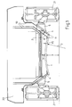
- the armored vehicle 20 shown in cross section in FIG a drive 21 is concave on its underside trained plate 1 of thickness 15, which extends over the entire Underside extends and with the side flange plates 4 left and right connected is.
- the concave formation is expressed in a radius 7.
- the structure is provided with respect to the drive 21 that a Ground clearance 3 is formed between the plate 1 and the floor.
- Torsion spring bars 2 are at a distance 14 from the base plate 1 and run across the floor space from the support arm bearing housings 5 starting.
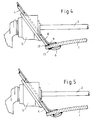
- FIGS. 3, 4, 5 show the detail of the connection of the flange plate 4 shown with the base plate 1.
- the tub side wall 8 is angled in its lower region 9 and bent and welded to the base plate 1.
- the flange plate 4 is in its lower area 6 also angled and with the grooved Welded base plate 18.
- the flange plate 4 takes that Support arm bearing housing 5 with the spring bar 2. Between support arm 2 and base plate 1 there is an intermediate distance 14.
- the base plate 1 is by means of the tub side wall 8 and flange plate 4 in the angled areas 6 and 9 on the top and bottom and also encompassed and welded on both sides left and right.
- the grooved bottom plate 1 is through with the above grooves Slits of the side plate 4 inserted and welded.
Landscapes
- Engineering & Computer Science (AREA)
- General Engineering & Computer Science (AREA)
- Aiming, Guidance, Guns With A Light Source, Armor, Camouflage, And Targets (AREA)
- Body Structure For Vehicles (AREA)
- Window Of Vehicle (AREA)
- Insulated Conductors (AREA)
Abstract
Description
Die Erfindung betrifft eine Vorrichtung zum Schutz gegen die Wirkung
einer Landmine, nach den im Oberbegriff des Patentanspruches 1
angegebenen Merkmalen.The invention relates to a device for protection against the action
a land mine, according to the in the preamble of
Die Erfindung bezieht sich dabei auf den Schutz von Personen in gepanzerten Fahrzeugen sowie auch das Fahrzeuggehäuse insgesamt gegen die Wirkung der Explosion von Minen, die auf oder im Erdboden verlegt sind.The invention relates to the protection of people in armored vehicles as well as the vehicle housing as a whole against the effect of the explosion of mines on or in the ground are misplaced.
Diese Fahrzeuge haben am Chassis in der Regel einen glatten Unterboden und eine möglichst hohe Bodenfreiheit zwischen Unterboden und Erdboden, die von entsprechend ausgebildeten Rad- oder Kettenfahrwerken sichergestellt wird, damit sich das Fahrzeug auch im Gelände möglichst ungehindert fortbewegen kann.These vehicles usually have a smooth underbody on the chassis and the highest possible ground clearance between the underbody and Soil made by appropriately trained bike or Chain chassis is ensured so that the vehicle is also in the Can move terrain as freely as possible.
Die brisante Druckwirkung der unter dem Fahrzeug explodierenden Mine wirkt auf den relativ großflächigen Fahrzeug- oder Wannenboden, verformt und beschädigt diesen und kann erhebliche Schäden im Fahrzeug verursachen.The explosive pressure effect of the mine exploding under the vehicle acts on the relatively large vehicle or tub floor, deformed and damages it and can cause significant damage to the vehicle cause.
Bisher sind folgende Vorrichtungen und Prinzipien für den Minenschutz bezüglich des Wannenbodens ausgeführt worden. Die einfachste Vorkehrung ist die Auslegung des Wannenbodens mit einer Plattendicke, die gegen eine vorgegebene Minenansprengung sicher ist.So far, the following devices and principles for mine protection regarding the tub floor. The easiest The precaution is to lay out the tub floor with a panel thickness, that is safe against a given mine attack.
Eine andere Möglichkeit liegt darin, die Bodenplatte einer Wanne mittels einer Sandwichplatte, die sich aus verschiedenen übereinanderliegenden Materialien aufbaut und die gegen eine vorgegebene Minenansprengung sicher ist, aufzubauen. Schließlich kann die Bodenstruktur aus übereinanderliegenden Platten und Hohlräumen, dabei auch zum Beispiel Luftschichten, ausgebildet sein, so dass die oberste Platte keine oder nur eine geringe Aufbeulung bei einer vorgegebenen Minenansprengung aufweist.Another option is to use the bottom plate of a tub a sandwich plate made up of different superimposed ones Builds up materials and against a predetermined mine demand is sure to build up. Finally, the floor structure can be made superimposed panels and cavities, including for example Air layers, be formed so that the top plate no or only a small bulge at a given mine demand having.
Nach dem Stand der Technik sind verschiedene Vorschläge zur Vermeidung von Beschädigungen gemacht worden.According to the prior art, there are various proposals for Avoidance of damage has been done.
Aus der DE 3119786 ist es bekannt, zum Schutz gegen Minen auf der Unterseite des Fahrzeugs flächige Panzerungselemente anzubringen.From DE 3119786 it is known to protect against mines on the Attach flat armor elements to the underside of the vehicle.
In der DE 19631715 ist der Fahrzeugboden mit einem keilförmig zum Boden ausgebildeten Deflektor ausgerüstet, wobei der Deflektor auch mit einem Gasgenerator ausgerüstet sein kann zur Abstützung von innen und Gegenwirkung gegen die Explosion.In DE 19631715 the vehicle floor is wedge-shaped Ground-trained deflector equipped, the deflector also with a gas generator can be equipped for support from the inside and Counteraction against the explosion.
In der DE 19653283 wird eine Raumzelle als Besatzungsraum im Fahrzeuggehäuse separat elastisch aufgehängt, um damit auch Schockwirkungen, die von außen auf das Fahrzeug wirken, in Bezug auf die Personen im Fahrzeug zu beseitigen.In DE 19653283 a room cell is used as the crew room in the Vehicle housing is separately suspended elastically in order to do so Shock effects that affect the vehicle from the outside in relation to to eliminate the people in the vehicle.
In weiteren Anmeldungen werden Verformungskörper am Fahrzeugboden angebracht, um die Druckwirkung von Minen auf das Fahrzeug zu vermindern.In further registrations, deformation bodies on the vehicle floor attached to the pressure effect of mines on the vehicle Reduce.
In der DE 19941928 werden Dämpfungselemente in einem Zwischenboden unter dem Fahrzeug vorgesehen, die die Minenwirkung mindern und aufnehmen sollen.In DE 19941928 damping elements are in an intermediate floor provided under the vehicle, which reduce the mine effect and should record.
Aufgabe der Erfindung ist es, ein gattungsgemäßes Schutzsystem auszubilden, daß eine ausreichende Schutzwirkung bei einfachem und robustem Aufbau für die Besatzung eines gepanzerten Fahrzeugs gewährleistet.The object of the invention is a generic protection system train that a sufficient protective effect with simple and robust construction for the crew of an armored vehicle guaranteed.
Diese Aufgabe wird erfindungsgemäß durch die kennzeichnenden
Merkmale des Anspruchs 1 gelöst.This object is achieved by the characterizing
Features of
Erfindungsgemäß wird der Wannenboden unter dem Fahrzeug aus einer konkav geformten Sandwichplatte (1) mit einer geeigneten Dicke und mit einem geeigneten Flächengewicht so hergestellt, dass eine geforderte Bodenfreiheit (3) gegeben ist bzw. erhalten bleibt. Oberhalb des Wannenbodens liegende Einbauten wie zum Beispiel die Federstäbe eines Drehstablaufwerkes werden so eingebaut, dass eine durch Minenexplosion auftretende Beulung im Bodenblech (1) diese Stäbe nicht erreicht und keine Beschädigungen hervorruft. Die Seitenflanschplatte (4) zur Aufnahme der Tragarmlagergehäuse (5) wird als abgewinkeltes Blech (6) unterhalb der Sandwichplatte (1) zusätzlich als tragendes Element und zur Erhöhung der Fahrzeugbodenstabilität herangezogen.According to the tub floor under the vehicle from one concave shaped sandwich plate (1) with a suitable thickness and with a suitable basis weight so that a required Ground clearance (3) is given or is maintained. Above the Built-in components such as the spring bars of a bathtub floor Torsion bar drive are installed so that one by mine explosion bulge occurring in the floor panel (1) does not reach these rods and causes no damage. The side flange plate (4) for Support arm bearing housing (5) is received as an angled plate (6) below the sandwich panel (1) also as a load-bearing element and for Increase in vehicle floor stability.
Die Vorteile der erfindungsgemässen Ausbildung des Fahrzeugbodens liegen insbesondere in der Einsparung von Bauraum und von Gewicht. Nach einer Mineneinwirkung sind Schäden einfacher zu beheben. Die Seitenflanschplatten stabilisieren den Fahrzeugboden und erhöhen die Festigkeit der gesamten Bodenkonstruktion. Weitere Vorteile ergeben sich aus den Unteransprüchen.The advantages of the design of the vehicle floor according to the invention are particularly in the saving of space and weight. Damage is easier to repair after exposure to a mine. The Side flange plates stabilize the vehicle floor and increase it Strength of the entire floor construction. There are further advantages from the subclaims.
Ausführungsbeispiele der Erfindung sind in den Zeichnungen schematisch dargestellt und werden im folgenden näher beschrieben. Es zeigen:
- Figur 1:
- einen Querschnitt eines Fahrzeugs mit Bodenschutz
- Figur 2:
- Ein Detail der Seitenansicht der Flanschplatte
- Figur 3:
- eine Detailansicht einer Verbindung von Flanschplatte und Bodenplatte im Querschnitt
- Figur 4:
- eine Detailansicht einer Verbindung von Flanschplatte und Bodenplatte als Querschnitt
- Figur 5:
- eine Detailansicht einer Verbindung von Flanschplatte und Bodenplatte als Querschnitt
- Figure 1:
- a cross section of a vehicle with floor protection
- Figure 2:
- A detail of the side view of the flange plate
- Figure 3:
- a detailed view of a connection of flange plate and base plate in cross section
- Figure 4:
- a detailed view of a connection of the flange plate and base plate as a cross section
- Figure 5:
- a detailed view of a connection of the flange plate and base plate as a cross section
Das der in Figur 1 im Querschnitt gezeigte gepanzerte Fahrzeug 20 mit
einem Laufwerk 21 wird an seiner Unterseite mit einer konkav
ausgebildeten Platte 1 der Dicke 15 bestückt, die sich über die gesamte
Unterseite erstreckt und mit den Seitenflanschplatten 4 links und rechts
verbunden ist. Die konkave Ausbildung drückt sich in einem Radius 7 aus.
Der Aufbau wird so vorgesehen in Bezug auf das Laufwerk 21, dass eine
Bodenfreiheit 3 zwischen Platte 1 und Boden ausgebildet wird.
Torsionsfederstäbe 2 liegen im Abstand 14 von der Bodenplatte 1 und
laufen quer durch den Bodenraum von den Tragarmlagergehäusen 5
ausgehend.The
In der Figur 2 wird die Seitenflanschplatte 4 gezeigt mit einer
Aufnahmebohrung 16 für das Tragarmlagergehäuse 5 und einer
Verschweißung 17 mit der Platte 1.In Figure 2, the
In den Figuren 3, 4, 5 wird das Detail der Verbindung der Flanschplatte 4
mit der Bodenplatte 1 gezeigt.FIGS. 3, 4, 5 show the detail of the connection of the
Die Wannenseitenwand 8 ist in ihrem unteren Bereich 9 abgewinkelt und
abgebogen und mit der Bodenplatte 1 verschweisst. Die Flanschplatte 4 ist
in ihrem unteren Bereich 6 ebenfalls abgewinkelt und mit der genuteten
Bodenplatte 18 verschweisst. Die Flanschplatte 4 nimmt das
Tragarmlagergehäuse 5 mit dem Federstab 2 auf. Zwischen Tragarm 2
und Bodenplatte 1 besteht ein Zwischenabstand 14.The
Die Bodenplatte 1 wird mittels Wannenseitenwand 8 und Flanschplatte 4 in
den abgewinkelten Bereichen 6 und 9 an der Oberseite und der Unterseite
und auch beidseitig links und rechts umfasst und verschweisst.The
Die genutete Bodenplatte 1 wird mit den vorstehenden Nuten durch
Schlitze der Seitenplatte 4 gesteckt und verschweißt. The
- 1
- Sandwichplatte / Bodenblech / Platte
- 2
- Torsionsfederstäbe / Tragarm
- 3
- Bodenfreiheit
- 4
- Seitenflanschplatte
- 5
- Tragarmlagergehäuse
- 6
- Blech / Bereich
- 7
- Radius
- 8
- Wannenseitenwand
- 8'
- Wannenseitenwand
- 9
- Bereich
- 10
- Doppelwandigkeit
- 11 12 13 14
- Abstand / Zwischenabstand
- 15
- Dicke
- 16
- Aufnahmebohrung
- 17
- Verschweißung
- 18
- Bodenplatte
- 19 20
- Fahrzeug
- 21
- Laufwerk
23
- 1
- Sandwich plate / floor plate / plate
- 2
- Torsion spring bars / support arm
- 3
- ground clearance
- 4
- Seitenflanschplatte
- 5
- Tragarmlagergehäuse
- 6
- Sheet / area
- 7
- radius
- 8th
- When sidewall
- 8th'
- When sidewall
- 9
- Area
- 10
- double wall
- 11 12 13 14
- Distance / intermediate distance
- 15
- thickness
- 16
- location hole
- 17
- welding
- 18
- baseplate
- 19 20
- vehicle
- 21
- drive
23
Claims (8)
dadurch gekennzeichnet, dass eine mit einem großen Radius (7) versehene konkave homogene Bodenschutzplatte (1) den Minenschutz bildet, wobei der Kreismittelpunkt des Radius unterhalb der Platte liegt.Device for protecting against the effects of a land mine, in particular for the crew of an armored vehicle by attaching protective elements to the vehicle floor,
characterized in that a concave homogeneous floor protection plate (1) provided with a large radius (7) forms the mine protection, the center of the circle of the radius being below the plate.
dadurch gekennzeichnet, dass Einbauteile oberhalb der Bodenschutzplatte (1) in der Wanne, zum Beispiel Torsionsfederstäbe, in einem freien Abstand (14) zur Bodenplatte eingebaut sind, so daß sie bei einer Minendetonation und Ausbildung einer dynamischen Beule in der Bodenplatte schadlos bleiben.Device according to claim 1,
characterized in that built-in parts above the floor protection plate (1) in the tub, for example torsion spring bars, are installed at a free distance (14) from the floor plate, so that they remain harmless in the event of mine detonation and the formation of a dynamic dent in the floor plate.
dadurch gekennzeichnet, dass die Bodenschutzplatte (1) einen mehrschichtigen Aufbau besitzt und / oder als Sandwichplatte ausgeführt ist.Device according to claims 1 and 2,
characterized in that the floor protection plate (1) has a multilayer structure and / or is designed as a sandwich plate.
dadurch gekennzeichnet, dass die für die Aufnahme von Tragarmlagergehäusen (5) erforderlichen Seitenflanschplatten (4) bis auf die Bodenplatte nach unten ragen und mit dieser verbunden sind oder diese mit einer Abwinkelung (9) nach unten umfassen und verbinden.Device according to one of claims 1 to 3,
characterized in that the side flange plates (4) required for receiving support arm bearing housings (5) protrude down to and are connected to the base plate or enclose and connect them with an angled portion (9) downwards.
dadurch gekennzeichnet, dass die Seitenflanschplatten (4) mit der Bodenplatte (1) mittels einer Verzahnung verbunden und verschweißt sind. Device according to claim 4,
characterized in that the side flange plates (4) are connected and welded to the base plate (1) by means of a toothing.
dadurch gekennzeichnet, dass die Seitenflanschplatten (4) mit der Bodenplatte (1) mittels Nut und Feder verzahnt und verschweisst sind.Device according to one of claims 4 or 5,
characterized in that the side flange plates (4) are toothed and welded to the base plate (1) by means of tongue and groove.
dadurch gekennzeichnet, dass die Wannenseitenwand (8) über Schweißverbindungen oder eine verschweißte Verzahnung oder eine verschweißte Nut-Feder-Verbindung mit der Bodenplatte (1) verbunden ist, wobei die Abwinkelung (9) wanneninnenseitig mit der Bodenplatte (1) verbunden ist.Device according to one of claims 1 to 6,
characterized in that the tub side wall (8) is connected to the base plate (1) via welded connections or a welded toothing or a welded tongue and groove connection, the bend (9) being connected to the base plate (1) on the inside of the tub.
dadurch gekennzeichnet, dass bei einer Doppelwandigkeit (10) der Wannenseitenwand 8 diese ebenfalls abgewinkelt und vernutet (11) mit der Bodenplatte (1) fest verbunden ist.Device according to one of claims 1 to 7,
characterized in that, in the case of a double wall (10), the tub side wall 8 is also angled and grooved (11) with the bottom plate (1) is firmly connected.
Applications Claiming Priority (2)
| Application Number | Priority Date | Filing Date | Title |
|---|---|---|---|
| DE10134394 | 2001-07-14 | ||
| DE10134394A DE10134394B4 (en) | 2001-07-14 | 2001-07-14 | Mine protection floor for an armored vehicle |
Publications (3)
| Publication Number | Publication Date |
|---|---|
| EP1275928A2 true EP1275928A2 (en) | 2003-01-15 |
| EP1275928A3 EP1275928A3 (en) | 2003-07-16 |
| EP1275928B1 EP1275928B1 (en) | 2004-03-17 |
Family
ID=7691872
Family Applications (1)
| Application Number | Title | Priority Date | Filing Date |
|---|---|---|---|
| EP02010537A Expired - Lifetime EP1275928B1 (en) | 2001-07-14 | 2002-05-10 | Vehicle floor for land-mine protection |
Country Status (6)
| Country | Link |
|---|---|
| US (1) | US6658984B2 (en) |
| EP (1) | EP1275928B1 (en) |
| AT (1) | ATE262158T1 (en) |
| DE (2) | DE10134394B4 (en) |
| IL (1) | IL150704A0 (en) |
| NO (1) | NO321498B1 (en) |
Cited By (11)
| Publication number | Priority date | Publication date | Assignee | Title |
|---|---|---|---|---|
| WO2004008062A1 (en) * | 2002-07-13 | 2004-01-22 | Ford Global Technologies, Llc | Armoured vehicle |
| EP1564520A3 (en) * | 2004-02-05 | 2005-08-24 | Steyr-Daimler-Puch Spezialfahrzeug AG & Co. KG | Hull structure of an armored vehicle with protection against landmines |
| EP1566607A1 (en) | 2004-02-18 | 2005-08-24 | Steyr-Daimler-Puch Spezialfahrzeug GmbH | Vehicle floor for land mine protection |
| FR2927990A1 (en) * | 2008-02-25 | 2009-08-28 | Nexter Systems Sarl | Shielded cab for e.g. vehicle, has assembly of shape concordant units providing mutual support point that supports wall with respect to floor when external mechanical effort is applied to wall and floor |
| WO2009102364A3 (en) * | 2007-11-16 | 2009-11-12 | Bae Systems Tactical Vehicle Systems Lp | Armored cab for vehicles |
| WO2012070996A1 (en) * | 2010-11-25 | 2012-05-31 | Bae Systems Bofors Ab | Mine protection accessory for wheeled vehicles |
| FR2974170A1 (en) * | 2011-04-15 | 2012-10-19 | Nexter Systems | Fabricated case for armored vehicle used in mines, has strip comprising longitudinal groove in which ankles are positioned, where ankles are spaced apart at regular interval and placed on portions of lateral wall apart from slot |
| EP2604970A1 (en) | 2011-12-16 | 2013-06-19 | NEXTER Systems | Armoured vehicle protected against explosive devices |
| EP2671665A1 (en) * | 2012-06-06 | 2013-12-11 | Renault Trucks Defense | Protective structure for vehicle, vehicle comprising such a structure and method for producing |
| EP2685205A1 (en) * | 2008-06-13 | 2014-01-15 | NEXTER Systems | Armored cab for a vehicle |
| WO2014184470A1 (en) * | 2013-05-15 | 2014-11-20 | Nexter Systems | Armoured vehicle body and floor structure for an armoured vehicle body |
Families Citing this family (62)
| Publication number | Priority date | Publication date | Assignee | Title |
|---|---|---|---|---|
| DE10117575A1 (en) * | 2001-04-07 | 2002-10-10 | Krauss Maffei Wegmann Gmbh & C | Device for protecting the crew of a military vehicle in the event of a mine explosion |
| AU2002953287A0 (en) * | 2002-12-12 | 2003-01-02 | Valir Pty Ltd | Protective apparatus for vehicles |
| DE102004006819B4 (en) * | 2004-02-11 | 2007-01-04 | Rheinmetall Landsysteme Gmbh | Vehicle with protection against the action of a landmine |
| FR2867554B1 (en) * | 2004-03-09 | 2006-08-25 | Giat Ind Sa | DEVICE FOR PROTECTING A MILITARY OR CIVIL VEHICLE AGAINST BREATH EFFECTS MINES. |
| US7770506B2 (en) * | 2004-06-11 | 2010-08-10 | Bae Systems Tactical Vehicle Systems Lp | Armored cab for vehicles |
| FR2873437B1 (en) * | 2004-07-23 | 2006-11-10 | Giat Ind Sa | DEVICE FOR PROTECTING A MILITARY OR CIVIL VEHICLE AGAINST MAGNETIC DETECTION MINES |
| GB2419567B (en) * | 2004-10-27 | 2008-04-09 | Constant Developments Ltd | A vehicle for use in mined areas |
| DE202005006655U1 (en) * | 2005-04-12 | 2005-08-25 | Drehtainer Gmbh Spezial Container- Und Fahrzeugbau | Protection for seated personnel in vessels and vehicles, where mines are present, has a suspended capsule with mountings which are released by explosion pressure waves to insulate the capsule from explosive forces |
| US7401540B1 (en) * | 2006-08-21 | 2008-07-22 | Robert William Kocher | Highly survivable urban utility vehicle (HSUUV) |
| EP1754949A1 (en) * | 2005-08-18 | 2007-02-21 | Mowag GmbH | Armoured vehicle |
| US20070186762A1 (en) * | 2005-12-22 | 2007-08-16 | Blackwater Lodge And Training Center Llc | Armored vehicle with blast deflecting hull |
| FR2897677B1 (en) * | 2006-02-17 | 2010-05-28 | Giat Ind Sa | DEVICE FOR PROTECTING A VEHICLE FLOOR |
| US8151685B2 (en) | 2006-09-15 | 2012-04-10 | Force Protection Industries, Inc. | Apparatus for defeating high energy projectiles |
| US20080066613A1 (en) * | 2006-09-15 | 2008-03-20 | Lockheed Martin Corporation | Perforated hull for vehicle blast shield |
| US20080173167A1 (en) * | 2006-09-15 | 2008-07-24 | Armor Holdings | Vehicular based mine blast energy mitigation structure |
| DE102006052609A1 (en) * | 2006-11-08 | 2008-05-15 | Krauss-Maffei Wegmann Gmbh & Co. Kg | Mine-protected, in particular military vehicle |
| US8418596B2 (en) | 2007-07-05 | 2013-04-16 | John J. Pavon | System and method for protecting vehicle occupants |
| US7908959B2 (en) | 2007-07-05 | 2011-03-22 | Pavon John J | System and method for protecting vehicle occupants |
| US8418597B2 (en) | 2007-07-05 | 2013-04-16 | John J. Pavon | System and method for protecting vehicle occupants |
| US20100212484A1 (en) * | 2007-09-26 | 2010-08-26 | Williams Raymond F | Method and apparatus for changing the trajectory of a projectile |
| US8052200B2 (en) * | 2007-10-31 | 2011-11-08 | Caterpillar Inc. | Vehicle cab floor protection system |
| IL198881A (en) * | 2008-05-29 | 2013-06-27 | Plasan Sasa Ltd | Belly system for a vehicle |
| US20120186428A1 (en) * | 2008-10-24 | 2012-07-26 | Gregory Lucas Peer | Blast energy absorption system |
| GB0822444D0 (en) | 2008-12-10 | 2009-01-14 | Sloman Roger M | Vehicle stabilization |
| US8033208B2 (en) * | 2009-04-10 | 2011-10-11 | Force Protection Technologies, Inc. | Mine resistant armored vehicle |
| US8146478B2 (en) * | 2009-04-10 | 2012-04-03 | Force Protection Technologies, Inc. | Mine resistant armored vehicle |
| DE102009033563A1 (en) * | 2009-07-16 | 2011-01-20 | Rheinmetall Landsysteme Gmbh | mine protection |
| US8490537B2 (en) | 2009-08-11 | 2013-07-23 | Sujoy Kumar Guha | Vehicle capable of dissipating explosion force and energy |
| DE102009053349B4 (en) * | 2009-11-17 | 2014-07-03 | Benteler Defense Gmbh & Co. Kg | Armored steel component |
| IL202275A0 (en) | 2009-11-23 | 2010-11-30 | Plasan Sasa Ltd | A system for providing protection against an explosive threat |
| EP2325595A3 (en) | 2009-11-23 | 2014-04-30 | Plasan Sasa Ltd. | Floor protection |
| US8499677B2 (en) | 2009-11-30 | 2013-08-06 | General Dynamics Land Systems—Canada Corporation | W-shaped hull |
| US8584572B2 (en) * | 2009-12-18 | 2013-11-19 | Hardwire, Llc | Vehicle with structural vent channels for blast energy and debris dissipation |
| US8578834B2 (en) * | 2009-12-18 | 2013-11-12 | Hardwire, Llc | Vehicle with structural vent channels for blast energy and debris dissipation |
| DE102010016605A1 (en) | 2010-04-23 | 2011-10-27 | Krauss-Maffei Wegmann Gmbh & Co. Kg | Floor pan of a vehicle, in particular an armored military vehicle, and additional armor for a floor pan |
| US8146477B2 (en) * | 2010-05-14 | 2012-04-03 | Force Protection Technologies, Inc. | System for protecting a vehicle from a mine |
| GB201008903D0 (en) | 2010-05-27 | 2010-07-14 | Sloman Roger M | Vehicle stabilization |
| US8413567B2 (en) * | 2010-06-23 | 2013-04-09 | International Truck Intellectual Property Company, Llc | Vehicle armor |
| CA2848227A1 (en) | 2011-09-07 | 2013-05-30 | Bae Systems Land & Armaments L.P. | Floating floor assembly for armored vehicles |
| US8998299B2 (en) * | 2011-09-09 | 2015-04-07 | Bae Systems Land & Armaments, L.P. | Armored vehicle with bolt-on bottom |
| USD966958S1 (en) | 2011-09-27 | 2022-10-18 | Oshkosh Corporation | Grille element |
| US9045014B1 (en) | 2012-03-26 | 2015-06-02 | Oshkosh Defense, Llc | Military vehicle |
| US8955859B1 (en) | 2011-09-27 | 2015-02-17 | Oshkosh Corporation | Isolated cab mounting system for an armored vehicle |
| WO2013115894A2 (en) | 2011-11-22 | 2013-08-08 | Bae Systems Survivabilty Systems, Llc | Armored cab for light tactical vehicles |
| CN102661681A (en) * | 2012-05-09 | 2012-09-12 | 内蒙古第一机械集团有限公司 | Anti-mine composite structure armored vehicle for carrying out multi-angle shunting on detonation waves |
| DE102012104307B4 (en) * | 2012-05-18 | 2014-05-08 | Krauss-Maffei Wegmann Gmbh & Co. Kg | Military motor vehicle |
| US8905164B1 (en) * | 2013-03-20 | 2014-12-09 | Us Government As Represented By The Secretary Of The Army | Vehicle with sacrificial underbody structure |
| US10323909B2 (en) * | 2013-11-27 | 2019-06-18 | Nederlandse Organisatie Voor Toegepast-Natuurwetenschappelijk Onderzoek Tno | Blast-protection element |
| US10184553B2 (en) * | 2014-02-12 | 2019-01-22 | Pratt & Miller Engineering and Fabrication, Inc. | Blast mitigating differential housing |
| CN109071193B (en) | 2016-04-08 | 2020-07-17 | 奥斯克什公司 | Leveling system for hoisting device |
| US10401128B2 (en) * | 2016-09-19 | 2019-09-03 | General Dynamics Land Systems | Systems and methods for underbody blast structure |
| US10845164B2 (en) | 2016-11-30 | 2020-11-24 | Bae Systems Land & Armaments L.P. | Blast mitigating restraint system |
| US20190310055A1 (en) * | 2018-04-09 | 2019-10-10 | Pratt & Miller Engineering and Fabrication, Inc. | Blast deflector |
| GB201911943D0 (en) | 2019-08-20 | 2019-10-02 | Advanced Blast & Ballistic Systems Ltd | Responding to an explosion local to an armoured vehicle |
| WO2021188207A2 (en) | 2020-01-29 | 2021-09-23 | Am General Llc | Armored cab for blast protection |
| DE102020114094A1 (en) | 2020-05-26 | 2021-12-02 | Benteler Automobiltechnik Gmbh | Vehicle armor |
| US11453444B2 (en) * | 2020-12-03 | 2022-09-27 | RV-De-Fender, LLC | Vehicle protection system to secure a protective covering to an axle of a vehicle |
| US11313652B1 (en) | 2021-02-25 | 2022-04-26 | Government Of The United States, As Represented By The Secretary Of The Army | Underbody kit |
| CN114572315A (en) * | 2022-03-31 | 2022-06-03 | 重庆望江工业有限公司 | Gradient type double-V-shaped mine-proof vehicle body structure |
| DE102022115403B3 (en) | 2022-06-21 | 2023-10-19 | Bayerische Motoren Werke Aktiengesellschaft | Arrangement of a protective plate in an underbody area of a special protection vehicle |
| CN115790278B (en) * | 2022-11-25 | 2025-06-10 | 中国人民解放军陆军工程大学 | Quick connection structure of conveniently preventing ground thunder board and armored vehicle chassis |
| US12448053B2 (en) | 2023-02-10 | 2025-10-21 | RV-De-Fender, LLC | Mechanism for securing a vehicle protection system and a backing plate of a brake assembly to an axle of a vehicle |
Citations (4)
| Publication number | Priority date | Publication date | Assignee | Title |
|---|---|---|---|---|
| DE3119786A1 (en) | 1981-05-19 | 1982-12-23 | Harry 7311 Hochdorf Apprich | DEVICE FOR SECURING SURFACES AGAINST THE EFFECT OF BLASTING BODIES |
| DE19631715A1 (en) | 1996-08-06 | 1998-02-12 | Bundesrep Deutschland | Vehicle protection system against landmines |
| DE19653283C1 (en) | 1996-12-20 | 1998-06-25 | Mak System Gmbh | Armored vehicle |
| DE19941928A1 (en) | 1999-09-03 | 2001-04-05 | Rheinmetall Landsysteme Gmbh | Device for protection against the effects of a land mine |
Family Cites Families (18)
| Publication number | Priority date | Publication date | Assignee | Title |
|---|---|---|---|---|
| US1136605A (en) * | 1914-11-21 | 1915-04-20 | John C Lobato | Motor-vehicle. |
| US1149127A (en) * | 1915-03-11 | 1915-08-03 | George Giem | Armored vehicle. |
| FR817908A (en) * | 1937-03-03 | 1937-09-14 | Battle tank hull | |
| US2382862A (en) * | 1942-04-15 | 1945-08-14 | Jr Augustine Davis | Armored car |
| FR1119078A (en) * | 1955-02-12 | 1956-06-14 | Tank | |
| BE587569A (en) * | 1959-03-24 | 1960-08-12 | Brevets Aero Mecaniques | Improvements to tracked vehicles, in particular to armored vehicles of this type |
| FR2453385A1 (en) * | 1979-04-06 | 1980-10-31 | Creusot Loire | Lightweight armoured vehicle - has heavily armoured central compartment for personnel engine and transmission, and lighter armoured cladding |
| CH634647A5 (en) * | 1978-12-04 | 1983-02-15 | Sulzer Ag | DOUBLE-WALLED TANK HOUSING. |
| FR2459445A1 (en) * | 1979-06-18 | 1981-01-09 | Legueu Paul | LIGHT VEHICLE OF RECOGNITION OR PATROL |
| FR2478295A1 (en) * | 1980-03-17 | 1981-09-18 | Legueu Paul | LIGHTWEIGHT RECONNAISSANCE AND PATROL VEHICLE |
| US4492282A (en) * | 1980-08-28 | 1985-01-08 | Cadillac Gage Company | Six-wheel armored vehicle |
| DE3206794A1 (en) | 1982-02-25 | 1983-09-01 | Hermann Dr.-Ing. 3302 Cremlingen Klaue | Armoured combat vehicle |
| DE3627485A1 (en) * | 1986-08-13 | 1988-02-18 | Bayerische Motoren Werke Ag | Lining element for motor vehicles |
| IT1290424B1 (en) * | 1995-10-25 | 1998-12-03 | Denel Pty Ltd | OVERLOCK KIT TO BE USED IN PROTECTING A PROTECTED AREA. |
| DE19635946A1 (en) * | 1996-09-05 | 1998-03-12 | Krauss Maffei Ag | Mine protection |
| DE19913845C2 (en) * | 1999-03-26 | 2002-06-13 | Henschel Wehrtechnik Gmbh | Device to ensure the availability of military vehicles |
| DE19935573B4 (en) * | 1999-07-31 | 2004-02-26 | Rheinmetall Landsysteme Gmbh | Device on vehicles, in particular on military tracked vehicles |
| DE19958594A1 (en) * | 1999-12-08 | 2001-06-21 | Trasco Fahrzeuge Bremen Gmbh | Vehicle armor-plated with several abutting armoring components has one armoring component provided with pin in abutting area of two such components and other armoring component provided with corresponding breakthrough |
-
2001
- 2001-07-14 DE DE10134394A patent/DE10134394B4/en not_active Expired - Fee Related
-
2002
- 2002-05-10 AT AT02010537T patent/ATE262158T1/en not_active IP Right Cessation
- 2002-05-10 EP EP02010537A patent/EP1275928B1/en not_active Expired - Lifetime
- 2002-05-10 NO NO20022225A patent/NO321498B1/en unknown
- 2002-05-10 DE DE50200296T patent/DE50200296D1/en not_active Expired - Lifetime
- 2002-07-11 IL IL15070402A patent/IL150704A0/en unknown
- 2002-07-12 US US10/193,147 patent/US6658984B2/en not_active Expired - Fee Related
Patent Citations (4)
| Publication number | Priority date | Publication date | Assignee | Title |
|---|---|---|---|---|
| DE3119786A1 (en) | 1981-05-19 | 1982-12-23 | Harry 7311 Hochdorf Apprich | DEVICE FOR SECURING SURFACES AGAINST THE EFFECT OF BLASTING BODIES |
| DE19631715A1 (en) | 1996-08-06 | 1998-02-12 | Bundesrep Deutschland | Vehicle protection system against landmines |
| DE19653283C1 (en) | 1996-12-20 | 1998-06-25 | Mak System Gmbh | Armored vehicle |
| DE19941928A1 (en) | 1999-09-03 | 2001-04-05 | Rheinmetall Landsysteme Gmbh | Device for protection against the effects of a land mine |
Cited By (17)
| Publication number | Priority date | Publication date | Assignee | Title |
|---|---|---|---|---|
| WO2004008062A1 (en) * | 2002-07-13 | 2004-01-22 | Ford Global Technologies, Llc | Armoured vehicle |
| EP1564520A3 (en) * | 2004-02-05 | 2005-08-24 | Steyr-Daimler-Puch Spezialfahrzeug AG & Co. KG | Hull structure of an armored vehicle with protection against landmines |
| EP1566607A1 (en) | 2004-02-18 | 2005-08-24 | Steyr-Daimler-Puch Spezialfahrzeug GmbH | Vehicle floor for land mine protection |
| WO2009102364A3 (en) * | 2007-11-16 | 2009-11-12 | Bae Systems Tactical Vehicle Systems Lp | Armored cab for vehicles |
| FR2927990A1 (en) * | 2008-02-25 | 2009-08-28 | Nexter Systems Sarl | Shielded cab for e.g. vehicle, has assembly of shape concordant units providing mutual support point that supports wall with respect to floor when external mechanical effort is applied to wall and floor |
| EP2685205A1 (en) * | 2008-06-13 | 2014-01-15 | NEXTER Systems | Armored cab for a vehicle |
| WO2012070996A1 (en) * | 2010-11-25 | 2012-05-31 | Bae Systems Bofors Ab | Mine protection accessory for wheeled vehicles |
| US8978537B2 (en) | 2010-11-25 | 2015-03-17 | Bae Systems Bofors Ab | Mine protection accessory for wheeled vehicles |
| FR2974170A1 (en) * | 2011-04-15 | 2012-10-19 | Nexter Systems | Fabricated case for armored vehicle used in mines, has strip comprising longitudinal groove in which ankles are positioned, where ankles are spaced apart at regular interval and placed on portions of lateral wall apart from slot |
| FR2984482A1 (en) * | 2011-12-16 | 2013-06-21 | Nexter Systems | ARMORED VEHICLE PROTECTS FROM EXPLOSIVE DEVICES |
| US8844970B2 (en) | 2011-12-16 | 2014-09-30 | Nexter Systems | Armored vehicle protected from explosive devices |
| EP2604970A1 (en) | 2011-12-16 | 2013-06-19 | NEXTER Systems | Armoured vehicle protected against explosive devices |
| FR2991765A1 (en) * | 2012-06-06 | 2013-12-13 | Renault Trucks Defense | STRUCTURAL PROTECTIVE ELEMENT FOR A VEHICLE, VEHICLE COMPRISING SUCH AN ELEMENT, AND METHOD OF MAKING SAME |
| EP2671665A1 (en) * | 2012-06-06 | 2013-12-11 | Renault Trucks Defense | Protective structure for vehicle, vehicle comprising such a structure and method for producing |
| WO2014184470A1 (en) * | 2013-05-15 | 2014-11-20 | Nexter Systems | Armoured vehicle body and floor structure for an armoured vehicle body |
| FR3005626A1 (en) * | 2013-05-15 | 2014-11-21 | Nexter Systems | ARMORED VEHICLE BODY AND FLOOR STRUCTURE FOR AN ARMORED VEHICLE BODY |
| EP2997324B1 (en) | 2013-05-15 | 2018-04-11 | NEXTER Systems | Floor structure for an armoured vehicle body |
Also Published As
| Publication number | Publication date |
|---|---|
| DE10134394A1 (en) | 2003-01-30 |
| EP1275928A3 (en) | 2003-07-16 |
| NO20022225D0 (en) | 2002-05-10 |
| EP1275928B1 (en) | 2004-03-17 |
| US6658984B2 (en) | 2003-12-09 |
| IL150704A0 (en) | 2003-02-12 |
| DE50200296D1 (en) | 2004-04-22 |
| NO20022225L (en) | 2003-01-15 |
| DE10134394B4 (en) | 2004-02-12 |
| ATE262158T1 (en) | 2004-04-15 |
| NO321498B1 (en) | 2006-05-15 |
| US20030010189A1 (en) | 2003-01-16 |
Similar Documents
| Publication | Publication Date | Title |
|---|---|---|
| EP1275928B1 (en) | Vehicle floor for land-mine protection | |
| EP1566607B1 (en) | Vehicle floor for land mine protection | |
| EP1564519B1 (en) | Vehicle with land mine protection | |
| EP2681504B1 (en) | Vehicle, especially military vehicle | |
| EP3012571B1 (en) | Vehicle floor pan comprising additional armouring | |
| EP1564518A1 (en) | Vehicle with land mine protection | |
| EP0828134B1 (en) | Protection from land mines | |
| WO2008135284A1 (en) | Construction machine | |
| EP1081452A2 (en) | Device for protection against land mines | |
| EP2650168B1 (en) | Housing, in particular vehicle housing protected against the effects of detonation | |
| DE112010000809T5 (en) | Damping suspension with the possibility of lifting for an additional reinforcement system | |
| DE19740103A1 (en) | Anti-mine protection device for vehicle | |
| DE19935573B4 (en) | Device on vehicles, in particular on military tracked vehicles | |
| EP2589919B1 (en) | Armoured vehicle exposed to danger from mines | |
| EP1182420A1 (en) | System for protecting a vehicle against the effects of an explosive charge | |
| DE19822201A1 (en) | Safety device for motor vehicles | |
| EP1182421B1 (en) | Protective system for a vehicle against the effects of an explosive device | |
| EP4045868B1 (en) | Underbody of a vehicle with mine protection | |
| EP3096108B1 (en) | Military vehicle | |
| DE202020102987U1 (en) | Vehicle with replaceable safety cladding for a driver's cab of the vehicle | |
| WO2026057642A1 (en) | Cab and utility vehicle | |
| WO2025256783A1 (en) | Commercial vehicle | |
| DE102024113829A1 (en) | Protective element for the body of a special protection vehicle and arrangement | |
| DE3601701A1 (en) | Armoured protective housing | |
| EP1900591A1 (en) | Locomotive with deformable part |
Legal Events
| Date | Code | Title | Description |
|---|---|---|---|
| PUAI | Public reference made under article 153(3) epc to a published international application that has entered the european phase |
Free format text: ORIGINAL CODE: 0009012 |
|
| AK | Designated contracting states |
Kind code of ref document: A2 Designated state(s): AT BE CH CY DE DK ES FI FR GB GR IE IT LI LU MC NL PT SE TR |
|
| AX | Request for extension of the european patent |
Free format text: AL;LT;LV;MK;RO;SI |
|
| PUAL | Search report despatched |
Free format text: ORIGINAL CODE: 0009013 |
|
| AK | Designated contracting states |
Designated state(s): AT BE CH CY DE DK ES FI FR GB GR IE IT LI LU MC NL PT SE TR |
|
| AX | Request for extension of the european patent |
Extension state: AL LT LV MK RO SI |
|
| 17P | Request for examination filed |
Effective date: 20030606 |
|
| GRAP | Despatch of communication of intention to grant a patent |
Free format text: ORIGINAL CODE: EPIDOSNIGR1 |
|
| GRAS | Grant fee paid |
Free format text: ORIGINAL CODE: EPIDOSNIGR3 |
|
| GRAA | (expected) grant |
Free format text: ORIGINAL CODE: 0009210 |
|
| AK | Designated contracting states |
Kind code of ref document: B1 Designated state(s): AT BE CH CY DE DK ES FI FR GB GR IE IT LI LU MC NL PT SE TR |
|
| PG25 | Lapsed in a contracting state [announced via postgrant information from national office to epo] |
Ref country code: TR Free format text: LAPSE BECAUSE OF FAILURE TO SUBMIT A TRANSLATION OF THE DESCRIPTION OR TO PAY THE FEE WITHIN THE PRESCRIBED TIME-LIMIT Effective date: 20040317 Ref country code: IT Free format text: LAPSE BECAUSE OF FAILURE TO SUBMIT A TRANSLATION OF THE DESCRIPTION OR TO PAY THE FEE WITHIN THE PRESCRIBED TIME-LIMIT;WARNING: LAPSES OF ITALIAN PATENTS WITH EFFECTIVE DATE BEFORE 2007 MAY HAVE OCCURRED AT ANY TIME BEFORE 2007. THE CORRECT EFFECTIVE DATE MAY BE DIFFERENT FROM THE ONE RECORDED. Effective date: 20040317 Ref country code: IE Free format text: LAPSE BECAUSE OF FAILURE TO SUBMIT A TRANSLATION OF THE DESCRIPTION OR TO PAY THE FEE WITHIN THE PRESCRIBED TIME-LIMIT Effective date: 20040317 Ref country code: NL Free format text: LAPSE BECAUSE OF FAILURE TO SUBMIT A TRANSLATION OF THE DESCRIPTION OR TO PAY THE FEE WITHIN THE PRESCRIBED TIME-LIMIT Effective date: 20040317 Ref country code: CY Free format text: LAPSE BECAUSE OF FAILURE TO SUBMIT A TRANSLATION OF THE DESCRIPTION OR TO PAY THE FEE WITHIN THE PRESCRIBED TIME-LIMIT Effective date: 20040317 Ref country code: FI Free format text: LAPSE BECAUSE OF FAILURE TO SUBMIT A TRANSLATION OF THE DESCRIPTION OR TO PAY THE FEE WITHIN THE PRESCRIBED TIME-LIMIT Effective date: 20040317 |
|
| REG | Reference to a national code |
Ref country code: GB Ref legal event code: FG4D Free format text: NOT ENGLISH |
|
| REG | Reference to a national code |
Ref country code: CH Ref legal event code: EP |
|
| AKX | Designation fees paid |
Designated state(s): AT BE CH CY DE DK ES FI FR GB GR IE IT LI LU MC NL PT SE TR |
|
| GBT | Gb: translation of ep patent filed (gb section 77(6)(a)/1977) |
Effective date: 20040317 |
|
| REG | Reference to a national code |
Ref country code: IE Ref legal event code: FG4D Free format text: GERMAN |
|
| REF | Corresponds to: |
Ref document number: 50200296 Country of ref document: DE Date of ref document: 20040422 Kind code of ref document: P |
|
| PG25 | Lapsed in a contracting state [announced via postgrant information from national office to epo] |
Ref country code: LU Free format text: LAPSE BECAUSE OF NON-PAYMENT OF DUE FEES Effective date: 20040510 Ref country code: AT Free format text: LAPSE BECAUSE OF NON-PAYMENT OF DUE FEES Effective date: 20040510 |
|
| PG25 | Lapsed in a contracting state [announced via postgrant information from national office to epo] |
Ref country code: MC Free format text: LAPSE BECAUSE OF NON-PAYMENT OF DUE FEES Effective date: 20040531 Ref country code: BE Free format text: LAPSE BECAUSE OF NON-PAYMENT OF DUE FEES Effective date: 20040531 |
|
| PG25 | Lapsed in a contracting state [announced via postgrant information from national office to epo] |
Ref country code: GR Free format text: LAPSE BECAUSE OF FAILURE TO SUBMIT A TRANSLATION OF THE DESCRIPTION OR TO PAY THE FEE WITHIN THE PRESCRIBED TIME-LIMIT Effective date: 20040617 Ref country code: DK Free format text: LAPSE BECAUSE OF FAILURE TO SUBMIT A TRANSLATION OF THE DESCRIPTION OR TO PAY THE FEE WITHIN THE PRESCRIBED TIME-LIMIT Effective date: 20040617 |
|
| PG25 | Lapsed in a contracting state [announced via postgrant information from national office to epo] |
Ref country code: ES Free format text: LAPSE BECAUSE OF FAILURE TO SUBMIT A TRANSLATION OF THE DESCRIPTION OR TO PAY THE FEE WITHIN THE PRESCRIBED TIME-LIMIT Effective date: 20040628 |
|
| REG | Reference to a national code |
Ref country code: SE Ref legal event code: TRGR |
|
| LTIE | Lt: invalidation of european patent or patent extension |
Effective date: 20040317 |
|
| NLV1 | Nl: lapsed or annulled due to failure to fulfill the requirements of art. 29p and 29m of the patents act | ||
| REG | Reference to a national code |
Ref country code: IE Ref legal event code: FD4D |
|
| ET | Fr: translation filed | ||
| BERE | Be: lapsed |
Owner name: RHEINMETALL LANDSYSTEME G.M.B.H. Effective date: 20040531 |
|
| PLBE | No opposition filed within time limit |
Free format text: ORIGINAL CODE: 0009261 |
|
| STAA | Information on the status of an ep patent application or granted ep patent |
Free format text: STATUS: NO OPPOSITION FILED WITHIN TIME LIMIT |
|
| 26N | No opposition filed |
Effective date: 20041220 |
|
| PG25 | Lapsed in a contracting state [announced via postgrant information from national office to epo] |
Ref country code: LI Free format text: LAPSE BECAUSE OF NON-PAYMENT OF DUE FEES Effective date: 20060531 Ref country code: CH Free format text: LAPSE BECAUSE OF NON-PAYMENT OF DUE FEES Effective date: 20060531 |
|
| REG | Reference to a national code |
Ref country code: CH Ref legal event code: PL |
|
| PG25 | Lapsed in a contracting state [announced via postgrant information from national office to epo] |
Ref country code: PT Free format text: LAPSE BECAUSE OF NON-PAYMENT OF DUE FEES Effective date: 20040817 |
|
| PGFP | Annual fee paid to national office [announced via postgrant information from national office to epo] |
Ref country code: SE Payment date: 20080513 Year of fee payment: 7 |
|
| PGFP | Annual fee paid to national office [announced via postgrant information from national office to epo] |
Ref country code: GB Payment date: 20080522 Year of fee payment: 7 |
|
| GBPC | Gb: european patent ceased through non-payment of renewal fee |
Effective date: 20090510 |
|
| REG | Reference to a national code |
Ref country code: FR Ref legal event code: ST Effective date: 20100129 |
|
| PG25 | Lapsed in a contracting state [announced via postgrant information from national office to epo] |
Ref country code: FR Free format text: LAPSE BECAUSE OF NON-PAYMENT OF DUE FEES Effective date: 20090602 |
|
| PGFP | Annual fee paid to national office [announced via postgrant information from national office to epo] |
Ref country code: FR Payment date: 20080526 Year of fee payment: 7 |
|
| PG25 | Lapsed in a contracting state [announced via postgrant information from national office to epo] |
Ref country code: GB Free format text: LAPSE BECAUSE OF NON-PAYMENT OF DUE FEES Effective date: 20090510 |
|
| PG25 | Lapsed in a contracting state [announced via postgrant information from national office to epo] |
Ref country code: SE Free format text: LAPSE BECAUSE OF NON-PAYMENT OF DUE FEES Effective date: 20090511 |
|
| PGFP | Annual fee paid to national office [announced via postgrant information from national office to epo] |
Ref country code: DE Payment date: 20210520 Year of fee payment: 20 |
|
| REG | Reference to a national code |
Ref country code: DE Ref legal event code: R071 Ref document number: 50200296 Country of ref document: DE |