EP1275950A2 - Dispositif de mesure d'une pression relative - Google Patents
Dispositif de mesure d'une pression relative Download PDFInfo
- Publication number
- EP1275950A2 EP1275950A2 EP02015428A EP02015428A EP1275950A2 EP 1275950 A2 EP1275950 A2 EP 1275950A2 EP 02015428 A EP02015428 A EP 02015428A EP 02015428 A EP02015428 A EP 02015428A EP 1275950 A2 EP1275950 A2 EP 1275950A2
- Authority
- EP
- European Patent Office
- Prior art keywords
- pressure
- housing
- measuring device
- carrier
- relative pressure
- Prior art date
- Legal status (The legal status is an assumption and is not a legal conclusion. Google has not performed a legal analysis and makes no representation as to the accuracy of the status listed.)
- Granted
Links
Images

Classifications
-
- G—PHYSICS
- G01—MEASURING; TESTING
- G01L—MEASURING FORCE, STRESS, TORQUE, WORK, MECHANICAL POWER, MECHANICAL EFFICIENCY, OR FLUID PRESSURE
- G01L19/00—Details of, or accessories for, apparatus for measuring steady or quasi-steady pressure of a fluent medium insofar as such details or accessories are not special to particular types of pressure gauges
- G01L19/06—Means for preventing overload or deleterious influence of the measured medium on the measuring device or vice versa
- G01L19/0627—Protection against aggressive medium in general
- G01L19/0645—Protection against aggressive medium in general using isolation membranes, specially adapted for protection
-
- G—PHYSICS
- G01—MEASURING; TESTING
- G01L—MEASURING FORCE, STRESS, TORQUE, WORK, MECHANICAL POWER, MECHANICAL EFFICIENCY, OR FLUID PRESSURE
- G01L19/00—Details of, or accessories for, apparatus for measuring steady or quasi-steady pressure of a fluent medium insofar as such details or accessories are not special to particular types of pressure gauges
- G01L19/0007—Fluidic connecting means
- G01L19/0038—Fluidic connecting means being part of the housing
Definitions
- the invention relates to a relative pressure measuring device.
- a pressure p to be measured is detected in relation to a reference pressure p R.
- the pressure measured in this way is referred to as the relative pressure.
- an atmospheric pressure that prevails in the vicinity of a measuring location serves as the reference pressure.
- Relative pressure gauges are used in almost all Industries used to measure relative pressures.
- the measured relative pressure values are e.g. to control, Regulate and / or monitor an industrial Manufacturing and / or processing process used.
- Relative pressure measuring devices have a relative pressure measuring cell installed in a housing.
- the relative pressure measuring cell has, for example, a base body and a pressure-sensitive element, for example a membrane, arranged thereon.
- the pressure p to be measured acts either directly or transmitted through a diaphragm seal on a side of the pressure-sensitive element facing away from the base body.
- the reference pressure p R acts on a side of the pressure-sensitive element facing the base body.
- the reference pressure p R is supplied to the pressure-sensitive element via a reference pressure supply, usually a bore penetrating the base body and opening into the housing.
- the relative pressure measuring cell is usually on one Carrier arranged through which the housing in a process-facing Half and a half facing away from the process is divided. Through the process-facing half the pressure p to be measured is supplied during operation. In the Process-opposite half is an electronic circuit for the recording, evaluation and / or processing of the Relative pressure measuring cell generated electrical signals arranged.
- the carrier preferably forms a pressure-resistant separation, which serves to escape a medium whose pressure to be measured to prevent.
- DE-690 15 367 T2 is a reference pressure measuring device described, which has a cylindrical support, the is enclosed in a cylindrical housing.
- the carrier is welded onto a process connection, which in the housing is screwed in. It is a reference pressure feed provided, which is led out laterally from the carrier, and on a side wall of the carrier facing the housing empties.
- this type of reference pressure supply is very complex because they have a large number of holes through the usually metallic carrier and the diaphragm seal required to build the piping system.
- the carrier consists of glass. It an electromechanical transducer is provided to do this serves a pressure-dependent change of the pressure sensitive element and capture in a convert pressure-dependent electrical quantity that over Connection lines is removable. With the connecting cables connected contact pins are glazed and in one Process-away half of the housing performed.
- an adapter is provided which is connected to the housing, and on the Meter housing is mounted.
- the carrier consists of a Isolator and the pressure sensitive element is immediate applied to the carrier.
- a hole in the housing Filter introduced, which serves to penetrate To prevent liquid and / or moisture.
- the bore is in the housing provide a cover that serves as splash protection.
- At least one Line section of the reference pressure supply a small Diameter and serves as a flame arrester.
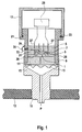
- Fig. 1 shows a section through an inventive Relativdruckmeß réelle.
- the relative pressure measuring device has one Relativtikmeßzelle 1, which is a pressure sensitive Element 3 has.
- the relative pressure measuring cell 1 is on a carrier 5 arranged.
- the relative pressure measuring cell 1 is e.g. a semiconductor sensor, e.g. a silicon chip with doped in Resistance elements.
- the silicon chip is here as Membrane is formed and forms the pressure sensitive Element 3. It is, as shown in Fig. 1, on a Base body 7 applied.
- the base body 7 is e.g. on Glass or silicon substrate.
- a pressure p to be measured is present on a process-facing side of the pressure-sensitive element 3.
- a relative pressure p R on a side facing away from the process, to which the pressure p to be measured is to be related.
- a pressure-dependent change in the pressure-sensitive element 3, here a deflection of the membrane, is thus determined by a relative pressure pp R acting on it.
- the carrier 5 on which the relative pressure measuring cell 1 is arranged is enclosed in a housing 9.
- the carrier 5 is in the illustrated embodiment disc-shaped and the housing 9 is cylindrical.
- the carrier 5 is made preferably made of glass. But they are also made of metal used.
- the housing 9 preferably consists of a Metal, e.g. made of steel or stainless steel.
- the carrier 5 is installed in a housing 9 such that the housing 9 in a first process-facing and one second half is turned away from the process.
- the carrier 5 preferably forms a pressure-resistant separation between the both halves.
- the pressure-sensitive element 3 is a diaphragm seal 11 connected, via which a pressure p to be measured on the Membrane 3 is transferred.
- the diaphragm seal 11 has one Separating membrane 13 on which the to be measured during operation Pressure p is present. He is as incompressible as possible Liquid, e.g. a silicone oil that filled one up an outer separation membrane 13 acting pressure to be measured p through a thin line onto the pressure-sensitive element 3 transmits.
- the line points preferably such a small diameter that the Line acts as a flame arrester.
- a process connection 15 provided at one end of the process-facing Housing 9 is connected.
- the process connection 15 in essential cylindrical component, which on the housing 9th is screwed on and at its end facing away from the housing External thread 10 is formed, which serves the Pressure sensor at a measuring location, e.g. an opening in a Container wall 12 to be fastened.
- the process connection 15 has a continuous central axial bore through which a medium during operation, whose pressure is to be measured to the separating membrane 13 of the diaphragm seal 11 arrives.
- the end of the housing 9 is a measuring device housing 17 arranged. Since the housing 9 through the carrier 5 in two completely separated halves, that can Measuring device housing 17 mounted directly on the housing 9 become.
- the housing 9 has an external thread 19 at the end to which the measuring device housing 17 is screwed on until it on a radially outward extending to the Housing 9 molded paragraph 21 rests. Between the Housing 9 and the meter housing 17 is a seal 23 provided that rests on paragraph 21.
- An electronic circuit is in the measuring device housing 17 25 proceed. This serves e.g. for recording and / or Processing of the relative pressure measuring cell 1 in operation generated electrical measurands.
- the relative pressure measuring cell 1 has an electromechanical one Converter, which serves a pressure-dependent change of the pressure-sensitive element 3, here a deflection of the Membrane, to record and into a pressure-dependent electrical Convert measured variable.
- the electromechanical converter shows preferably resistance elements doped into the membrane on whose electrical properties from on them mechanical influences. You can either individual resistors are used or it several resistors e.g. to a bridge circuit can be summarized, in which e.g. a pressure dependent Bridge voltage can be evaluated.
- the electrical size is via connecting lines 26, e.g. Bond wires, removable.
- the Connection lines 26 are through through the carrier 5 guided contact pins 27 connected.
- a metallic carrier e.g. Glass bushings can be provided.
- the provided carrier 5 made of glass are the contact pins 27 Glazed directly into the carrier 5 and facing away from the process Half of the housing 9 performed and there the electronic circuit 25 connected.
- a reference pressure supply is provided, through which the reference pressure p R is guided during operation to the side of the pressure-sensitive element 3 which is remote from the process.
- the reference pressure supply leads from a bore penetrating the base body 7 a bit in the direction away from the process into the carrier 5 and then laterally through the carrier 5 and a single bore 29 through the housing 9 completely out of the relative pressure measuring device.
- the bore penetrating the base body 7 has a first end on that in a by the pressure sensitive Element 3 and the body 7 formed chamber opens. A second end of the bore opens on the carrier 5.
- connection 31 through which the Bore in the base body 7 through the carrier 5 through is continued on the outside.
- the connection 31 can be a glass tube, or it can be one Recess can be provided in the glass.
- Such a recess e.g. through an appropriately shaped filling material manufactured after curing the glass from the Carrier 5 is removed.
- connection 31 is different from the prior art very simple structure. It has a maximum of two small ones straight holes but preferably only one recess or a glass tube. This is the Relative pressure supply very easy and inexpensive produced.
- a filter is preferably in the bore 29 in the housing 9 33, e.g. made of metal, polytetrafluoroethylene (PTFE) or introduced a hydrophilic material.
- the filter 33 serves for the penetration of liquid and / or To prevent moisture.
- the reference pressure supply leads directly from the housing 9 out. Even if the separating membrane 13 and that pressure sensitive element 3 destroyed by an accident no medium penetrates into the meter housing 17.
- the electronic circuit 25 is still protected and can give an error message or an alarm. This quickly detects the accident and the fault can be fixed before large amounts of medium escape.
- At least one line section has the Reference pressure supply, e.g. the hole through the body 7 or the connection 31, a small diameter and thereby serves as a flame arrester.
- Fig. 2 shows a further embodiment of a Relative pressure measuring device according to the invention. Due to the great agreement with the previous one In the following, only the exemplary embodiment existing differences explained in more detail.
- this is Housing 9 cylindrical.
- an adapter 37 e.g. by a weld 39, firmly connected.
- the Adapter 37 is exactly the same as that shown in FIG. 1 Embodiment mounted the meter housing. This offers two-part training with housing 9 and adapter 37 the advantage that different adapters are used can and thus mounted different types of measuring device can be made without changes to the Unit containing relative pressure measuring cell required are.
- a base body be used.
Landscapes
- Physics & Mathematics (AREA)
- General Physics & Mathematics (AREA)
- Measuring Fluid Pressure (AREA)
Applications Claiming Priority (2)
| Application Number | Priority Date | Filing Date | Title |
|---|---|---|---|
| DE10134359A DE10134359A1 (de) | 2001-07-14 | 2001-07-14 | Relativdruckmeßgerät |
| DE10134359 | 2001-07-14 |
Publications (3)
| Publication Number | Publication Date |
|---|---|
| EP1275950A2 true EP1275950A2 (fr) | 2003-01-15 |
| EP1275950A3 EP1275950A3 (fr) | 2005-07-20 |
| EP1275950B1 EP1275950B1 (fr) | 2007-09-12 |
Family
ID=7691844
Family Applications (1)
| Application Number | Title | Priority Date | Filing Date |
|---|---|---|---|
| EP02015428A Expired - Lifetime EP1275950B1 (fr) | 2001-07-14 | 2002-07-11 | Dispositif de mesure d'une pression relative |
Country Status (3)
| Country | Link |
|---|---|
| US (1) | US6752021B2 (fr) |
| EP (1) | EP1275950B1 (fr) |
| DE (2) | DE10134359A1 (fr) |
Cited By (3)
| Publication number | Priority date | Publication date | Assignee | Title |
|---|---|---|---|---|
| CN105899925A (zh) * | 2013-12-20 | 2016-08-24 | 恩德莱斯和豪瑟尔两合公司 | 相对压力传感器 |
| WO2021094232A1 (fr) * | 2019-11-13 | 2021-05-20 | Endress+Hauser SE+Co. KG | Capteur de pression pour déterminer la pression d'un milieu de traitement |
| WO2023110380A1 (fr) * | 2021-12-15 | 2023-06-22 | Endress+Hauser SE+Co. KG | Enregistreur de mesure de pression relative permettant de déterminer une première pression d'un milieu |
Families Citing this family (12)
| Publication number | Priority date | Publication date | Assignee | Title |
|---|---|---|---|---|
| DE10135568A1 (de) * | 2001-07-20 | 2003-02-06 | Endress & Hauser Gmbh & Co Kg | Drucksensor |
| DE10316033A1 (de) * | 2003-04-07 | 2004-10-21 | Endress + Hauser Gmbh + Co. Kg | Relativdruckmeßumformer |
| DE102007031980A1 (de) * | 2007-07-10 | 2009-01-15 | Robert Bosch Gmbh | Anschlusseinheit für eine Druckmesszelle |
| DE102010003709A1 (de) * | 2010-04-08 | 2011-10-13 | Endress + Hauser Gmbh + Co. Kg | Relativdrucksensor |
| DE102012109632A1 (de) | 2012-10-10 | 2014-04-10 | Endress + Hauser Gmbh + Co. Kg | Relativdruckmessaufnehmer |
| US9804002B2 (en) * | 2013-09-04 | 2017-10-31 | Cameron International Corporation | Integral sensor |
| DE102014107251A1 (de) | 2014-05-22 | 2015-11-26 | Endress + Hauser Gmbh + Co. Kg | Druckausgleichselement |
| DE102014108099A1 (de) * | 2014-06-10 | 2015-12-17 | Endress + Hauser Gmbh + Co. Kg | Drucksensor |
| DE202016105682U1 (de) | 2016-10-11 | 2016-11-29 | Endress+Hauser Gmbh+Co. Kg | Funktionaler Gehäusedeckel |
| DE102016124024A1 (de) * | 2016-12-12 | 2018-06-14 | Endress+Hauser SE+Co. KG | Drucksensor zur Ermittlung eines Differenzdruckes |
| DE102020126878A1 (de) | 2020-10-13 | 2022-04-14 | Vega Grieshaber Kg | Druckmesszelle und Verfahren zur Herstellung einer Druckmesszelle |
| DE102020133407A1 (de) | 2020-12-14 | 2022-06-15 | Endress+Hauser SE+Co. KG | Druckmessaufnehmer zur Bestimmung eines Relativdrucks |
Family Cites Families (12)
| Publication number | Priority date | Publication date | Assignee | Title |
|---|---|---|---|---|
| DE7933360U1 (de) * | 1979-11-27 | 1980-03-06 | Alpine Ag, 8900 Augsburg | Differenzdruckmessgeraet |
| DE8407322U1 (de) * | 1984-03-09 | 1984-05-30 | Keller, Hans W., Dipl.-Phys. ETH, 8404 Winterthur | Piezoresestive druckmesszelle |
| DE4023420A1 (de) * | 1990-07-24 | 1992-01-30 | Pfister Gmbh | Drucksensor |
| AT399234B (de) * | 1992-12-21 | 1995-04-25 | Vaillant Gmbh | Drucksensorik |
| DE29502825U1 (de) * | 1995-02-21 | 1996-06-20 | Keller AG für Druckmeßtechnik, Winterthur | Piezoresistiver Drucksensor oder Druckaufnehmer |
| DE19743749A1 (de) * | 1996-10-03 | 1998-04-09 | Hitachi Ltd | Halbleiterdrucksensor |
| DE19859507C2 (de) * | 1998-12-22 | 2003-04-24 | Wika Alexander Wiegand Gmbh | Kunststoffdruckmittler für Halbleiterindustrie |
| US6425291B1 (en) * | 1999-07-01 | 2002-07-30 | Endress + Hauser Gmbh + Co. | Relative-pressure sensor having a gas-filled bellows |
| EP1070948A1 (fr) * | 1999-07-20 | 2001-01-24 | Endress + Hauser Gmbh + Co. | Capteur de pression relative |
| DE10050300A1 (de) * | 2000-10-10 | 2002-04-11 | Endress Hauser Gmbh Co | Druckmeßzelle |
| DE10049996A1 (de) * | 2000-10-10 | 2002-04-11 | Endress Hauser Gmbh Co | Druckmessaufnehmer |
| US6581469B2 (en) * | 2001-01-12 | 2003-06-24 | Endress + Hauser Gmbh Co. | Differential pressure sensor and method of differential pressure measurement |
-
2001
- 2001-07-14 DE DE10134359A patent/DE10134359A1/de not_active Withdrawn
-
2002
- 2002-07-11 EP EP02015428A patent/EP1275950B1/fr not_active Expired - Lifetime
- 2002-07-11 DE DE50210870T patent/DE50210870D1/de not_active Expired - Fee Related
- 2002-07-15 US US10/195,148 patent/US6752021B2/en not_active Expired - Fee Related
Cited By (4)
| Publication number | Priority date | Publication date | Assignee | Title |
|---|---|---|---|---|
| CN105899925A (zh) * | 2013-12-20 | 2016-08-24 | 恩德莱斯和豪瑟尔两合公司 | 相对压力传感器 |
| CN105899925B (zh) * | 2013-12-20 | 2019-03-29 | 恩德莱斯和豪瑟尔欧洲两合公司 | 相对压力传感器 |
| WO2021094232A1 (fr) * | 2019-11-13 | 2021-05-20 | Endress+Hauser SE+Co. KG | Capteur de pression pour déterminer la pression d'un milieu de traitement |
| WO2023110380A1 (fr) * | 2021-12-15 | 2023-06-22 | Endress+Hauser SE+Co. KG | Enregistreur de mesure de pression relative permettant de déterminer une première pression d'un milieu |
Also Published As
| Publication number | Publication date |
|---|---|
| EP1275950A3 (fr) | 2005-07-20 |
| DE50210870D1 (de) | 2007-10-25 |
| US20030024321A1 (en) | 2003-02-06 |
| EP1275950B1 (fr) | 2007-09-12 |
| DE10134359A1 (de) | 2003-02-06 |
| US6752021B2 (en) | 2004-06-22 |
Similar Documents
| Publication | Publication Date | Title |
|---|---|---|
| EP1275950B1 (fr) | Dispositif de mesure d'une pression relative | |
| DE2237535C2 (de) | Druckwandler | |
| EP1128172B1 (fr) | Capteur de pression | |
| EP1409979B1 (fr) | Capteur de pression | |
| DE69023930T2 (de) | Messwertgeber mit ausgedehnter messfähigkeit und anteilig nutzbare mittel zum überlastungsschutz. | |
| EP0135653A2 (fr) | Capteur de pression et/ou de température | |
| EP2823274B1 (fr) | Élément de mesure micromécanique | |
| EP1425563B1 (fr) | Appareil de mesure de pression | |
| EP2464955B1 (fr) | Capteur de pression relative | |
| WO2013160019A2 (fr) | Capteur de mesure de pression | |
| DE4201634C2 (de) | Halbleiter-Druckaufnahmevorrichtung | |
| EP3146303A1 (fr) | Élément de compensation de pression | |
| DE202009014795U1 (de) | Druckmessmodul | |
| EP1611422A2 (fr) | Convertisseur de mesure de pression relative | |
| DE102012109632A1 (de) | Relativdruckmessaufnehmer | |
| DE10221219A1 (de) | Drucksensor | |
| DE102006040325A1 (de) | Vorrichtung zur Überwachung der Dichtigkeit von Fügestellen bei einem Druckmessgerät | |
| WO2023110380A1 (fr) | Enregistreur de mesure de pression relative permettant de déterminer une première pression d'un milieu | |
| EP3237866B1 (fr) | Convertisseur de pression et procédé permettant de faire fonctionner ledit convertisseur | |
| EP1710545A1 (fr) | Capteur muni d'un dispositif de protection contre les surpressions | |
| DE202013002475U1 (de) | Druckaufnehmer | |
| WO2021094232A1 (fr) | Capteur de pression pour déterminer la pression d'un milieu de traitement | |
| DE102019133816A1 (de) | Drucksensor zum Bestimmen einer Relativdruckgröße | |
| DE102014214866A1 (de) | Drucksensor | |
| DE102023209101A1 (de) | Medienrobuster Sensor |
Legal Events
| Date | Code | Title | Description |
|---|---|---|---|
| PUAI | Public reference made under article 153(3) epc to a published international application that has entered the european phase |
Free format text: ORIGINAL CODE: 0009012 |
|
| AK | Designated contracting states |
Kind code of ref document: A2 Designated state(s): AT BE BG CH CY CZ DE DK EE ES FI FR GB GR IE IT LI LU MC NL PT SE SK TR |
|
| AX | Request for extension of the european patent |
Free format text: AL;LT;LV;MK;RO;SI |
|
| PUAL | Search report despatched |
Free format text: ORIGINAL CODE: 0009013 |
|
| AK | Designated contracting states |
Kind code of ref document: A3 Designated state(s): AT BE BG CH CY CZ DE DK EE ES FI FR GB GR IE IT LI LU MC NL PT SE SK TR |
|
| AX | Request for extension of the european patent |
Extension state: AL LT LV MK RO SI |
|
| RIC1 | Information provided on ipc code assigned before grant |
Ipc: 7G 01L 19/14 A |
|
| 17P | Request for examination filed |
Effective date: 20050816 |
|
| AKX | Designation fees paid |
Designated state(s): DE FR GB IT |
|
| GRAP | Despatch of communication of intention to grant a patent |
Free format text: ORIGINAL CODE: EPIDOSNIGR1 |
|
| GRAS | Grant fee paid |
Free format text: ORIGINAL CODE: EPIDOSNIGR3 |
|
| GRAA | (expected) grant |
Free format text: ORIGINAL CODE: 0009210 |
|
| AK | Designated contracting states |
Kind code of ref document: B1 Designated state(s): DE FR GB IT |
|
| REG | Reference to a national code |
Ref country code: GB Ref legal event code: FG4D Free format text: NOT ENGLISH |
|
| REF | Corresponds to: |
Ref document number: 50210870 Country of ref document: DE Date of ref document: 20071025 Kind code of ref document: P |
|
| GBV | Gb: ep patent (uk) treated as always having been void in accordance with gb section 77(7)/1977 [no translation filed] | ||
| PG25 | Lapsed in a contracting state [announced via postgrant information from national office to epo] |
Ref country code: GB Free format text: LAPSE BECAUSE OF FAILURE TO SUBMIT A TRANSLATION OF THE DESCRIPTION OR TO PAY THE FEE WITHIN THE PRESCRIBED TIME-LIMIT Effective date: 20070912 |
|
| PLBE | No opposition filed within time limit |
Free format text: ORIGINAL CODE: 0009261 |
|
| STAA | Information on the status of an ep patent application or granted ep patent |
Free format text: STATUS: NO OPPOSITION FILED WITHIN TIME LIMIT |
|
| 26N | No opposition filed |
Effective date: 20080613 |
|
| PGFP | Annual fee paid to national office [announced via postgrant information from national office to epo] |
Ref country code: DE Payment date: 20080722 Year of fee payment: 7 |
|
| PG25 | Lapsed in a contracting state [announced via postgrant information from national office to epo] |
Ref country code: DE Free format text: LAPSE BECAUSE OF NON-PAYMENT OF DUE FEES Effective date: 20100202 |
|
| PG25 | Lapsed in a contracting state [announced via postgrant information from national office to epo] |
Ref country code: IT Free format text: LAPSE BECAUSE OF NON-PAYMENT OF DUE FEES Effective date: 20080731 |
|
| PG25 | Lapsed in a contracting state [announced via postgrant information from national office to epo] |
Ref country code: FR Free format text: LAPSE BECAUSE OF FAILURE TO SUBMIT A TRANSLATION OF THE DESCRIPTION OR TO PAY THE FEE WITHIN THE PRESCRIBED TIME-LIMIT Effective date: 20070912 |