EP1275972A2 - Assemblage de bobines à haute fréquence pour un appareil à résonance magnétique - Google Patents
Assemblage de bobines à haute fréquence pour un appareil à résonance magnétique Download PDFInfo
- Publication number
- EP1275972A2 EP1275972A2 EP02100803A EP02100803A EP1275972A2 EP 1275972 A2 EP1275972 A2 EP 1275972A2 EP 02100803 A EP02100803 A EP 02100803A EP 02100803 A EP02100803 A EP 02100803A EP 1275972 A2 EP1275972 A2 EP 1275972A2
- Authority
- EP
- European Patent Office
- Prior art keywords
- patient
- elements
- coil arrangement
- frequency
- resonator
- Prior art date
- Legal status (The legal status is an assumption and is not a legal conclusion. Google has not performed a legal analysis and makes no representation as to the accuracy of the status listed.)
- Withdrawn
Links
Images
Classifications
-
- G—PHYSICS
- G01—MEASURING; TESTING
- G01R—MEASURING ELECTRIC VARIABLES; MEASURING MAGNETIC VARIABLES
- G01R33/00—Arrangements or instruments for measuring magnetic variables
- G01R33/20—Arrangements or instruments for measuring magnetic variables involving magnetic resonance
- G01R33/28—Details of apparatus provided for in groups G01R33/44 - G01R33/64
- G01R33/32—Excitation or detection systems, e.g. using radio frequency signals
- G01R33/34—Constructional details, e.g. resonators, specially adapted to MR
- G01R33/341—Constructional details, e.g. resonators, specially adapted to MR comprising surface coils
- G01R33/3415—Constructional details, e.g. resonators, specially adapted to MR comprising surface coils comprising arrays of sub-coils, i.e. phased-array coils with flexible receiver channels
Definitions
- the invention relates to a high-frequency coil arrangement for an open MR device a plurality of resonator elements in the range of one in the examination volume an MRI patient can be arranged, the resonator elements consist of at least one conductor element and at least one capacitor.
- the nuclear magnetization is localized within the Examination volume using spatially inhomogeneous magnetic fields that change over time (Magnetic field gradient), which is superimposed on a static magnetic field that is as homogeneous as possible are.
- Magnetic field gradient spatially inhomogeneous magnetic fields that change over time
- the nuclear spin signal is used as the voltage in the high-frequency coil arrangement of the MR device is induced under the influence of a suitable one Sequence of high-frequency and gradient pulses recorded in the time domain.
- the actual image reconstruction is then carried out by Fourier transformation Time signals. By the number, the time interval, the duration and the strength of the used Gradient pulses are given by scanning the reciprocal k-space which the volume area to be imaged (FOV, "field of view”) and the image resolution are determined.
- FOV reciprocal k-space which the volume area to be imaged
- the number of images is determined by requirements for the image size and image resolution Phase coding steps and thus the duration of the imaging sequence are predetermined. at Modern MR devices will produce images with the highest possible quality aimed for a short time. This places special demands on the gradient - and the high frequency system of the MR devices.
- a transmitting and receiving coil such as an integrated body coil (body coil), which can be used for volume imaging of the examination volume.
- body coil integrated body coil
- cage resonators birdcage coils
- Conductor rods running parallel to the main field direction, which on the end faces of the coil are connected to one another via ring conductors.
- the resonance behavior of the body coil is determined by capacitor elements through which the conductor elements form a network are connected.
- the static magnetic field is usually horizontal aligned and runs parallel to the longitudinal axis of the cylindrical coil arrangement.
- the Cylindrical configuration allows high field strengths with well controllable Generate field distribution.
- the disadvantage is that access to the examination volume with the patient in it is severely restricted. Through the cylindrical geometry are interventional studies because of bad Accessibility of the patient is made difficult or even impossible. The narrowness of the The closed cylindrical tube of the MR device also often triggers when Patients from claustrophobic reactions.
- open MR devices have been used recently developed in which the examination volume for both the patient and an examining doctor is open and easily accessible.
- Some of the open MR devices use two disc - shaped magnetic elements on opposite sides of the Examination volume are arranged and a vertically aligned, static magnetic field produce.
- the coils are used to generate the magnetic field gradients and the high-frequency coils are usually flat and disk-shaped and integrated into the pole faces of the main field magnet.
- the flat design of the high-frequency coil arrangement with open MR devices has again the disadvantage that it is difficult to have a sufficiently homogeneous high-frequency field to generate in the study volume.
- There are particularly strong inhomogeneities in the proximity of the pole faces into which the conductor elements of the high-frequency coils are integrated are.
- Another problem is that with open MR devices, unlike the conventional systems, around the side of the examination volume there is no radio frequency shielding. For this reason, the high frequency field strength drops outside of the examination volume only slowly and also the spatial Sensitivity profile in the detection extends in areas far outside the Examination volume. This means that outside the area of interest MR signals are generated that are due to refolding effects (aliasing) undesirably become visible as artifacts in the selected FOV of the generated image.
- cage resonators birdscage coils
- open MR devices have cage resonators (birdcage coils) that are arranged around the patient. This is because they generate a circular polarized radio frequency field in a vertical plane. Is required due to the vertical aligned static magnetic field, however, a perpendicular to it, horizontally aligned RF field.
- the object of the present invention is a high-frequency coil arrangement to be made available for open MR devices where this is in transmission mode generated high-frequency field and also the spatial sensitivity profile in the Detection are limited as closely as possible to the volume of interest of interest. It should have a high sensitivity in the detection and it should in particular be possible high enough radio frequency field strengths for the requirements of the imaging to generate with acceptable load for the patient.
- This task is in a high-frequency coil arrangement of the aforementioned Art solved in that at least one of the resonator elements is a solenoid element is, the conductor element at least one open, guided around the patient Swirl forms.
- the solenoid elements In contrast to the flat high-frequency coils integrated in the pole faces of the magnet the solenoid elements have a spatial sensitivity profile that is more or less is less restricted to the area of the patient to be examined. If the Windings of the solenoid elements are closely guided around the patient, affects this positively affects the signal-to-noise ratio. It also only becomes comparatively low Transmission power is required to excite MR signals.
- the individual resonator elements of the invention Assign separate receiver channels to the coil arrangement, via which the detected MR signals be transmitted to a receiving unit for further processing. So there is on the one hand the possibility of combining the individual resonator elements detected MR signals to perform volume imaging with the largest possible FOV. Alternatively, partial images can be generated from the separately detected MR signals which are then combined to form an overall picture. This can on the one hand be advantageous for improving the signal-to-noise ratio, the individual Resonator elements are used as synergy coils. There is also the possibility that Individual images on the basis of those assigned to the individual resonator elements spatial sensitivity profiles to combine with each other in imaging Saving measurement time (SENSE method, sensitivity encoding). It is advantageous that the well-defined spatial sensitivity profiles of the solenoid elements are used can be.
- the level in the high-frequency coil arrangement according to the invention at least one solenoid element according to claim 2 perpendicular to the longitudinal axis of the Align patients.
- an advantageous embodiment of the coil arrangement according to claim 3 can be realized in which a plurality of solenoid elements with variable winding circumference are arranged axially one behind the other.
- a large FOV can be covered by the relevant regions of interest of the Individual solenoid elements enclose patients.
- the winding size is adjusted to the circumference of the patient, placing each turn closely around the patient In this way, the sensitive area becomes narrow to those of interest Regions, which has an advantageous effect on the image quality.
- At least one of the resonator elements is a surface coil, which is oriented such that the high-frequency magnetic field generated by the surface coil has a component perpendicular to the longitudinal axis of the patient.
- the Surface coil in an open MR device for optimal sensitivity be aligned that by the nuclear magnetization precessing in the horizontal plane a detectable voltage is induced especially when the level of the used Surface coil aligned perpendicular to the solenoid elements differ the spatial sensitivity profiles of the resonator elements in question differ greatly, which is advantageous for image reconstruction using the SENSE method.
- the individual resonator elements of the invention should High-frequency coil arrangement can be uncovered from each other. This can be special simply according to claim 5 by means of capacitors arranged between the conductor elements or inductors. By suitably dimensioning the capacity or Inductance values must ensure that there is no resonant coupling between the different resonator elements. It may be useful to use decoupling networks (consisting of capacitors and inductors) between the conductor elements to provide both adjacent and more distant resonator elements.
- the coil arrangement according to the invention can with an open MR device according to the Claims 6 and 7 are used. It is used to carry out parallel Imaging method (SYNERGY, SENSE) expediently every resonator element a separate receiving channel is assigned to the receiving unit.
- parallel Imaging method SYNERGY, SENSE
- each resonator element is assigned a separate transmission channel of a transmission unit is, by means of the transmission unit for each resonator element, the phase and / or The amplitude of the high-frequency feed can be specified individually.
- each resonator element in the open MR device according to the invention is assigned to a separate transmission channel, the field distribution in the examination volume advantageously fully controllable. Because it is possible, every conceivable Current distribution in the arrangement of the conductor elements by specifying the amplitude and Generate phase on the individual transmission channels. Also the timing of the high-frequency feed can be specified differently on each transmission channel become. The amplitude and the phase of each individual transmission channel can be determined by the Software of the MR device can be controlled, which is a direct interactive control of the Field distribution (RF shimming). For example, a fully automatic one is conceivable Regulation of the high-frequency field homogeneity in the examination volume in the Integrate imaging sequence to change influences on field distribution, such as for example, by the different dielectric properties of the examined Patients to compensate.
- This version has the advantage that only a single power transmitter is required for high-frequency radiation, the Output signal distributed to the individual resonator elements using the combiner hybrid becomes. The distribution is expediently carried out in such a way that in the examination volume the most homogeneous possible high-frequency field distribution is generated.
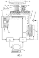
- an open magnet with a upper pole plate 100 and a lower pole plate 101. Between the two pole plates 100,101 is the examination volume in which there is no closer to one shown patient table is a patient 102. In the area of the examination volume becomes a vertically directed, static magnetic field with a strength of, for example 0.7 Tesla generated. For MR imaging, the examination volume must also time-varying magnetic field gradients are generated. Several gradient coils are used for this 103, which are integrated into the pole disks 100, 101 of the open magnet.
- the for MR imaging which is also required, generates high-frequency fields by means of an arrangement of high-frequency coils made according to the invention from ten solenoid elements 104, the conductor elements of which are guided around the patient, form open turns.
- the solenoid elements 104 are not shown Capacitors integrated, which determines the resonance behavior of the arrangement.
- In 1 shows two groups of solenoid elements. To the chest of the Patients 102 have five turns with a correspondingly large circumference. The turns around the patient's head are corresponding to the lesser Circumference of the head smaller. One comes in the area of the skull cap of patient 102 particularly small winding for use Except for excitation of MR signals in the examination volume the coil arrangement shown is also used for its detection.
- Each of the ten solenoid elements 104 shown in FIG. 1 stands with one Switch S / R in connection by the resonator element 104 in question depending on Operating mode is connected to one of two possible connections.
- the one for the Broadcasting specific connections are numbered 1-10 for receiving provided connections with the lower case letters a-j.
- the connections 1-10 are the outputs of a transmission unit 105 provided with the corresponding numbers assigned. This has one for each individual resonator element of the coil arrangement own transmission channel, each of which has a power amplifier 106 and a high-frequency control unit 107 has.
- the amplitude is determined by means of the high-frequency control units 107 and the phase of the high-frequency signal can be set individually for each individual transmission channel, so that almost any high-frequency field distribution in the examination volume of the MR device can be generated.
- a distribution network 108 (combiner hybrid) through which the output signal a high-frequency transmitter amplifier 109 is distributed to the connections 1-10, whereby, through the combiner hybrid 108 for each output channel 1-10 the amplitude and Phase of the high-frequency signal is set.
- the transmission unit 105 or the transmission amplifier 109 is in the investigation volume with a control unit 110 in connection.
- To control the chronological order of the The control unit 110 is also gradient pulses with the gradient coil arrangement 103 connected.
- the connections a-j intended for reception are receiving channels of a receiving unit 111 denoted by the corresponding letters assigned. Each receive channel is with a sensitive high frequency preamplifier 112 and equipped with a demodulator 113.
- the receiving unit 111 registered MR signals are transmitted to a reconstruction unit 114, where the digitized signals can be combined and Fourier analyzed.
- the means of Reconstruction unit 114 generated images are then displayed on the monitor Microcomputers 115 output.
- the microcomputer 115 is also used for control of the MR device by a user, for which purpose the computer 115 also uses the Control unit 110 is connected.
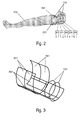
- FIG. 2 shows an arrangement of around the head that is optimized for head / neck imaging
- Patient 102 passed solenoid elements 104.
- the circumference of turns 104 is adapted to the circumference of the patient's head, neck and shoulders, to the sensitive volume of the arrangement as closely as possible to the interested Restrict regions of the patient to be examined 102.
- the turns are supported on the body of the patient 102 by a holding device 201.
- the individual solenoid elements 104 are connected to separate reception channels f-j, can complete volume imaging by combining the respectively detected MR signals the head-neck-shoulder area.
- FIG. 3 shows an alternative coil arrangement for head / neck imaging. This exists alongside those around the neck of the patient, not shown here Solenoid elements 104 made of surface coils 301 arranged laterally on the head, which generate a radio frequency field that has horizontally aligned components, that is run perpendicular to the main field of the open MR device.
- the neck area shows the Coil arrangement shown on surface coils 302, which are interconnected as butterfly coils are, and thus interacting, also substantially horizontal generate directed field.
- the coil arrangement shown is based on the anatomy of the patient adjusted so that imaging of the head and neck region with high resolution and high S / N ratio in open MR systems is possible. In use corresponds to such an arrangement the head coils in conventional MR devices, which are usually there are designed as cage resonators (birdcage coils).
Landscapes
- Physics & Mathematics (AREA)
- Condensed Matter Physics & Semiconductors (AREA)
- General Physics & Mathematics (AREA)
- Magnetic Resonance Imaging Apparatus (AREA)
Applications Claiming Priority (2)
| Application Number | Priority Date | Filing Date | Title |
|---|---|---|---|
| DE10134171 | 2001-07-13 | ||
| DE10134171A DE10134171A1 (de) | 2001-07-13 | 2001-07-13 | Hochfrequenz-Spulenanordnung für ein MR-Gerät |
Publications (2)
| Publication Number | Publication Date |
|---|---|
| EP1275972A2 true EP1275972A2 (fr) | 2003-01-15 |
| EP1275972A3 EP1275972A3 (fr) | 2004-04-21 |
Family
ID=7691722
Family Applications (1)
| Application Number | Title | Priority Date | Filing Date |
|---|---|---|---|
| EP02100803A Withdrawn EP1275972A3 (fr) | 2001-07-13 | 2002-07-12 | Assemblage de bobines à haute fréquence pour un appareil à résonance magnétique |
Country Status (4)
| Country | Link |
|---|---|
| US (1) | US6650118B2 (fr) |
| EP (1) | EP1275972A3 (fr) |
| JP (1) | JP2003038459A (fr) |
| DE (1) | DE10134171A1 (fr) |
Families Citing this family (26)
| Publication number | Priority date | Publication date | Assignee | Title |
|---|---|---|---|---|
| DE10124465A1 (de) * | 2001-05-19 | 2002-11-21 | Philips Corp Intellectual Pty | Sende- und Empfangsspule für MR-Gerät |
| US20060261811A1 (en) * | 2002-12-06 | 2006-11-23 | Ham Cornelis L G | Magnetic resonance imaging system with a plurality of transmit coils |
| EP1599741A1 (fr) * | 2003-02-28 | 2005-11-30 | Koninklijke Philips Electronics N.V. | Irm a table mobile et a sous-echantillonnage |
| JP4607430B2 (ja) * | 2003-03-28 | 2011-01-05 | ジーイー・メディカル・システムズ・グローバル・テクノロジー・カンパニー・エルエルシー | Rfコイルおよび磁気共鳴撮影装置 |
| US6806708B1 (en) * | 2003-06-17 | 2004-10-19 | The Board Of Trustees Of The Leland Standford Junior University | Multi-coil reconstruction of MRI signals using linear phase multiplied data with separate demodulators for each coil |
| WO2005034141A2 (fr) * | 2003-10-03 | 2005-04-14 | Regents Of The University Of Minnesota | Emetteur-recepteur parallele pour un systeme a resonance magnetique nucleaire |
| JP4091521B2 (ja) | 2003-10-22 | 2008-05-28 | ジーイー・メディカル・システムズ・グローバル・テクノロジー・カンパニー・エルエルシー | Rfコイルおよびmri装置 |
| JP4786128B2 (ja) * | 2003-11-05 | 2011-10-05 | 株式会社東芝 | 磁気共鳴イメージング装置 |
| US7053618B2 (en) * | 2003-11-26 | 2006-05-30 | General Electric Company | Method and apparatus to generate an RF excitation consistent with a desired excitation profile using a transmit coil array |
| US7166999B2 (en) * | 2004-03-05 | 2007-01-23 | Invivo Corporation | Method and apparatus for serial array excitation for high field magnetic resonance imaging |
| KR20070110248A (ko) * | 2004-09-03 | 2007-11-16 | 코닌클리케 필립스 일렉트로닉스 엔.브이. | 디스플레이 픽셀 반전 방식 |
| CN101027569B (zh) * | 2004-09-24 | 2011-03-16 | 皇家飞利浦电子股份有限公司 | 磁共振设备和方法 |
| JP5213698B2 (ja) * | 2005-04-28 | 2013-06-19 | コーニンクレッカ フィリップス エレクトロニクス エヌ ヴィ | マルチチャネル送信/受信アンテナ装置を動作させる方法及び回路構成 |
| US7576536B2 (en) * | 2005-05-06 | 2009-08-18 | Invivo Corporation | MRI method and apparatus for adaptive channel reduction in parallel imaging |
| EP1896865A2 (fr) * | 2005-06-24 | 2008-03-12 | Koninklijke Philips Electronics N.V. | Dispositif a resonance magnetique et procede associe |
| JP2009525073A (ja) * | 2006-01-30 | 2009-07-09 | コーニンクレッカ フィリップス エレクトロニクス エヌ ヴィ | 乳房mrの特異性を改善する方法及びワークフロー設計 |
| DE102006017439B3 (de) * | 2006-04-13 | 2007-10-11 | Siemens Ag | Verfahren und System zur Steuerung einer Magnetresonanzanlage |
| US7633293B2 (en) * | 2006-05-04 | 2009-12-15 | Regents Of The University Of Minnesota | Radio frequency field localization for magnetic resonance |
| DE102006027190A1 (de) * | 2006-06-12 | 2007-12-13 | Siemens Ag | Kopfspulenanordnung |
| JP5600587B2 (ja) * | 2007-05-04 | 2014-10-01 | コーニンクレッカ フィリップス エヌ ヴェ | Rf場を発生するための方法及びrf送信装置 |
| WO2012056504A1 (fr) * | 2010-10-25 | 2012-05-03 | 独立行政法人放射線医学総合研究所 | Appareil de tep/irm intégré |
| ES2727944T3 (es) | 2012-07-09 | 2019-10-21 | Profound Medical Inc | Obtención de imágenes por resonancia magnética de fuerza de radiación acústica |
| ITAQ20120008A1 (it) * | 2012-12-12 | 2014-06-13 | Antonello Sotgiu | Bobina solenoidale composita in grado di migliorare il rapporto segnale rumore nella rivelazione di segnali in risonanza magnetica. |
| DE102013209609A1 (de) * | 2013-05-23 | 2014-11-27 | Siemens Aktiengesellschaft | Magnetresonanzanlage mit Ganzkörper-Sendearray |
| KR101771220B1 (ko) * | 2016-05-02 | 2017-08-24 | 가천대학교 산학협력단 | 자기공명영상 시스템 |
| WO2025119459A1 (fr) * | 2023-12-06 | 2025-06-12 | Suicivis Holding Group Ag | Appareil à champ magnétique, systèmes et procédés de gestion améliorée de la conservation de matériels biologiques |
Family Cites Families (6)
| Publication number | Priority date | Publication date | Assignee | Title |
|---|---|---|---|---|
| US4682112A (en) * | 1984-10-10 | 1987-07-21 | Elscint Ltd. | NMR antenna and method for designing the same |
| US4975644A (en) * | 1989-03-29 | 1990-12-04 | Kabushiki Kaisha Toshiba | Coil system for a magnetic resonance imaging system |
| US6087832A (en) * | 1997-05-06 | 2000-07-11 | Doty Scientific, Inc. | Edge-wound solenoids and strongly coupled ring resonators for NMR and MRI |
| US6011393A (en) * | 1997-06-26 | 2000-01-04 | Toshiba America Mri, Inc. | Self-supporting RF coil for MRI |
| US6493572B1 (en) * | 1999-09-30 | 2002-12-10 | Toshiba America Mri, Inc. | Inherently de-coupled sandwiched solenoidal array coil |
| JP3705973B2 (ja) * | 1999-11-19 | 2005-10-12 | ジーイー・メディカル・システムズ・グローバル・テクノロジー・カンパニー・エルエルシー | Rfコイルおよび磁気共鳴撮影装置 |
-
2001
- 2001-07-13 DE DE10134171A patent/DE10134171A1/de not_active Withdrawn
-
2002
- 2002-07-11 JP JP2002202868A patent/JP2003038459A/ja active Pending
- 2002-07-12 US US10/194,108 patent/US6650118B2/en not_active Expired - Fee Related
- 2002-07-12 EP EP02100803A patent/EP1275972A3/fr not_active Withdrawn
Also Published As
| Publication number | Publication date |
|---|---|
| DE10134171A1 (de) | 2003-01-23 |
| US20030020475A1 (en) | 2003-01-30 |
| EP1275972A3 (fr) | 2004-04-21 |
| JP2003038459A (ja) | 2003-02-12 |
| US6650118B2 (en) | 2003-11-18 |
Similar Documents
| Publication | Publication Date | Title |
|---|---|---|
| EP1275972A2 (fr) | Assemblage de bobines à haute fréquence pour un appareil à résonance magnétique | |
| EP0930509B1 (fr) | Appareil de résonance magnétique avec un instrument médical et procédé pour déterminer la position de l'instrument médical | |
| DE19844762B4 (de) | Vorrichtung zur induktiven Einkopplung eines Kernspinresonanzsignals in eine Empfangsantenne sowie medizinisches Interventionsinstrument | |
| DE10157039A1 (de) | HF-Spulenanordnung für Magnetresonanz-Bildgerät | |
| DE102011089448B4 (de) | Brustspule und Verfahren zur Erzeugung von Magnetresonanzaufnahmen der Brust | |
| DE102011077724A1 (de) | Lokale Shim- Spule innerhalb einer Lokalspule, als lokale BO -Homogenisierung in einem MRT | |
| EP1279968A2 (fr) | Bobine émettrice-réceptrice pour appareil de résonance magnétique | |
| DE102009044301A1 (de) | Hybride Birdcage-TEM-Hochfrequenz-(HF)-Spule zur Multinuklearen MR-Bildgebung/MR-Spektroskopie | |
| DE102012207722B3 (de) | MR- Antenne mit Kompensation für variablen Abstand zum Schirm | |
| DE69925193T2 (de) | Mehrfrequenz-Magnetresonanzbildgebung | |
| DE112012001772T5 (de) | Mehrkanal-HF-Volumenresonator für MRI | |
| DE102010004515B4 (de) | Wirbelsäulenspulenanordnung (spine coil array) für MRI Anwendungen mit verbesserten Bildgebungsmöglichkeiten für dedizierte Körperregionen | |
| DE102007013996B4 (de) | Verfahren zur lokalen Manipulation eines B1-Felds, Magnetresonanzsystem und Hilfs-Spulenelement | |
| DE10226488A1 (de) | MR-Anordnung mit unterschiedlich optimierten Hochfrequenzspulenarrays | |
| DE102011081039A1 (de) | Lokalspulenanordnung mit integriertem Shimleiter | |
| DE102016204620B4 (de) | MR-Körperspule | |
| DE102013213377B3 (de) | Erweiterte Verstimmung bei Lokalspulen | |
| DE102013214285A1 (de) | Verwendung mehrerer TX-Spulen | |
| DE60320376T2 (de) | Spulensystem für eine mr-vorrichtung und mit einem solchen spulensystem ausgestattete mr-vorrichtung | |
| DE112010004900T5 (de) | 0pen-Bore-Magnet zur Verwendung bei Magnetresonanztomographie | |
| DE102013217555B3 (de) | Kombinierte Shim- und HF-Spulenelemente | |
| EP3555648A1 (fr) | Système à antennes dipôles pour la capture d'images au moyen de méthodes de résonance magnétique nucléaire | |
| DE102021214562B3 (de) | Magnetresonanz-Lokalspule für perkutane MRT-gestützte Nadelintervention | |
| DE102013214307A1 (de) | Lokale Sendespulen / Sendespulenarray in der Wirbelsäulenbildgebung in einem MRI | |
| EP0446998A2 (fr) | Appareil d'examen à spin nucléaire |
Legal Events
| Date | Code | Title | Description |
|---|---|---|---|
| PUAI | Public reference made under article 153(3) epc to a published international application that has entered the european phase |
Free format text: ORIGINAL CODE: 0009012 |
|
| AK | Designated contracting states |
Kind code of ref document: A2 Designated state(s): AT BE CH CY DE DK ES FI FR GB GR IE IT LI LU MC NL PT SE TR |
|
| AX | Request for extension of the european patent |
Free format text: AL;LT;LV;MK;RO;SI |
|
| RAP1 | Party data changed (applicant data changed or rights of an application transferred) |
Owner name: KONINKLIJKE PHILIPS ELECTRONICS N.V. Owner name: PHILIPS INTELLECTUAL PROPERTY & STANDARDS GMBH |
|
| PUAL | Search report despatched |
Free format text: ORIGINAL CODE: 0009013 |
|
| AK | Designated contracting states |
Kind code of ref document: A3 Designated state(s): AT BE CH CY DE DK ES FI FR GB GR IE IT LI LU MC NL PT SE TR |
|
| AX | Request for extension of the european patent |
Extension state: AL LT LV MK RO SI |
|
| RIC1 | Information provided on ipc code assigned before grant |
Ipc: 7G 01R 33/3415 B Ipc: 7G 01R 33/34 A |
|
| 17P | Request for examination filed |
Effective date: 20041021 |
|
| AKX | Designation fees paid |
Designated state(s): DE FI FR GB NL |
|
| STAA | Information on the status of an ep patent application or granted ep patent |
Free format text: STATUS: THE APPLICATION HAS BEEN WITHDRAWN |
|
| 18W | Application withdrawn |
Effective date: 20090514 |