EP1275975A2 - Quadratur mehrfrequenz Entfernungsmessung für GPS-Mehrwegeverringerung - Google Patents
Quadratur mehrfrequenz Entfernungsmessung für GPS-Mehrwegeverringerung Download PDFInfo
- Publication number
- EP1275975A2 EP1275975A2 EP02014984A EP02014984A EP1275975A2 EP 1275975 A2 EP1275975 A2 EP 1275975A2 EP 02014984 A EP02014984 A EP 02014984A EP 02014984 A EP02014984 A EP 02014984A EP 1275975 A2 EP1275975 A2 EP 1275975A2
- Authority
- EP
- European Patent Office
- Prior art keywords
- signals
- multipath
- dsss
- direct path
- qmfr
- Prior art date
- Legal status (The legal status is an assumption and is not a legal conclusion. Google has not performed a legal analysis and makes no representation as to the accuracy of the status listed.)
- Granted
Links
Images


Classifications
-
- G—PHYSICS
- G01—MEASURING; TESTING
- G01S—RADIO DIRECTION-FINDING; RADIO NAVIGATION; DETERMINING DISTANCE OR VELOCITY BY USE OF RADIO WAVES; LOCATING OR PRESENCE-DETECTING BY USE OF THE REFLECTION OR RERADIATION OF RADIO WAVES; ANALOGOUS ARRANGEMENTS USING OTHER WAVES
- G01S19/00—Satellite radio beacon positioning systems; Determining position, velocity or attitude using signals transmitted by such systems
- G01S19/01—Satellite radio beacon positioning systems transmitting time-stamped messages, e.g. GPS [Global Positioning System], GLONASS [Global Orbiting Navigation Satellite System] or GALILEO
- G01S19/03—Cooperating elements; Interaction or communication between different cooperating elements or between cooperating elements and receivers
- G01S19/10—Cooperating elements; Interaction or communication between different cooperating elements or between cooperating elements and receivers providing dedicated supplementary positioning signals
- G01S19/11—Cooperating elements; Interaction or communication between different cooperating elements or between cooperating elements and receivers providing dedicated supplementary positioning signals wherein the cooperating elements are pseudolites or satellite radio beacon positioning system signal repeaters
- G01S19/115—Airborne or satellite based pseudolites or repeaters
-
- G—PHYSICS
- G01—MEASURING; TESTING
- G01S—RADIO DIRECTION-FINDING; RADIO NAVIGATION; DETERMINING DISTANCE OR VELOCITY BY USE OF RADIO WAVES; LOCATING OR PRESENCE-DETECTING BY USE OF THE REFLECTION OR RERADIATION OF RADIO WAVES; ANALOGOUS ARRANGEMENTS USING OTHER WAVES
- G01S19/00—Satellite radio beacon positioning systems; Determining position, velocity or attitude using signals transmitted by such systems
- G01S19/01—Satellite radio beacon positioning systems transmitting time-stamped messages, e.g. GPS [Global Positioning System], GLONASS [Global Orbiting Navigation Satellite System] or GALILEO
- G01S19/13—Receivers
- G01S19/22—Multipath-related issues
-
- G—PHYSICS
- G01—MEASURING; TESTING
- G01S—RADIO DIRECTION-FINDING; RADIO NAVIGATION; DETERMINING DISTANCE OR VELOCITY BY USE OF RADIO WAVES; LOCATING OR PRESENCE-DETECTING BY USE OF THE REFLECTION OR RERADIATION OF RADIO WAVES; ANALOGOUS ARRANGEMENTS USING OTHER WAVES
- G01S19/00—Satellite radio beacon positioning systems; Determining position, velocity or attitude using signals transmitted by such systems
- G01S19/01—Satellite radio beacon positioning systems transmitting time-stamped messages, e.g. GPS [Global Positioning System], GLONASS [Global Orbiting Navigation Satellite System] or GALILEO
- G01S19/03—Cooperating elements; Interaction or communication between different cooperating elements or between cooperating elements and receivers
- G01S19/10—Cooperating elements; Interaction or communication between different cooperating elements or between cooperating elements and receivers providing dedicated supplementary positioning signals
- G01S19/11—Cooperating elements; Interaction or communication between different cooperating elements or between cooperating elements and receivers providing dedicated supplementary positioning signals wherein the cooperating elements are pseudolites or satellite radio beacon positioning system signal repeaters
-
- H—ELECTRICITY
- H04—ELECTRIC COMMUNICATION TECHNIQUE
- H04B—TRANSMISSION
- H04B1/00—Details of transmission systems, not covered by a single one of groups H04B3/00 - H04B13/00; Details of transmission systems not characterised by the medium used for transmission
- H04B1/69—Spread spectrum techniques
- H04B1/707—Spread spectrum techniques using direct sequence modulation
- H04B1/7097—Interference-related aspects
- H04B1/711—Interference-related aspects the interference being multi-path interference
- H04B1/7115—Constructive combining of multi-path signals, i.e. RAKE receivers
-
- H—ELECTRICITY
- H04—ELECTRIC COMMUNICATION TECHNIQUE
- H04B—TRANSMISSION
- H04B2201/00—Indexing scheme relating to details of transmission systems not covered by a single group of H04B3/00 - H04B13/00
- H04B2201/69—Orthogonal indexing scheme relating to spread spectrum techniques in general
- H04B2201/707—Orthogonal indexing scheme relating to spread spectrum techniques in general relating to direct sequence modulation
- H04B2201/70715—Orthogonal indexing scheme relating to spread spectrum techniques in general relating to direct sequence modulation with application-specific features
Definitions
- the present invention relates to satellite communications and more particularly to Global Positioning System (GPS) or other Direct Sequence Spread Spectrum (DSSS) multipath mitigation techniques.
- GPS Global Positioning System
- DSSS Direct Sequence Spread Spectrum
- DSSS systems include GPS transmitter/receiver systems that perform time-of-arrival (T.O.A.) determinations between a DSSS transmitter (such as a GPS satellite) and a DSSS receiver (such as GPS user equipment).
- T.O.A. time-of-arrival
- the present invention applies to all DSSS Systems, but will be described for convenience with request to a GPS system herein.
- Multipath problems within GPS systems are well known and take a variety of different forms including ground reflection, single reflection (diffraction), diffuse multipath, and mobility-induced errors. Each of these is discussed below:
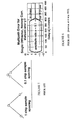
- FIGURE 1 is a prior art illustration of the multipath problem addressed by the present invention
- FIGURES 2-3 are prior art illustrations of the single reflector multipath problem
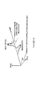
- FIGURE 4 illustrates the diffuse multipath problem
- FIGURES 5-6 address the prior art narrow correlator technique to mitigate multipath problems
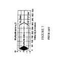
- FIGURE 7 illustrates multipath error correction by the prior art multipath estimating delay lock loop receivers
- FIGURE 8 illustrates the effect of narrow correlator techniques on P(Y)-code receivers
- FIGURES 9-19 illustrate a presently preferred technique for recognizing quadrature condition in most GPS receivers in accordance with an example aspect of the present invention
- FIGURE 20 illustrates a receiver embodiment in accordance with an example embodiment of the present invention
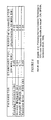
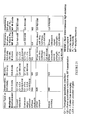
- FIGURE 21 is a table of example benefits of embodiments of the present QMFR system.
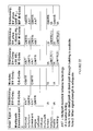
- FIGURE 22 is a table of recommended approaches for multipath mitigation in addition to narrow correlation.
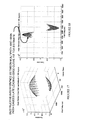
- FIGURE 23 illustrates QMFR experimental effectiveness in addressing the multipath problem.
- the TOA estimate is degraded by interference of delayed multipath signals with the correlation peak due to the undelayed main path signal, shown in Figure 9. This is particularly true for multipath signals that are delayed by less than 1.5 times the chip duration.
- Receivers other than the present invention such as the narrow correlator, MEDLL, and leading edge curve fitting embodiments, do not improve performance as well as the present invention. Even when the above mentioned curve fitting on the leading edge of the received signal is used as a correlation function, the influence of a close-in multipath component is still severely degrading as to the TOA estimates.
- the narrow correlator and MEDLL techniques although they significantly improve performance against multipath, still do not take advantage of the quadrature condition, as described below.
- to extend the narrow correlator technique to work for P(Y)-code and M-code would require a large bandwidth increase in order to achieve significantly improved multipath performance.
- the presently preferred embodiment of the present invention utilizes the QMFR technique and extends it to application of the GPS multipath problem.
- the QMFR technique reduces the influence of close-in multipath components by examining the complex correlation function of the received signal rather than just the magnitude of the correlation function.
- the QMFR concept utilizes the complex correlation function in which the main path and multipath components arrive with arbitrary phase angles in the complex correlation.
- the preferred embodiment uses curve fitting on the complex correlation signal to locate the correlation peaks due to the main (undelayed) path and the delayed multipath component, and then measures the phase angle between these peaks.
- the preferred embodiment of the present invention applies first and second QMFR principles.
- the first QMFR principle (Q1) supposes that the best TOA estimate on the main path can be obtained when the delayed multipath component is at a 90 degree angle to the main path, as shown in Figure 19. Recognizing this first principle, the present invention utilizes the understanding that the main path and multipath components arrive with arbitrary phase angles in the complex correlation and that certain phase angles have less interference by the multipath component on the main path's leading edge. The present inventors have found that the best angle is 90 degrees and thus the QMFR concept of the preferred embodiment waits for this 90 degree angle condition to occur and then measures the TOA.
- the preferred embodiment detects an instance when the 90 degree or "quadrature” condition occurs, and then does leading edge curve-fitting on the main path in the complex domain. This results in significantly higher TOA accuracy than leading edge curve fitting on the magnitude of the correlation function. Locating and utilizing the quadrature condition also gives improved performance over narrow correlator and MEDLL, which operate at arbitrary phase angles between the direct and multipaths. Also there is no increase in bandwidth necessary to use the quadrature condition for P(Y)-code or M-code, unlike what is required with narrow correlation.
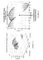
- Figures 11-18 are graphical representations of the advantages gained by the present invention.
- Figure 11 and 12 are, respectively, three-dimensional and two-dimensional displays of the correlation function with the multipath delayed by 1.2 chips (using C/A code).
- the angle between the main path and the multipath is 0 degrees.
- the constructive interference between the multipath and main path causes an early leading edge curve fit TOA estimate.
- Figures 13 and 14 are similar three-dimensional and two-dimensional graphs illustrating the correlation function when the angle between the main path and the multipath is 90 degrees. As shown particularly in Figure 14, the maximum amplitude of the main path occurs with no interference from the multipath at the angle of 90 degrees.
- Figures 15 and 16 are, respectively, three-dimensional and two-dimensional graphs where the angle between the main path and multipath is set at 120 degrees, rather than the 90 degrees shown in Figures 13 and 14. At 120 degrees, the main path amplitude is reduced, as particularly shown in Figure 16.
- Figures 17 and 18 are three-dimensional and two-dimensional graphs, respectively, where the angle between the main path and multipath is 180 degrees. As shown in Figure 18, destructive interference occurs between the multipath and main path causing a late leading edge curve fit TOA estimate.
- Figures 11 through 18 illustrate the optimal advantages gained when the multipath component is at 90 degrees to the main path.
- the phase angle between the main or multipath (delayed) signal is of course arbitrary, so only on occasion will this quadrature condition occur.
- the preferred embodiment of the present invention waits for the quadrature condition to arbitrarily occur and then does leading edge curve fitting on the main path in the complex domain based on the signals obtained at the general occurrence of the quadrature condition.
- the 90 degree angle between the main path and multipath gives the lowest TOA standard deviation.
- the quadrature condition can provide a TOA estimation brought to within a few dB of the Cramer-Rao bound.
- the present inyention can avoid TOA estimation degradations of 5-10 dB due to worst case interference between the main path and the multipath.
- the worst case interference occurred near zero degrees and 180 degrees, and the lowest TOA standard deviation occurred when the main path and the multipath were 90 degrees to each other.
- the preferred embodiment of the present invention in which the quadrature condition is awaited provides improved accuracy over the narrow correlator or MEDLL prior techniques, which operate at all arbitrary phase angles between the direct path and the multipath. Further, the presently preferred embodiment can employ even more rapid measurements than required for smoothing across phase angles for several cycles. Further, extension of improved accuracy of P(Y)-code or M-code receivers is also possible with the present invention, without demanding large increases in SV transmit bandwidth.
- the present invention relies upon a second QMFR principle (Q2) as well, namely if a signal is transmitted at a series of frequencies, and the spread of these frequencies is sufficient, a quadrature (or near-quadrature) condition can be forced to occur.
- Q2 Q2
- the quadrature condition is the optimum condition for obtaining the leading edge curve fitting on the main path in the complex domain
- the principle of Q2 seeks to force that advantageous condition to occur. This principle recognizes that the angle between the main path and the multiple path will differ at different frequencies, but if the signal is transmitted at a series of frequencies and the spread of those frequencies is sufficient, the quadrature condition (or near-quadrature condition) will be forced to occur.
- This principle is applied by having the transmitter frequency hop at a series of frequencies that span the required frequency spread. Then, a suitably-equipped receiver receives the GPS signal on all these frequencies, looks at the phase angle between the direct and multipaths, and chooses the hop frequency which comes closest to achieving the quadrature condition. A TOA measurement made on this frequency will have the best separation between the direct path and the multipath, and on average will have the lowest TOA error.
- the QMFR implementation is as follows:
- the resultant waveform code exceeds the spectral allocation for GPS.
- Spectral spillover for M-code with QMFR will be limited to a small region because of the spot beam.
- the spot beam is a special focused energy beam transmitted from a special antenna located on the satellite, as opposed to the standard earth coverage GPS signal.
- pulsed operation minimizes interference with the signal from the space vehicle and reduces the effect of any spillover into frequency allocations other than those allocated to global navigation satellite system (GNSS).
- GNSS global navigation satellite system
- FIG 20 illustrates an example embodiment of a receiver employing aspects of the present invention.
- the receiver receives base band GPS signals "RXI” and “RXQ” and inputs them respectively into the chip matched filters (CMFs), which input them to the Digital Matched Filters (DMF), for correlation with a replica of the digital transmission signal.
- the output of the DMF is the complex correlation function DMFI and DMFQ.
- the complex correlation function is provided to the curve fitting algorithm portion, which also receives the theoretically received pulse shape.
- the curve fitting algorithm outputs main and multi path signals to the "select quadrature condition" portion (TOA and angle) where the quadrature condition is detected and timed for obtaining the TOA estimate.
- the select quadrature condition portion applies the principles of QMFR to obtain the main path TOA, in accordance with the principles previously identified.
- the transmitter components include a standard GPS signal generator, RF frequency hopping device, which offsets the frequency of the transmitted GPS signal, and (for pseudolites only) a switching device to turn the transmitter rapidly on and off for pulsed operation.
- the receiver components include the RF frequency hopping device, which offsets the frequency of the received GPS signal in synchronization with the frequency hopped transmit signal. Also, for reception of pseudolites only, a switching device to turn the receiver rapidly on and off in synchronization with the pulse transmitter is required. Then, the correlator device is included in the receiver that generates the base band in-phase and quadrature components of the correlation between the received signal and a replica of the digital transmitted signal (in DMF, Figure 20). The curve fitting device then implements the algorithm to determine amplitude, delay, and phase angle of (i) the direct signal and (ii) the largest of the delayed (multipath) signals. This occurs in the curve fitting algorithm box of Figure 20. Finally, the receiver includes the selection device which decides which frequency hop comes closest to yielding the quadrature condition, and a leading edge curve fitting algorithm that performs the TOA estimation. This is included in Figure 20 in the select quadrature condition box.
- Figure 21 illustrates the benefits of the present invention in resolving different multipath environment problems.
- the multipath environments discussed in the background previously, including ground reflection, dominant single reflector, etc., are shown in the vertical left column.
- the user type and bode type are shown across the top of the table, including users that are stationary versus mobile, and using C/A-code, M-code, etc.
- the reference “Q1" refers to application of the first principle of the QMFR technique, namely the recognition of the quadrature condition having occurred for optimal curve fitting.
- Q2 refers to the second QMFR principle, namely that the quadrature condition can be forced via multi-frequency (MF) transmission.
- MF multi-frequency
- the table indicates in which instances and for which multipath problems, Q1 and Q2 are found to be faster than averaging, better at lower elevation angles, near instantaneous high accuracy measurements, or no benefit. As shown in the table, each of the various benefits, together with the Q1 and Q2 principles are illustrated.
- QMFR quadrature condition between direct and delayed path and offers a faster means to high-accuracy than smoothing multi-path effects.
- Q2 forces the quadrature condition to occur via multiple frequency transmission, and provides near instantaneous high-accuracy measurements under many multipath conditions.
- QMFR which combines Q1 and Q2, gives users significantly improved accuracy in many multipath environments, as illustrated in Figures 21 and 22. Further, QMFR, when transmitted via a UHF-band pseudolite, supports high-accuracy navigation in urban canyons and inside of buildings.
- strong local area GPS signals can be provided with multiple frequencies to force the quadrature condition.
- the UHF-band can be used for pseudolite signals to obtain better performance in urban environments. Both the urban and building environments are illustrated in Figures 21 and 22, as previously described.
- the present invention can find application in a wide variety of different applications.
- receivers which detect the quadrature condition between the direct path of a delayed path i.e., the multiple path
- the normal motion of the satellites or motion of the receiver that causes variation in the phase angle between the direct and delayed paths can now be exploited to locate a quadrature or near quadrature condition and then perform TOA estimation with high-accuracy.
- transmitters which force the quadrature condition to occur also have application in the preferred embodiment of the present invention.
- the following transmitters allow suitably equipped receivers to achieve high TOA measurement accuracy nearly instantaneously with multipath delay as close as 1 ⁇ 4 chip (chip duration varying according to the code):
- the present invention may find application in receivers which frequency hop along with the preceding transmitters, deciding which frequency hop comes closest to the quadrature condition, and then carrying out leading edge curve fitting to achieve high accuracy TOA estimation.
- receivers and transmitters described above are applicable for improved performance against multipath in all environments where GPS is used, including terrestrial, marine, airborne and space.
Landscapes
- Engineering & Computer Science (AREA)
- Radar, Positioning & Navigation (AREA)
- Remote Sensing (AREA)
- Computer Networks & Wireless Communication (AREA)
- Physics & Mathematics (AREA)
- General Physics & Mathematics (AREA)
- Position Fixing By Use Of Radio Waves (AREA)
- Noise Elimination (AREA)
Applications Claiming Priority (2)
| Application Number | Priority Date | Filing Date | Title |
|---|---|---|---|
| US30351101P | 2001-07-09 | 2001-07-09 | |
| US303511P | 2001-07-09 |
Publications (3)
| Publication Number | Publication Date |
|---|---|
| EP1275975A2 true EP1275975A2 (de) | 2003-01-15 |
| EP1275975A3 EP1275975A3 (de) | 2003-12-10 |
| EP1275975B1 EP1275975B1 (de) | 2006-06-07 |
Family
ID=23172448
Family Applications (1)
| Application Number | Title | Priority Date | Filing Date |
|---|---|---|---|
| EP02014984A Expired - Lifetime EP1275975B1 (de) | 2001-07-09 | 2002-07-09 | Quadratur mehrfrequenz Entfernungsmessung für GPS-Mehrwegeverringerung |
Country Status (2)
| Country | Link |
|---|---|
| EP (1) | EP1275975B1 (de) |
| DE (1) | DE60212005T2 (de) |
Cited By (2)
| Publication number | Priority date | Publication date | Assignee | Title |
|---|---|---|---|---|
| GB2383709A (en) * | 2001-09-05 | 2003-07-02 | Thales Res Ltd | Position fixing; spread spectrum modulation of frequency hopped carrier |
| CN103292782A (zh) * | 2013-05-21 | 2013-09-11 | 西安电子科技大学 | 基于遗传算法及粒子滤波的红外目标被动测距方法 |
Families Citing this family (11)
| Publication number | Priority date | Publication date | Assignee | Title |
|---|---|---|---|---|
| US7612716B2 (en) | 1999-03-05 | 2009-11-03 | Era Systems Corporation | Correlation of flight track data with other data sources |
| US8446321B2 (en) | 1999-03-05 | 2013-05-21 | Omnipol A.S. | Deployable intelligence and tracking system for homeland security and search and rescue |
| US7739167B2 (en) | 1999-03-05 | 2010-06-15 | Era Systems Corporation | Automated management of airport revenues |
| US7782256B2 (en) | 1999-03-05 | 2010-08-24 | Era Systems Corporation | Enhanced passive coherent location techniques to track and identify UAVs, UCAVs, MAVs, and other objects |
| US7908077B2 (en) | 2003-06-10 | 2011-03-15 | Itt Manufacturing Enterprises, Inc. | Land use compatibility planning software |
| US8203486B1 (en) | 1999-03-05 | 2012-06-19 | Omnipol A.S. | Transmitter independent techniques to extend the performance of passive coherent location |
| US7889133B2 (en) | 1999-03-05 | 2011-02-15 | Itt Manufacturing Enterprises, Inc. | Multilateration enhancements for noise and operations management |
| US7667647B2 (en) | 1999-03-05 | 2010-02-23 | Era Systems Corporation | Extension of aircraft tracking and positive identification from movement areas into non-movement areas |
| US7777675B2 (en) | 1999-03-05 | 2010-08-17 | Era Systems Corporation | Deployable passive broadband aircraft tracking |
| US7570214B2 (en) | 1999-03-05 | 2009-08-04 | Era Systems, Inc. | Method and apparatus for ADS-B validation, active and passive multilateration, and elliptical surviellance |
| US7965227B2 (en) | 2006-05-08 | 2011-06-21 | Era Systems, Inc. | Aircraft tracking using low cost tagging as a discriminator |
Family Cites Families (1)
| Publication number | Priority date | Publication date | Assignee | Title |
|---|---|---|---|---|
| US6453168B1 (en) * | 1999-08-02 | 2002-09-17 | Itt Manufacturing Enterprises, Inc | Method and apparatus for determining the position of a mobile communication device using low accuracy clocks |
-
2002
- 2002-07-09 DE DE60212005T patent/DE60212005T2/de not_active Expired - Lifetime
- 2002-07-09 EP EP02014984A patent/EP1275975B1/de not_active Expired - Lifetime
Cited By (3)
| Publication number | Priority date | Publication date | Assignee | Title |
|---|---|---|---|---|
| GB2383709A (en) * | 2001-09-05 | 2003-07-02 | Thales Res Ltd | Position fixing; spread spectrum modulation of frequency hopped carrier |
| GB2383709B (en) * | 2001-09-05 | 2005-03-30 | Thales Res Ltd | Position fixing system |
| CN103292782A (zh) * | 2013-05-21 | 2013-09-11 | 西安电子科技大学 | 基于遗传算法及粒子滤波的红外目标被动测距方法 |
Also Published As
| Publication number | Publication date |
|---|---|
| DE60212005D1 (de) | 2006-07-20 |
| DE60212005T2 (de) | 2006-10-05 |
| EP1275975A3 (de) | 2003-12-10 |
| EP1275975B1 (de) | 2006-06-07 |
Similar Documents
| Publication | Publication Date | Title |
|---|---|---|
| US7154937B2 (en) | Quadrature multi-frequency ranging (QMFR) applied to GPS multipath mitigation | |
| Chen et al. | Comparative studies of GPS multipath mitigation methods performance | |
| Psiaki et al. | GPS spoofing detection via dual-receiver correlation of military signals | |
| CN102037658B (zh) | 码空间搜索中的多相关处理 | |
| EP1275975B1 (de) | Quadratur mehrfrequenz Entfernungsmessung für GPS-Mehrwegeverringerung | |
| US8520717B2 (en) | GNSS receiver with cross-correlation rejection | |
| US8947298B2 (en) | GNSS receiver and positioning method | |
| EP2066040A1 (de) | GNSS-Empfänger mit Mehrwegkompensation | |
| US20180180742A1 (en) | Multipath mitigation in a gnss radio receiver | |
| CN117288186A (zh) | 卫星扰动环境下的gnss/sins组合导航信号检测与抗干扰方法 | |
| Bhuiyan et al. | A slope-based multipath estimation technique for mitigating short-delay multipath in GNSS receivers | |
| Balaei et al. | Cross correlation impacts and observations in GNSS receivers | |
| US9236903B2 (en) | Multi-path detection | |
| KR101576463B1 (ko) | 항법신호 추적장치 및 그것의 제어방법 | |
| JP5423530B2 (ja) | Gnss受信装置及び測位方法 | |
| EP3311199A1 (de) | Verfahren zur verarbeitung von offset-trägermodulierten entfernungsmesssignalen | |
| Mubarak | Performance comparison of multipath detection using early late phase in BPSK and BOC modulated signals | |
| US11757487B2 (en) | Systems and methods for long range, high-capacity multipoint distance and velocity measurement | |
| Draganov et al. | Inverse beamforming for navigating in multipath environments | |
| JP2010276495A (ja) | 受信機 | |
| Bouhanna et al. | Inter-Satellite Range Estimation Using Discovery & Resolution Modes for Space Traffic Management | |
| Liu et al. | Tracking performance of the coherent and noncoherent discriminators in strong multipath | |
| Schmid et al. | Channel estimation technique for positioning accuracy improvement in multipath propagation scenarios | |
| Lim et al. | A Novel Short Delay Multipath Mitigation Algorithm in Urban GNSS Navigation Applications | |
| Adeel et al. | Sensitivity level enhancement in vehicular DGPS receivers to provide exact location tracking on sub-lane of a highway |
Legal Events
| Date | Code | Title | Description |
|---|---|---|---|
| PUAI | Public reference made under article 153(3) epc to a published international application that has entered the european phase |
Free format text: ORIGINAL CODE: 0009012 |
|
| AK | Designated contracting states |
Kind code of ref document: A2 Designated state(s): AT BE BG CH CY CZ DE DK EE ES FI FR GB GR IE IT LI LU MC NL PT SE SK TR |
|
| AX | Request for extension of the european patent |
Free format text: AL;LT;LV;MK;RO;SI |
|
| PUAL | Search report despatched |
Free format text: ORIGINAL CODE: 0009013 |
|
| AK | Designated contracting states |
Kind code of ref document: A3 Designated state(s): AT BE BG CH CY CZ DE DK EE ES FI FR GB GR IE IT LI LU MC NL PT SE SK TR |
|
| AX | Request for extension of the european patent |
Extension state: AL LT LV MK RO SI |
|
| 17P | Request for examination filed |
Effective date: 20040210 |
|
| 17Q | First examination report despatched |
Effective date: 20040331 |
|
| AKX | Designation fees paid |
Designated state(s): DE FR GB IT |
|
| GRAP | Despatch of communication of intention to grant a patent |
Free format text: ORIGINAL CODE: EPIDOSNIGR1 |
|
| RTI1 | Title (correction) |
Free format text: QUADRATURE MULTI-FREQUENCY RANGING (QMFR) APPLIED TO GPS MULTIPATH MITIGATION |
|
| GRAS | Grant fee paid |
Free format text: ORIGINAL CODE: EPIDOSNIGR3 |
|
| GRAA | (expected) grant |
Free format text: ORIGINAL CODE: 0009210 |
|
| AK | Designated contracting states |
Kind code of ref document: B1 Designated state(s): DE FR GB IT |
|
| REG | Reference to a national code |
Ref country code: GB Ref legal event code: FG4D |
|
| REF | Corresponds to: |
Ref document number: 60212005 Country of ref document: DE Date of ref document: 20060720 Kind code of ref document: P |
|
| ET | Fr: translation filed | ||
| PLBE | No opposition filed within time limit |
Free format text: ORIGINAL CODE: 0009261 |
|
| STAA | Information on the status of an ep patent application or granted ep patent |
Free format text: STATUS: NO OPPOSITION FILED WITHIN TIME LIMIT |
|
| 26N | No opposition filed |
Effective date: 20070308 |
|
| PGFP | Annual fee paid to national office [announced via postgrant information from national office to epo] |
Ref country code: DE Payment date: 20110727 Year of fee payment: 10 |
|
| REG | Reference to a national code |
Ref country code: DE Ref legal event code: R082 Ref document number: 60212005 Country of ref document: DE Representative=s name: SCHWABE SANDMAIR MARX, DE |
|
| REG | Reference to a national code |
Ref country code: DE Ref legal event code: R081 Ref document number: 60212005 Country of ref document: DE Owner name: EXELIS INC. (N. D. GES. D. STAATES INDIANA), US Free format text: FORMER OWNER: ITT MANUFACTURING ENTERPRISES, INC., WILMINGTON, US Effective date: 20121009 Ref country code: DE Ref legal event code: R082 Ref document number: 60212005 Country of ref document: DE Representative=s name: SCHWABE SANDMAIR MARX, DE Effective date: 20121009 |
|
| REG | Reference to a national code |
Ref country code: GB Ref legal event code: 732E Free format text: REGISTERED BETWEEN 20130110 AND 20130116 |
|
| REG | Reference to a national code |
Ref country code: FR Ref legal event code: TP Owner name: EXELIS INC., US Effective date: 20130131 |
|
| PG25 | Lapsed in a contracting state [announced via postgrant information from national office to epo] |
Ref country code: DE Free format text: LAPSE BECAUSE OF NON-PAYMENT OF DUE FEES Effective date: 20130201 |
|
| REG | Reference to a national code |
Ref country code: FR Ref legal event code: CD Owner name: EXELIS INC., US Effective date: 20130402 |
|
| REG | Reference to a national code |
Ref country code: DE Ref legal event code: R119 Ref document number: 60212005 Country of ref document: DE Effective date: 20130201 |
|
| REG | Reference to a national code |
Ref country code: FR Ref legal event code: PLFP Year of fee payment: 15 |
|
| REG | Reference to a national code |
Ref country code: FR Ref legal event code: PLFP Year of fee payment: 16 |
|
| REG | Reference to a national code |
Ref country code: FR Ref legal event code: PLFP Year of fee payment: 17 |
|
| REG | Reference to a national code |
Ref country code: GB Ref legal event code: 732E Free format text: REGISTERED BETWEEN 20190207 AND 20190213 |
|
| PGFP | Annual fee paid to national office [announced via postgrant information from national office to epo] |
Ref country code: FR Payment date: 20190725 Year of fee payment: 18 Ref country code: IT Payment date: 20190726 Year of fee payment: 18 |
|
| PGFP | Annual fee paid to national office [announced via postgrant information from national office to epo] |
Ref country code: GB Payment date: 20190729 Year of fee payment: 18 |
|
| GBPC | Gb: european patent ceased through non-payment of renewal fee |
Effective date: 20200709 |
|
| PG25 | Lapsed in a contracting state [announced via postgrant information from national office to epo] |
Ref country code: GB Free format text: LAPSE BECAUSE OF NON-PAYMENT OF DUE FEES Effective date: 20200709 Ref country code: FR Free format text: LAPSE BECAUSE OF NON-PAYMENT OF DUE FEES Effective date: 20200731 |
|
| PG25 | Lapsed in a contracting state [announced via postgrant information from national office to epo] |
Ref country code: IT Free format text: LAPSE BECAUSE OF NON-PAYMENT OF DUE FEES Effective date: 20200709 |