EP1275978A2 - RPC-Schaltung für Dauerstrichradar - Google Patents
RPC-Schaltung für Dauerstrichradar Download PDFInfo
- Publication number
- EP1275978A2 EP1275978A2 EP02010394A EP02010394A EP1275978A2 EP 1275978 A2 EP1275978 A2 EP 1275978A2 EP 02010394 A EP02010394 A EP 02010394A EP 02010394 A EP02010394 A EP 02010394A EP 1275978 A2 EP1275978 A2 EP 1275978A2
- Authority
- EP
- European Patent Office
- Prior art keywords
- line
- circulator
- line branch
- continuous wave
- directional coupler
- Prior art date
- Legal status (The legal status is an assumption and is not a legal conclusion. Google has not performed a legal analysis and makes no representation as to the accuracy of the status listed.)
- Granted
Links
Images

Classifications
-
- G—PHYSICS
- G01—MEASURING; TESTING
- G01S—RADIO DIRECTION-FINDING; RADIO NAVIGATION; DETERMINING DISTANCE OR VELOCITY BY USE OF RADIO WAVES; LOCATING OR PRESENCE-DETECTING BY USE OF THE REFLECTION OR RERADIATION OF RADIO WAVES; ANALOGOUS ARRANGEMENTS USING OTHER WAVES
- G01S13/00—Systems using the reflection or reradiation of radio waves, e.g. radar systems; Analogous systems using reflection or reradiation of waves whose nature or wavelength is irrelevant or unspecified
- G01S13/02—Systems using reflection of radio waves, e.g. primary radar systems; Analogous systems
- G01S13/06—Systems determining position data of a target
- G01S13/08—Systems for measuring distance only
- G01S13/32—Systems for measuring distance only using transmission of continuous waves, whether amplitude-, frequency-, or phase-modulated, or unmodulated
- G01S13/34—Systems for measuring distance only using transmission of continuous waves, whether amplitude-, frequency-, or phase-modulated, or unmodulated using transmission of continuous, frequency-modulated waves while heterodyning the received signal, or a signal derived therefrom, with a locally-generated signal related to the contemporaneously transmitted signal
-
- G—PHYSICS
- G01—MEASURING; TESTING
- G01S—RADIO DIRECTION-FINDING; RADIO NAVIGATION; DETERMINING DISTANCE OR VELOCITY BY USE OF RADIO WAVES; LOCATING OR PRESENCE-DETECTING BY USE OF THE REFLECTION OR RERADIATION OF RADIO WAVES; ANALOGOUS ARRANGEMENTS USING OTHER WAVES
- G01S7/00—Details of systems according to groups G01S13/00, G01S15/00, G01S17/00
- G01S7/02—Details of systems according to groups G01S13/00, G01S15/00, G01S17/00 of systems according to group G01S13/00
- G01S7/03—Details of HF subsystems specially adapted therefor, e.g. common to transmitter and receiver
- G01S7/038—Feedthrough nulling circuits
-
- G—PHYSICS
- G01—MEASURING; TESTING
- G01S—RADIO DIRECTION-FINDING; RADIO NAVIGATION; DETERMINING DISTANCE OR VELOCITY BY USE OF RADIO WAVES; LOCATING OR PRESENCE-DETECTING BY USE OF THE REFLECTION OR RERADIATION OF RADIO WAVES; ANALOGOUS ARRANGEMENTS USING OTHER WAVES
- G01S7/00—Details of systems according to groups G01S13/00, G01S15/00, G01S17/00
- G01S7/02—Details of systems according to groups G01S13/00, G01S15/00, G01S17/00 of systems according to group G01S13/00
- G01S7/35—Details of non-pulse systems
- G01S7/352—Receivers
-
- G—PHYSICS
- G01—MEASURING; TESTING
- G01S—RADIO DIRECTION-FINDING; RADIO NAVIGATION; DETERMINING DISTANCE OR VELOCITY BY USE OF RADIO WAVES; LOCATING OR PRESENCE-DETECTING BY USE OF THE REFLECTION OR RERADIATION OF RADIO WAVES; ANALOGOUS ARRANGEMENTS USING OTHER WAVES
- G01S7/00—Details of systems according to groups G01S13/00, G01S15/00, G01S17/00
- G01S7/02—Details of systems according to groups G01S13/00, G01S15/00, G01S17/00 of systems according to group G01S13/00
- G01S7/35—Details of non-pulse systems
- G01S7/352—Receivers
- G01S7/358—Receivers using I/Q processing
Definitions
- the invention relates to a continuous wave radar according to the preamble of claim 1.
- Continuous wave radars include a transmitter circuit for generating radar transmit signals, a transmitting / receiving antenna coupled to the transmitter circuit via a circulator and one via the circulator with the transmit / receive antenna Coupled receiver circuit for processing on the transmit / receive antenna received radar echo signals of a target object.
- the circulator serves to forward the transmission signals generated by the transmitter circuit to the transmitting / receiving antenna and for deriving the from the transmitting / receiving antenna received echo signals of the target object to the input the receiver circuit.
- An RPC circuit is designed to suppress out of the Transmitter circuit and / or by reflection from the transmitting / receiving antenna directly parts of the transmission signals derived in the receiver circuit in response a control signal derived from the receiver circuit is provided.
- the RPC circuit contains one in the signal path between the circulator and the transmit / receive antenna switched reflection modulator circuit for generation one of the directly derived parts of the transmission signal compensating correction signal.
- the compensation or correction signal was provided to gain via a decoupling at the transmitter output, via a And finally control quadrature modulator circuit in amplitude and phase to feed into the signal path leading to the receiver circuit via a directional coupler.
- This previous concept has the advantage of largely separating the actual radar circuit and the RPC circuit as an additional component however expensive in terms of the number of components and their complexity, in particular the quadrature modulator circuit.
- a continuous wave radar with a common transmitting and receiving antenna offers the possibility of the compensation or correction signal through a controlled reflection point in the antenna feed line and thus a reflection modulator Circuit to form.
- Such a concept was already developed by John D. Harmer, William S. O'Hare, "Some Advances in CW Radar Techniques," Conference Proceedings of Nat. Conv. on Military Electronics, 1961, pp. 311-323.
- the object of the invention is a continuous wave radar of the type described to create that can be manufactured with components that can be integrated in a simple manner.
- the invention provides a continuous wave radar with a transmitter circuit for generation of radar signals, one via a circulator with the transmitter circuit coupled transmit / receive antenna and one via the circulator with the transmit / receive antenna coupled receiver circuit for processing at the Transmit / receive antenna received radar echo signals of a target object.
- the circulator is used to forward those generated by the transmitter circuit Transmit signals to the transmit / receive antenna and to derive the from Transmit / receive antenna received echo signals of the target object to the input the receiver circuit.
- an RPC circuit is provided which one in the Signal path switched between the circulator and the transmit / receive antenna Reflection modulator circuit for generating the directly derived parts contains the correction signal compensating the transmission signal.
- the reflection modulator circuit be a directional coupler arrangement to decouple part of the signal path between the circulator and the Transmitting / receiving antenna passing signal and one to the directional coupler arrangement connected controllable line termination arrangement for adjustment of reflection and / or absorption of the decoupled signal in the sense of a Generation of the correction signal in response to that from the receiver circuit derived control signal contains.
- a major advantage of the type of circuit according to the invention is that the reflection modulator circuit in an integrable manner in different line techniques can be produced. Another advantage is that a quadrature (90 ° shift of I and Q signals) over a wide frequency range.
- the Directional coupler arrangement a first directional coupler and one over this with the Signal path between the circulator and the transmitting / receiving antenna coupled first Line branch for decoupling an in-phase component from this signal path and a second directional coupler and one with the signal path between them Circulator and transmitting / receiving antenna coupled second line branch for decoupling contains a quadrature component from this signal path, and that at at one end of the first line branch a first controllable line termination for Adjustment of reflection and / or absorption of the decoupled in-phase component and at one end of the second line branch a second controllable line termination to adjust the reflection and / or absorption of the decoupled Quadrature component is provided.
- the decoupled waves can by of the controllable line terminations depending on their tax status with positive or negative phase are reflected or completely absorbed.
- the reflected waves run via the directional coupler into the signal path between the circulator and the transmitting / receiving antenna back to where they occur reduced by the coupling factor and run as reflected waves backwards to the circulator and from there to the receiver and can compensate for an unwanted coupling signal.
- first absorber At the other end of the first line branch a first absorber is provided and that at the other end of the a second absorber is provided corresponding to the second line branch.
- the directional coupler arrangement a first directional coupler for dividing a connected to the circulator first part of the signal path between the circulator and Transmitting / receiving antenna in a first line branch and a second line branch, a second and third directional coupler for coupling the first and second Line branch with a third and fourth line branch, as well as one fourth directional coupler to combine the third and fourth line branch a second part of the signal path connected to the transmitting / receiving antenna contains between circulator and transmitting / receiving antenna, and that at one Controllable line terminations for setting reflection at the end of the line branches and / or absorption of in-phase and quadrature components from the Signal path decoupled signal are provided.
- This embodiment does the property of directional couplers to use that the decoupled shaft and the shaft on the main line are 90 ° out of phase, which is for the purpose of Quadrature and can be used to cancel signal components.
- a controllable line termination is preferably at one end of the first line branch provided and the other end of the first line branch is with connected to the circulator.
- each end of the second and third line branch controllable line termination is provided and at the other end of the second and an absorber is provided in each third line branch.
- controllable line terminations are preferably each in pairs assigned at one end of the first and third line branch and at one end of the second and fourth line branch provided.
- controllable line terminations by PIN diodes be formed by FET circuits or by varactor diodes.
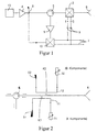
- reference numeral 13 denotes one Transmitter of a frequency modulated continuous wave radar.
- the transmitter 13 is an amplifier output stage 4 downstream.
- the formed from the transmitter and the final stage 4 Transmitter circuit 13, 4 is used to generate radar transmission signals, which one Transmit / receive antenna 6 can be fed, which via a circulator 5 with the Transmitter circuit 13, 4 is coupled.
- the receiver circuit 9, 10 includes a low noise RF receiver amplifier 9 and one Receiver mixer 10.
- the receiver circuit 9, 10 is used to process from the transmit / receive antenna 6 received and via the circulator 5 in the Receiver amplifier 9 fed radar echo signals of a target object.
- the circulator 5 ensures on the one hand the forwarding of those generated by the transmitter circuit 13, 4 Transmit signals to the transmit / receive antenna 6 and on the other hand the derivative the echo signals of the target object received by the transmitting / receiving antenna 6 to the input of the receiver circuit 9, 10.
- the Receiver mixer 10 is also supplied with part of the transmission signal which Via a directional coupler 8 from the signal path between the transmitter circuit 4, 13 and the circulator 5 is coupled out.
- the reflection modulator 2 and the control amplifier 3 formed RPC circuit 2, 3 generated in response to the control signal derived from the receiver circuit 9, 10 is a correction signal which which from the transmitter circuit 13, 4 by coupling in the circulator 5 directly in the receiver circuit 9, 10 or by reflection from the transmitting / receiving antenna 6 without radiation by the same directly into the receiver circuit 9, 10 derived parts of the transmission signal compensated.
- FIGS. 2 and 3 show reflection modulator circuits 2 according to two exemplary embodiments presented the invention.
- the reflection modulator circuits 2 are in the signal path between the circulator 5 and the transmit / receive antenna 6 of the continuous wave radar switched.
- the reflection modulator circuit contains 2 shows a directional coupler arrangement, namely the directional couplers K1, K2 in the embodiment of Figure 2 and the directional coupler K1 ', K2', K3 ', K4' the embodiment of Figure 3.
- This directional coupler is used for decoupling part of the signal path between the circulator 5 and the transmitting / receiving antenna 6 continuous signal.
- the directional coupler arrangement contains K1, K2 in detail a first directional coupler K1 and one with this the signal path between circulator 5 and the transmitting / receiving antenna 6 coupled first line branch 11.
- the first directional coupler K1 is used together with the first line branch 11 for decoupling an in-phase component I from the Signal path between circulator 5 and transmit / receive antenna 6.
- the second directional coupler K2 and the second Line branch 12 are used to couple a quadrature component Q from the Signal path between the circulator 5 and the transmit / receive antenna 6.
- first controllable line termination 31 At one At the end of the first line branch 11 is a first controllable line termination 31 provided and at one end of the second line branch 12 is a second controllable Line termination 32 is provided.
- the two controllable line terminations 31, 32 are used to adjust the reflection and / or absorption of the decoupled In-phase component I or the decoupled quadrature phase component Q.
- a respective first absorber 51 or second absorber 52 is provided at the other end of the first line branch 11 or of the second line branch 12 .
- the transmission signal running from the circulator 5 to the transmission / reception antenna 6 or that in the opposite direction from the transmitting / receiving antenna 6 Signal reflected without radiation becomes part according to the coupling factor through the directional coupler K1, K2 onto the first line branch 11 (in-phase component I) or on the second line branch 12 (quadrature phase component Q) decoupled.
- controllable line terminations 31 and 32 are the decoupled Waves depending on the tax status of the controllable line terminations 31, 32 reflected with positive or negative phase or completely or partially absorbed, depending on the ratio of characteristic impedance and resistance of the controllable Line termination 31 or 32.
- the reflected waves run into the directional coupler K1, K2 back where they decreased by the coupling factor again on the signal path occur between circulator 5 and transmitting / receiving antenna 6 and as reflected Waves backwards to the circulator 5 and from there to the receiver circuit 9, 10 run and can compensate for the unwanted coupling signal.
- controllable line terminations 31, 32 as they are from the state of the Technology for a wide variety of line types, such as waveguides or microstrip lines are known, for example using PIN diodes, as in Figure 4a), or for example using an FET circuit, as in FIG 4b) can be realized.
- PIN diodes as in Figure 4a
- FET circuit as in FIG 4b
- the directional coupler arrangement contains a first one Directional coupler K1 'for dividing a first connected to the circulator 5 Part of the signal path between circulator 5 and transmitting / receiving antenna 6 in one first line branch 21 and a second line branch 22.
- a second and a third directional coupler K2 ', K3' is on the first line branch 21 and on the second Line branch 22 is provided and couples each with a third line branch 23 or a fourth line branch 24.
- a fourth line which is also provided Directional coupler K4 ' is arranged so that it the third line branch 23 and fourth line branch 24 to one connected to the transmission / reception antenna 6 summarizes the second part of the signal path between circulator 5 and antenna 6.
- each line branch 21, 22, 23, 24 are controllable line terminations 41, 42, 43, 44 are provided, which are used to adjust reflection and / or Absorption of in-phase and quadrature phase components I, Q des from the Signal path coupled signal serve.
- a controllable line termination 41 is provided, the other end of the first line branch 21 is connected to the circulator 5.
- a controllable line termination 42, 43 is provided in each case and at the other end of the second and third line branches 22, 23 respectively an absorber 62, 63 is provided.
- the controllable line terminations 41, 42, 43, 44 are each assigned in pairs to one another at one end of the first and third line branches 21, 23 and at one end of the second and fourth line branch 22, 24 is provided.
- the function of the directional coupler arrangement shown in FIG. 3 takes on the property of directional couplers to use that the decoupled shaft and the shaft are 90 ° out of phase on the main line. For couplers with a -3 dB coupling factor this can result in a symmetrical arrangement of extinction of Signal components are used.
- the circuit shown in Figure 3 that Transmitting signal arriving from the circulator 5 first in the coupler K1 'to the first one Line branch 21 and the second line branch 22 divided. Everybody will Partial signal via the second directional coupler K2 'or the third directional coupler K3' given the third or fourth line branch 23 or 24.
- the respective partial waves are shifted by 45 °.
- the two partial waves are summed up again and led to the exit gate of the directional coupler arrangement, which with the transmitting / receiving antenna 6 is connected.
- the operation of the circuit is essentially depending on the state of the four controllable line terminations 41, 42, 43, 44. If the degrees are the same in pairs and the amount of reflection factor 1, the waves incident on the couplers from K1 'become complete passed on to K4 'and no reflected waves occur.
- paired line terminations 41, 42 and 43, 44 are set differently Parts of the signal are reflected and there is a returning partial wave, which over the directional coupler K1 'to the circulator 5 and via this to the receiving circuit 9, 10 is returned, the two in the first and second line branches 21, 22nd reflected partial signals are shifted by 90 ° to each other (I and Q signals).
- controllable line terminations 41, 42, 43, 44 can be carried out using those already described PIN diode or FET circuits according to Figure 4a) or b) realized become.
- Varactor diode circuits can also be used.
- Diode structures with a variety of discrete varactor or PIN diodes or with distributed integrated ones Diode structures can be used, or lines with electrically controllable dielectric material (ferroelectrics) up to electro-mechanically controlled lines and line elements (microsystem technology). Elements of this kind are on known to the state of the art.
Landscapes
- Engineering & Computer Science (AREA)
- Radar, Positioning & Navigation (AREA)
- Remote Sensing (AREA)
- Computer Networks & Wireless Communication (AREA)
- Physics & Mathematics (AREA)
- General Physics & Mathematics (AREA)
- Radar Systems Or Details Thereof (AREA)
- Transceivers (AREA)
Abstract
Description
- Figur 1
- ein Blockschaltbild einer Ausführungsform eines Dauerstrichradars zur Erläuterung der Grundzüge der Erfindung;
- Figur 2
- ein Schaltbild, welches eine Reflexions-Modulator- Schaltung gemäß einem Ausführungsbeispiel der Erfindung zeigt;
- Figur 3
- ein Schaltbild, welches eine Reflexions-Modulator- Schaltung gemäß einem anderen Ausführungsbeispiel der Erfindung zeigt; und
- Figur 4a) und b)
- Schaltbilder von steuerbaren Leitungsabschlüssen, wie sie in der erfindungsgemäßen Reflexions- Modulator-Schaltung Anwendung finden können.
- 2, 3
- RPC-Schaltung
- 2
- Modulator
- 3
- Regelverstärker
- 4
- Endstufe
- 5
- Zirkulator
- 6
- Sende/Empfangsantenne
- 7
- ZF-Signale
- 8
- erster Richtkoppler
- 9
- Empfängerverstärker
- 10
- Empfängermischer
- K1,K2
- Richtkoppler
- K1',K2',K3',K4'
- Richtkoppler
- 11, 12
- Leitungszweig
- 21, 22, 23, 24
- Leitungszweig
- 31, 32
- steuerbarer Leitungsabschluß
- 41, 42, 43, 44
- steuerbarer Leitungsabschluß
- 51, 52
- Absorber
- 62, 63
- Absorber
Claims (14)
- Dauerstrichradar mit einer Senderschaltung (4, 13) zur Erzeugung von Radarsendesignalen, einer über einen Zirkulator (5) mit der Senderschaltung (4, 13) gekoppelten Sende/Empfangsantenne (6) und einer über den Zirkulator (5) mit der Sende/Empfangsantenne (6) gekoppelten Empfängerschaltung (9, 10) zur Verarbeitung von an der Sende/Empfangsantenne (6) empfangenen Radarechosignalen eines Zielobjekts, wobei der Zirkulator (5) zur Weiterleitung der von der Senderschaltung (4, 13) erzeugten Sendesignale an die Sende/Empfangsantenne (6) und zur Ableitung der von der Sende/Empfangsantenne (6) empfangenen Echosignalen des Zielobjekts an den Eingang der Empfängerschaltung (9, 10) dient, und mit einer RPC-Schaltung (2, 3) zur Unterdrückung von aus der Senderschaltung (4, 13) und/oder durch Reflexion von der Sende/Empfangsantenne (6) direkt in die Empfängerschaltung (9, 10) abgeleiteten Teilen der Sendesignale in Ansprache auf ein von der Empfängerschaltung (9, 10) abgeleitetes Steuersignal, die eine in den Signalweg zwischen dem Zirkulator (5) und der Sende/Empfangsantenne (6) geschaltete Reflexions-Modulator-Schaltung (2) zur Erzeugung eines die direkt abgeleiteten Teile des Sendesignals kompensierenden Korrektursignals enthält, dadurch gekennzeichnet, daß die Reflexions-Modulator-Schaltung (2) eine Richtkoppleranordnung (K1, K2; K1', K2', K3', K4') zur Auskopplung eines Teils des den Signalweg zwischen den Zirkulator (5) und der Sende/Empfangsantenne (6) durchlaufenden Signals und eine an die Richtkoppleranordnung (K1, K2; K1', K2', K3', K4') angeschlossene steuerbare Leitungsabschlußanordnung (31, 32; 41, 42, 43, 44) zur Einstellung von Reflexion und/oder Absorption des ausgekoppelten Signals im Sinne der Erzeugung des Korrektursignals in Ansprache auf das von der Empfängerschaltung (9, 10) abgeleitete Steuersignal enthält.
- Dauerstrichradar nach Anspruch 1, dadurch gekennzeichnet, daß die Richtkoppleranordnung (K1, K2) einen ersten Richtkoppler (K1) und einen über diesen mit dem Signalweg zwischen Zirkulator (5) und Sende/Empfangsantenne (6) gekoppelten ersten Leitungszweig (11) zur Auskopplung einer Inphase-Komponente (I) aus diesem Signalweg und einen zweiten Richtkoppler (K2) und einen über diesen mit dem Signalweg zwischen Zirkulator (5) und Sende/Empfangsantenne (6) gekoppelten zweiten Leitungszweig (12) zur Auskopplung einer Quadratur-Komponente (Q) aus diesem Signalweg enthält, und daß an einem Ende des ersten Leitungszweigs (11) ein erster steuerbarer Leitungsabschluß (31) zur Einstellung von Reflexion und/oder Absorption der ausgekoppelten Inphase-Komponente (I) und an einem Ende des zweiten Leitungszweigs (12) ein zweiter steuerbarer Leitungsabschluß (32) zur Einstellung der Reflexion und/oder Absorption der ausgekoppelten Quadratur-Komponente (Q) vorgesehen ist.
- Dauerstrichradar nach Anspruch 2, dadurch gekennzeichnet, daß an dem anderen Ende des ersten Leitungszweigs (11) ein erster Absorber (51) vorgesehen ist, und daß an dem anderen Ende des zweiten Leitungszweigs (12) ein zweiter Absorber (52) vorgesehen ist.
- Dauerstrichradar nach Anspruch 1, dadurch gekennzeichnet, daß die Richtkoppleranordnung (K1', K2', K3', K4') einen ersten Richtkoppler (K1') zur Aufteilung eines mit dem Zirkulator (5) verbundenen ersten Teils des Signalwegs zwischen Zirkulator (5) und Sende/Empfangsantenne (6) in einen ersten Leitungszweig (21) und in einen zweiten Leitungszweig (22), einen zweiten und dritten Richtkoppler (K2', K3') zur Kopplung des ersten und zweiten Leitungszweigs (21, 22) jeweils mit einem dritten und vierten Leitungszweig (23, 24), sowie einen vierten Richtkoppler (K4') zum Zusammenfassen des dritten und vierten Leitungszweigs (23, 24) zu einem mit der Sende/Empfangsantenne (6) verbundenen zweiten Teil des Signalwegs zwischen Zirkulator (5) und Sende/Empfangsantenne (6) enthält, und daß an jeweils einem Ende der Leitungszweige (21, 22, 23, 24) steuerbare Leitungsabschlüsse (41, 42, 43, 44) zur Einstellung von Reflexion und/oder Absorption von Inphase- und Quadratur- Komponenten (I, Q) des aus dem Signalweg ausgekoppelten Signals vorgesehen sind.
- Dauerstrichradar nach Anspruch 4, dadurch gekennzeichnet, daß an einem Ende des ersten Leitungszweigs (21) ein steuerbarer Leitungsabschluß (41) vorgesehen und das andere Ende des ersten Leitungszweigs (21) mit dem Zirkulator (5) verbunden ist.
- Dauerstrichradar nach Anspruch 4 oder 5, dadurch gekennzeichnet, daß an einem Ende des vierten Leitungszweigs (24) ein steuerbarer Leitungsabschluß (44) vorgesehen und das andere Ende des vierten Leitungszweigs (24) mit der Sende/ Empfangsantenne (6) verbunden ist.
- Dauerstrichradar nach Anspruch 4, 5 oder 6, dadurch gekennzeichnet, daß an einem Ende des zweiten und dritten Leitungszweigs (22, 23) jeweils ein steuerbarer Leitungsabschluß (42, 43) vorgesehen und am anderen Ende des zweiten und dritten Leitungszweigs (22, 23) jeweils ein Absorber (62, 63) vorgesehen ist.
- Dauerstrichradar nach einem der Ansprüche 4 bis 7, dadurch gekennzeichnet, daß zwischen dem zweiten Richtkoppler (K2') und dem dritten Richtkoppler (K3') eine Leitungslängendifferenz von λ/8 (λ=Wellenlänge auf der Leitung) vorgesehen ist, um eine 90°-Verschiebung der im zweiten und dritten Leitungszweig (22, 23) reflektierten Signale zu erreichen.
- Dauerstrichradar nach einem der Ansprüche 4 bis 8, dadurch gekennzeichnet, daß die steuerbaren Leitungsabschlüsse (41, 42, 43, 44) jeweils paarweise einander zugeordnet an einem Ende des ersten und dritten Leitungszweigs (21, 23) und an einem Ende des zweiten und vierten Leitungszweigs (22, 24) vorgesehen sind.
- Dauerstrichradar nach einem der Ansprüche 1 bis 9, dadurch gekennzeichnet, daß die steuerbaren Leitungsabschlüsse (31, 32; 41, 42, 43, 44) durch PIN-Dioden gebildet sind.
- Dauerstrichradar nach einem der Ansprüche 1 bis 9, dadurch gekennzeichnet, daß die steuerbaren Leitungsabschlüsse (31, 32; 41, 42, 43, 44) durch FET-Schaltungen gebildet sind.
- Dauerstrichradar nach einem der Ansprüche 1 bis 9, dadurch gekennzeichnet, daß die steuerbaren Leitungsabschlüsse (31, 32,; 41, 42, 43, 44) durch Varaktor-Dioden gebildet sind.
- Dauerstrichradar nach einem der Ansprüche 1 bis 12, dadurch gekennzeichnet, daß die Richtkoppler (K1, K2; K1', K2', K3', K4') in Hohlleitertechnik mit durch Löcher in den Hohlleiterwänden gekoppelten Leitungen gebildet sind.
- Dauerstrichradar nach einem der Ansprüche 4 bis 13, dadurch gekennzeichnet, daß die zweiten und dritten Richtkoppler (K2', K3') durch "magische T-Schaltungen" gebildet sind.
Applications Claiming Priority (2)
| Application Number | Priority Date | Filing Date | Title |
|---|---|---|---|
| DE10134386 | 2001-07-14 | ||
| DE10134386A DE10134386C1 (de) | 2001-07-14 | 2001-07-14 | Dauerstrichradar mit Reflexions-Modulator |
Publications (3)
| Publication Number | Publication Date |
|---|---|
| EP1275978A2 true EP1275978A2 (de) | 2003-01-15 |
| EP1275978A3 EP1275978A3 (de) | 2004-01-14 |
| EP1275978B1 EP1275978B1 (de) | 2005-10-05 |
Family
ID=7691864
Family Applications (1)
| Application Number | Title | Priority Date | Filing Date |
|---|---|---|---|
| EP02010394A Expired - Lifetime EP1275978B1 (de) | 2001-07-14 | 2002-05-08 | RPC-Schaltung für Dauerstrichradar |
Country Status (3)
| Country | Link |
|---|---|
| US (1) | US6680692B2 (de) |
| EP (1) | EP1275978B1 (de) |
| DE (2) | DE10134386C1 (de) |
Families Citing this family (8)
| Publication number | Priority date | Publication date | Assignee | Title |
|---|---|---|---|---|
| DE10134345C1 (de) * | 2001-07-14 | 2002-10-31 | Eads Deutschland Gmbh | Einrichtung zur Funktionsprüfung in einem Dauerstrichradar |
| US7615234B2 (en) * | 2001-09-11 | 2009-11-10 | Glide Pharmaceutical Technologies Limited | Drug delivery technology |
| GB2391480B (en) * | 2002-08-05 | 2007-02-28 | Caretek Medical Ltd | Drug delivery system |
| GB2422784A (en) * | 2005-02-07 | 2006-08-09 | Caretek Medical Ltd | Disposable assembly comprising a needle or stylet |
| US20070207950A1 (en) * | 2005-12-21 | 2007-09-06 | Duke University | Methods and compositions for regulating HDAC6 activity |
| DE102007008753A1 (de) * | 2007-02-22 | 2008-08-28 | Rohde & Schwarz Gmbh & Co. Kg | Hochlastkoppler |
| US7541972B1 (en) | 2007-12-07 | 2009-06-02 | Src, Inc. | RF attenuation circuit |
| WO2018218089A1 (en) * | 2017-05-24 | 2018-11-29 | The Board Of Trustees Of The University Of Illinois | Self-interference cancellation for in-band full duplex single antenna communication systems |
Family Cites Families (5)
| Publication number | Priority date | Publication date | Assignee | Title |
|---|---|---|---|---|
| BE633890A (de) * | 1962-06-29 | |||
| US4725842A (en) * | 1982-09-27 | 1988-02-16 | Teledyne Industries, Inc. | Isolation apparatus for a continuous-wave radar system |
| GB2223908A (en) * | 1988-10-14 | 1990-04-18 | Philips Electronic Associated | Continuously transmitting and receiving radar |
| GB2226204A (en) * | 1988-12-07 | 1990-06-20 | Philips Electronic Associated | Continuously transmitting and receiving radar |
| DE19918767A1 (de) * | 1999-04-24 | 2000-10-26 | Daimler Chrysler Ag | Einrichtung zur Erhöhung des Dynamikbereichs von frequenzmodulierten Dauerstrichradaren |
-
2001
- 2001-07-14 DE DE10134386A patent/DE10134386C1/de not_active Expired - Fee Related
-
2002
- 2002-05-08 EP EP02010394A patent/EP1275978B1/de not_active Expired - Lifetime
- 2002-05-08 DE DE50204436T patent/DE50204436D1/de not_active Expired - Lifetime
- 2002-07-15 US US10/195,123 patent/US6680692B2/en not_active Expired - Fee Related
Also Published As
| Publication number | Publication date |
|---|---|
| EP1275978A3 (de) | 2004-01-14 |
| US6680692B2 (en) | 2004-01-20 |
| US20030020649A1 (en) | 2003-01-30 |
| DE10134386C1 (de) | 2003-01-30 |
| EP1275978B1 (de) | 2005-10-05 |
| DE50204436D1 (de) | 2006-02-16 |
Similar Documents
| Publication | Publication Date | Title |
|---|---|---|
| DE69321561T2 (de) | Aktive Antenne mit variabler Polarisations-Synthese | |
| DE3911373C2 (de) | Phasengesteuertes Radargerät mit Selbstüberwachung/Selbstabgleich und auswechselbare einstellbare Sende/Empfangs-Baueinheit | |
| DE102011012927B4 (de) | Verstärkermodul | |
| DE102011005688A1 (de) | Halbleiterschalter, Sende-Empfangsgerät, Sender und Empfänger | |
| DE69106942T2 (de) | Vorrichtung zur Speisung von Strahlungselementen einer Gruppenantenne und ihre Verwendung für eine Antenne eines Landungshilfssystems vom Typ MLS. | |
| DE69122193T2 (de) | Matrix-Multiplexer für mehrere Frequenzen | |
| DE102008012984A1 (de) | Mischerschaltung und Radar-Transceiver | |
| DE9113444U1 (de) | Sende/Empfangs-Modul für eine elektronisch phasengesteuerte Antenne | |
| DE69032513T2 (de) | Verfahren und Gerät für die Breitbandimpedanzanpassung | |
| DE69025870T2 (de) | Variable Zweiphasenmodulatorschaltungen und veränderliche Widerstände | |
| DE2748077C3 (de) | Verzerningskompensationsschaltung | |
| DE3612657C2 (de) | Frequenzumsetzungseinrichtung | |
| EP1275978B1 (de) | RPC-Schaltung für Dauerstrichradar | |
| DE4327117C2 (de) | Einrichtung für eine Antennenanlage zum Verteilen eines Satellitenempfangssignales | |
| DE2255207A1 (de) | Anordnung zum ableiten des fehlersignals in einem system zum selbsttaetigen nachfuehren einer mikrowellenantenne | |
| DE1942678A1 (de) | Anordnung zur Signalspeisung bei einer in mehreren Modes arbeitenden Einzelimpulsanlage | |
| DE69322745T2 (de) | Umsetzer für den Empfang von Satellitensignalen | |
| DE2622954A1 (de) | Generator zur erzeugung von nichtlinearitaetsprodukten | |
| EP0061582A2 (de) | Verfahren und Schaltungsanordnung zur Kompensation der Nichtlinearitäten von Übertragungsgliedern in einem Richtfunkübertragungssystem | |
| DE2946331A1 (de) | Mikrowellen-leistungsteiler mit zwei eingaengen und drei ausgaengen | |
| DE19901751A1 (de) | Mehrfachüberlagerungsstufe für einen Empfänger oder Spektrumanalysator | |
| DE1941104A1 (de) | Antenne mit Mittenspeisung in Kaskadenreihenform | |
| DE3004019C2 (de) | Einrichtung zur Frequenzumwandlung für einen Mikrowellen-Empfänger oder -Sender | |
| DE2923046C2 (de) | Mischeranordnung zur Kompensation der Nichtlinearitäten von Übertragungsgliedern in einem Richtfunkübertragungssystem | |
| DE2852120B2 (de) | Korrekturschaltung für Laufzeitröhren |
Legal Events
| Date | Code | Title | Description |
|---|---|---|---|
| PUAI | Public reference made under article 153(3) epc to a published international application that has entered the european phase |
Free format text: ORIGINAL CODE: 0009012 |
|
| AK | Designated contracting states |
Kind code of ref document: A2 Designated state(s): AT BE CH CY DE DK ES FI FR GB GR IE IT LI LU MC NL PT SE TR |
|
| AX | Request for extension of the european patent |
Free format text: AL;LT;LV;MK;RO;SI |
|
| PUAL | Search report despatched |
Free format text: ORIGINAL CODE: 0009013 |
|
| AK | Designated contracting states |
Kind code of ref document: A3 Designated state(s): AT BE CH CY DE DK ES FI FR GB GR IE IT LI LU MC NL PT SE TR |
|
| AX | Request for extension of the european patent |
Extension state: AL LT LV MK RO SI |
|
| 17P | Request for examination filed |
Effective date: 20040506 |
|
| AKX | Designation fees paid |
Designated state(s): DE FR GB NL |
|
| GRAP | Despatch of communication of intention to grant a patent |
Free format text: ORIGINAL CODE: EPIDOSNIGR1 |
|
| GRAS | Grant fee paid |
Free format text: ORIGINAL CODE: EPIDOSNIGR3 |
|
| GRAA | (expected) grant |
Free format text: ORIGINAL CODE: 0009210 |
|
| AK | Designated contracting states |
Kind code of ref document: B1 Designated state(s): DE FR GB NL |
|
| REG | Reference to a national code |
Ref country code: GB Ref legal event code: FG4D Free format text: NOT ENGLISH |
|
| GBT | Gb: translation of ep patent filed (gb section 77(6)(a)/1977) |
Effective date: 20051201 |
|
| REF | Corresponds to: |
Ref document number: 50204436 Country of ref document: DE Date of ref document: 20060216 Kind code of ref document: P |
|
| ET | Fr: translation filed | ||
| PLBE | No opposition filed within time limit |
Free format text: ORIGINAL CODE: 0009261 |
|
| STAA | Information on the status of an ep patent application or granted ep patent |
Free format text: STATUS: NO OPPOSITION FILED WITHIN TIME LIMIT |
|
| 26N | No opposition filed |
Effective date: 20060706 |
|
| PGFP | Annual fee paid to national office [announced via postgrant information from national office to epo] |
Ref country code: FR Payment date: 20110607 Year of fee payment: 10 |
|
| PGFP | Annual fee paid to national office [announced via postgrant information from national office to epo] |
Ref country code: NL Payment date: 20110520 Year of fee payment: 10 Ref country code: GB Payment date: 20110520 Year of fee payment: 10 |
|
| PGFP | Annual fee paid to national office [announced via postgrant information from national office to epo] |
Ref country code: DE Payment date: 20110520 Year of fee payment: 10 |
|
| REG | Reference to a national code |
Ref country code: NL Ref legal event code: V1 Effective date: 20121201 |
|
| GBPC | Gb: european patent ceased through non-payment of renewal fee |
Effective date: 20120508 |
|
| REG | Reference to a national code |
Ref country code: FR Ref legal event code: ST Effective date: 20130131 |
|
| REG | Reference to a national code |
Ref country code: DE Ref legal event code: R119 Ref document number: 50204436 Country of ref document: DE Effective date: 20121201 |
|
| PG25 | Lapsed in a contracting state [announced via postgrant information from national office to epo] |
Ref country code: NL Free format text: LAPSE BECAUSE OF NON-PAYMENT OF DUE FEES Effective date: 20121201 |
|
| PG25 | Lapsed in a contracting state [announced via postgrant information from national office to epo] |
Ref country code: GB Free format text: LAPSE BECAUSE OF NON-PAYMENT OF DUE FEES Effective date: 20120508 Ref country code: FR Free format text: LAPSE BECAUSE OF NON-PAYMENT OF DUE FEES Effective date: 20120531 |
|
| PG25 | Lapsed in a contracting state [announced via postgrant information from national office to epo] |
Ref country code: DE Free format text: LAPSE BECAUSE OF NON-PAYMENT OF DUE FEES Effective date: 20121201 |