EP1275990A2 - Polarisationserhaltende optische Faser - Google Patents
Polarisationserhaltende optische Faser Download PDFInfo
- Publication number
- EP1275990A2 EP1275990A2 EP02290197A EP02290197A EP1275990A2 EP 1275990 A2 EP1275990 A2 EP 1275990A2 EP 02290197 A EP02290197 A EP 02290197A EP 02290197 A EP02290197 A EP 02290197A EP 1275990 A2 EP1275990 A2 EP 1275990A2
- Authority
- EP
- European Patent Office
- Prior art keywords
- optical fiber
- core
- mode field
- field diameter
- polarization
- Prior art date
- Legal status (The legal status is an assumption and is not a legal conclusion. Google has not performed a legal analysis and makes no representation as to the accuracy of the status listed.)
- Ceased
Links
- 239000013307 optical fiber Substances 0.000 title claims abstract description 67
- 230000010287 polarization Effects 0.000 title claims abstract description 42
- 208000025174 PANDAS Diseases 0.000 claims description 13
- 208000021155 Paediatric autoimmune neuropsychiatric disorders associated with streptococcal infection Diseases 0.000 claims description 13
- 235000016496 Panda oleosa Nutrition 0.000 claims description 13
- 240000000220 Panda oleosa Species 0.000 claims 1
- 230000003247 decreasing effect Effects 0.000 abstract description 3
- 240000004718 Panda Species 0.000 description 12
- 239000000835 fiber Substances 0.000 description 10
- 238000005259 measurement Methods 0.000 description 5
- 238000000034 method Methods 0.000 description 4
- 230000008569 process Effects 0.000 description 4
- VYPSYNLAJGMNEJ-UHFFFAOYSA-N Silicium dioxide Chemical compound O=[Si]=O VYPSYNLAJGMNEJ-UHFFFAOYSA-N 0.000 description 3
- 238000010586 diagram Methods 0.000 description 3
- JKWMSGQKBLHBQQ-UHFFFAOYSA-N diboron trioxide Chemical compound O=BOB=O JKWMSGQKBLHBQQ-UHFFFAOYSA-N 0.000 description 3
- 230000004075 alteration Effects 0.000 description 2
- 229910052810 boron oxide Inorganic materials 0.000 description 2
- 230000005684 electric field Effects 0.000 description 2
- 230000006872 improvement Effects 0.000 description 2
- 238000012986 modification Methods 0.000 description 2
- 230000004048 modification Effects 0.000 description 2
- 230000001902 propagating effect Effects 0.000 description 2
- 238000004891 communication Methods 0.000 description 1
- 230000008878 coupling Effects 0.000 description 1
- 238000010168 coupling process Methods 0.000 description 1
- 238000005859 coupling reaction Methods 0.000 description 1
- 238000004519 manufacturing process Methods 0.000 description 1
- 239000000463 material Substances 0.000 description 1
- 230000003287 optical effect Effects 0.000 description 1
- 230000000644 propagated effect Effects 0.000 description 1
Images
Classifications
-
- G—PHYSICS
- G02—OPTICS
- G02B—OPTICAL ELEMENTS, SYSTEMS OR APPARATUS
- G02B6/00—Light guides; Structural details of arrangements comprising light guides and other optical elements, e.g. couplings
- G02B6/10—Light guides; Structural details of arrangements comprising light guides and other optical elements, e.g. couplings of the optical waveguide type
- G02B6/105—Light guides; Structural details of arrangements comprising light guides and other optical elements, e.g. couplings of the optical waveguide type having optical polarisation effects
Definitions
- the present invention relates to an optical fiber for preserving the plane of polarization. More specifically, the present invention relates to an optical fiber for preserving the plane of polarization which has excellent connection properties.
- optical fibers for preserving the plane of polarization (hereinafter also referred to as polarization plane preserving optical fibers), which are capable of propagating light while maintaining two independent polarization states, are widely used in the field of optical communication and of photo sensors.
- the polarization plane preserving optical fibers have a different refractive index in the transverse direction and the longitudinal direction so that a large difference in the propagation constant between the transverse and the longitudinal directions is generated and the mode coupling between the two polarization light becomes small.
- the PANDA type optical fiber may be defined as an optical fiber that includes a stress imparting part that has a circular cross section and is made of a silica glass containing boron oxide (B 2 O 3 ).
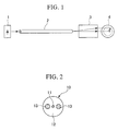
- An example of the cross section of the PANDA type optical fiber in its longitudinal direction is shown in FIG. 2.
- the PANDA type optical fiber 10 which is an example of a polarization plane preserving optical fiber, includes a core 11, a clad 12, and stress imparting parts 13. Since the thermal expansion coefficient of each of the stress imparting parts 13, which is made of a silica glass doped with boron oxide, is a few times larger than that of a silica glass that does not include boron oxide, it shrinks when being subjected to a drawing process. At that time, one stress which acts to pull the core 11 in the direction connecting the two stress imparting parts 13 and another stress which acts to compress the core 11 in the vertical direction with respect to the above-mentioned stress are generated and maintained in the fiber. When these different stress are added, the refractive index of the optical fiber varies in the direction connecting the two stress imparting parts 13 and in the vertical direction thereto.
- the velocity of light propagating through the PANDA type optical fiber is varied. That is, the velocity of light which propagates through the PANDA type optical fiber 10 in the direction connecting the stress imparting parts 13 is slow, and this is called a slow axis or X-axis. On the other hand, the velocity of light which propagates through the PANDA type optical fiber 10 in the vertical direction with respect to the X-axis is fast, and this is called a fast axis or Y-axis.
- the viscosity of the stress imparting part 13 of the PANDA type optical fiber is smaller than that of the clad 12 which surrounds the stress imparting part 13, it is not easy to produce a core 11 having an ideal circular cross section, and usually, a non-circular cross section thereof tends to be produced during the fiber forming process at high temperature. If the cross section of the core 11 is non-circular, the degree of connection loss is increased when connecting these optical fibers.
- a single mode fiber such as a polarization plane preserving optical fiber
- light power is also propagated to portions of the clad 12 in the vicinity of the core 11.
- the magnitude of propagation towards the clad 12 is exponentially decreased, and as far as the single mode fiber is concerned, the mode field diameter (MFD), which expresses the degree of propagation of the light power in the optical fiber, has an important meaning as compared with a core size, which indicates a physical boundary in relation to the distribution of refractive index. Accordingly, it is thought that the connection characteristic of a polarization plane preserving optical fiber is greatly effected by the degree of non-circularity of the mode field diameter. Therefore, it is necessary to determine the degree of circularity of the mode field diameter which is sufficient to obtain a polarization plane preserving optical fiber having excellent connection properties.
- the object of the present invention includes providing a polarization plane preserving optical fiber having a low connection loss by minimizing the degree of non-circularity of the mode field diameter.
- the core non-circularity ratio of the optical fiber which is defined as a value obtained by dividing the difference between the diameter of a circumscribing circle and that of an inscribing circle of the core by the diameter of the core, is about 20% or less.
- the optical fiber for preserving the plane of polarization is a PANDA type optical fiber.
- FIG. 1 is a diagram showing an example of a device for measuring the mode field diameter, which is a quantity having an influence on the connection loss of a polarization plane preserving optical fiber.
- the numeral 1 indicates a laser light source
- the numeral 2 indicates a polarization plane preserving optical fiber, which is the optical fiber to be measured and may be, for instance, a PANDA type optical fiber
- the numeral 3 indicates a light beam amplifying device which includes a lens system.
- the LP 01 mode emitted from the laser light source 1 incident on an end portion of the polarization plane preserving optical fiber 2 propagates through the optical fiber 2.
- the light then exits from the other end of the polarization plane preserving optical fiber 2 to enter the light beam amplifying device 3.
- the light beam amplifying device 3 amplifies the light beam from the polarization plane preserving optical fiber 2, and the amplified light beam is received by an infrared camera from which its two-dimensional light intensity distribution is output as an image 4.
- the polarization plane preserving optical fiber 2 has an ideal axial symmetry, the light intensity distribution thereof output as the image 4 forms concentric circles, and hence, the radius r of the image 4 is the same in any directions.
- the polarization plane preserving optical fiber 2 produced does not have an ideal axial symmetry and its waveguide portion has a non-circular cross-section. Accordingly, the radius r of the image 4 is dispersed and not the same. Using the maximum and minimum values of the radius r, it is possible to calculate the mode field diameter 2w according to the equation (1):
- f(r) indicates an electric field distribution
- the square of the electric field f 2 is proportional to the light power.
- MFD indicates a mode field diameter
- Ma indicates the maximum value of the mode field diameter
- Mb indicates the minimum value of the mode field diameter
- Table 1 shows the mode field diameter non-circularity ratio, the core non-circularity ratio, and the core eccentricity amount of the polarization plane preserving optical fibers having a relatively large degree of core non-circularity that exceeds about 15%.
- the non-circularity of the core is considered to be caused by the viscosity of the stress imparting part which is smaller than that of the clad in the fiber forming process.
- the core non-circularity ratio may be defined as a value obtained by dividing the difference between the diameter of a circumscribing circle and that of an inscribing circle of the core by the core diameter.
- the core eccentricity amount may be defined as the distance between the center of the core and that of the clad.
- the mode field diameter non-circularity ratio may be defined as a value which is calculated based on the mode field diameter measured when light having the wavelength of 1550 nm is input.
- Table 2 shows connection loss generated when two of the polarization plane preserving optical fibers shown in Table 1 were connected.
- the wavelength of light used for the measurements was 1550 nm, and the measurements were carried out by rotating a connection surface of one of the optical fibers to be connected by 90° for each measurement.
- connection loss is because, as mentioned above, the measurements were carried out while rotating the connection surface of the fiber, and the connection loss is small when the directions of non-circularity of the mode field diameter are matched. The connection loss is increased as the directions of the mode field diameter are shifted.
- connection loss is 0.13 dB even when the core non-circularity ratio of the polarization plane preserving optical fiber to be connected is about 20% if the mode field diameter non-circularity ratio is about 3.2% or less for the connection of the polarization plane preserving optical fibers of the combination numbers 1-12. Accordingly, taking into account the allowable limit of ordinary optical fibers of 0.2 - 0.3 dB, the connection loss is considered to be excellent.
- the core non-circularity ratios of the polarization plane preserving optical fiber thereof are larger than 25% and the mode field diameter non-circularity ratios are 4.5% or greater.
- the maximum connection loss is greater than 0.5 dB, and this value is much larger than the above-mentioned allowable limit of 0.2 - 0.3 dB. Accordingly, these fibers are not suitable for a practical use.
- a polarization plane preserving optical fiber of small connection loss may be produced by making the mode field diameter non-circular ratio of the fiber to be about 3.2% or less.
- a base material having a small core non-circular ratio is used and the tension of the fibers are adjusted in the fiber forming process.
- the core non-circularity ratio of a polarization plane preserving optical fiber to be 20% or less.
- the wavelength of light is not limited to 1550 nm. Since the mode field diameter expresses the degree of light power to propagate through the optical fiber at a wavelength used, the object of the invention can be achieved if the mode field diameter non-circularity ratio in the wavelength region used is 3.5% or less.
- PANDA type optical fiber is used as an example in the above explanation, it is not limited as such and other types of polarization plane preserving optical fibers having a stress imparting part disposed around a core may be used according to the present invention.
- a polarization plane preserving optical fiber having a small connection loss may be produced by decreasing the mode field diameter non-circularity of the polarization plane preserving optical fiber to about 3.2% or less.
Landscapes
- Physics & Mathematics (AREA)
- General Physics & Mathematics (AREA)
- Optics & Photonics (AREA)
- Optical Fibers, Optical Fiber Cores, And Optical Fiber Bundles (AREA)
- Optical Couplings Of Light Guides (AREA)
- Mechanical Coupling Of Light Guides (AREA)
Applications Claiming Priority (2)
| Application Number | Priority Date | Filing Date | Title |
|---|---|---|---|
| JP2001210648A JP2003029072A (ja) | 2001-07-11 | 2001-07-11 | 偏波面保存型光ファイバ |
| JP2001210648 | 2001-07-11 |
Publications (2)
| Publication Number | Publication Date |
|---|---|
| EP1275990A2 true EP1275990A2 (de) | 2003-01-15 |
| EP1275990A3 EP1275990A3 (de) | 2005-03-02 |
Family
ID=19046084
Family Applications (1)
| Application Number | Title | Priority Date | Filing Date |
|---|---|---|---|
| EP02290197A Ceased EP1275990A3 (de) | 2001-07-11 | 2002-01-29 | Polarisationserhaltende optische Faser |
Country Status (4)
| Country | Link |
|---|---|
| US (1) | US6597847B2 (de) |
| EP (1) | EP1275990A3 (de) |
| JP (1) | JP2003029072A (de) |
| CN (1) | CN1174269C (de) |
Families Citing this family (3)
| Publication number | Priority date | Publication date | Assignee | Title |
|---|---|---|---|---|
| JP2003279780A (ja) * | 2002-01-15 | 2003-10-02 | Sumitomo Electric Ind Ltd | 光ファイバ、光ファイバテープ、光ケーブル及び光ファイバ付き光コネクタ |
| JP3903987B2 (ja) | 2002-03-04 | 2007-04-11 | 住友電気工業株式会社 | 偏波保持光ファイバ製造方法 |
| DK4292990T3 (da) * | 2021-02-12 | 2025-12-08 | Sumitomo Electric Industries | Polarisationsbevarende optisk fiber og fremgangsmåde til fremstilling af polarisationsbevarende optisk fiber |
Family Cites Families (18)
| Publication number | Priority date | Publication date | Assignee | Title |
|---|---|---|---|---|
| JPS5992929A (ja) * | 1982-11-17 | 1984-05-29 | Nippon Telegr & Teleph Corp <Ntt> | 偏波保持光フアイバの製造方法 |
| JPS62148333A (ja) * | 1985-12-23 | 1987-07-02 | Sumitomo Electric Ind Ltd | 定偏波光フアイバの製造方法 |
| JPS63194207A (ja) | 1987-02-09 | 1988-08-11 | Nippon Telegr & Teleph Corp <Ntt> | 絶対単一偏波光フアイバ |
| JPH01222208A (ja) | 1988-03-02 | 1989-09-05 | Fujikura Ltd | 偏波保持光ファイバおよびこれを製造するためのファイバ母材 |
| JPH01314209A (ja) * | 1988-06-14 | 1989-12-19 | Sumitomo Electric Ind Ltd | 定偏波光ファイバ |
| US4896942A (en) * | 1989-02-03 | 1990-01-30 | Minnesota Mining And Manufacturing Company | Polarization-maintaining optical fiber |
| JPH0467105A (ja) | 1990-07-09 | 1992-03-03 | Nippon Telegr & Teleph Corp <Ntt> | 偏波保持光ファイバ |
| US5179603A (en) * | 1991-03-18 | 1993-01-12 | Corning Incorporated | Optical fiber amplifier and coupler |
| JP3088828B2 (ja) * | 1992-03-16 | 2000-09-18 | 古河電気工業株式会社 | 導波路型光デバイス接続用光ファイバ |
| JPH0624780A (ja) * | 1992-07-10 | 1994-02-01 | Furukawa Electric Co Ltd:The | 光ファイバ用母材の製造方法 |
| JPH0680434A (ja) * | 1992-08-31 | 1994-03-22 | Furukawa Electric Co Ltd:The | 光ファイバ用母材の製造方法 |
| JPH06242336A (ja) * | 1993-02-12 | 1994-09-02 | Furukawa Electric Co Ltd:The | 光ファイバ |
| JPH07242435A (ja) * | 1994-03-07 | 1995-09-19 | Shin Etsu Chem Co Ltd | 光ファイバ用多孔質ガラス母材の製造方法 |
| JPH0996729A (ja) * | 1994-09-14 | 1997-04-08 | Furukawa Electric Co Ltd:The | 光ファイバの製造方法 |
| JP3497298B2 (ja) * | 1995-10-23 | 2004-02-16 | 株式会社フジクラ | 光ファイバフィルタ |
| US5868815A (en) * | 1997-02-20 | 1999-02-09 | Lucent Technologies Inc. | Method of making an optical fiber by blowing on a preform tube to enhance collapse |
| JP2000233937A (ja) * | 1999-02-17 | 2000-08-29 | Nippon Telegr & Teleph Corp <Ntt> | 光ファイバの製造方法 |
| US6463195B1 (en) * | 1999-05-31 | 2002-10-08 | Fujikura Ltd. | Method of manufacturing polarization-maintaining optical fiber coupler |
-
2001
- 2001-07-11 JP JP2001210648A patent/JP2003029072A/ja active Pending
-
2002
- 2002-01-25 US US10/057,069 patent/US6597847B2/en not_active Expired - Lifetime
- 2002-01-29 EP EP02290197A patent/EP1275990A3/de not_active Ceased
- 2002-02-24 CN CNB021062625A patent/CN1174269C/zh not_active Expired - Lifetime
Non-Patent Citations (3)
| Title |
|---|
| RASHLEIGH S C: "Origins and control of polarization effects in single-mode fibers" JOURNAL OF LIGHTWAVE TECHNOLOGY, vol. 1, no. 2, 1 June 1983 (1983-06-01), pages 312-331, XP002125684 USA * |
| YAMADA,H, HANAFUSA, H: "Mode shape convertor produced by the thermal diffusion of different dopants" IEEE PHOTONICS TECHNOLOGY LETTERS, vol. 6, no. 4, 1 April 1994 (1994-04-01), pages 531-533, XP000446616 NEW YORK * |
| YOKOTA H., OKITSU E. ET AL.: "Design of polarization-maintaining optical fiber suitable for thermally-diffused expanded core techniques" IEICE TRANSACTIONS ON COMMUNICATIONS E, vol. 80, no. 4B, 1 April 1997 (1997-04-01), pages 516-521, XP000721824 * |
Also Published As
| Publication number | Publication date |
|---|---|
| EP1275990A3 (de) | 2005-03-02 |
| CN1174269C (zh) | 2004-11-03 |
| US6597847B2 (en) | 2003-07-22 |
| JP2003029072A (ja) | 2003-01-29 |
| CN1396466A (zh) | 2003-02-12 |
| US20030086669A1 (en) | 2003-05-08 |
Similar Documents
| Publication | Publication Date | Title |
|---|---|---|
| US7289687B2 (en) | Polarization-maintaining optical fiber | |
| US10545290B2 (en) | Polymer clad fiber for evanescent coupling | |
| EP0299603B1 (de) | Modusfeldmodifizierender faseroptischer Koppler | |
| US4447127A (en) | Low loss single mode fiber | |
| EP2626730B1 (de) | Polarisationserhaltende glasfaser | |
| EP3635459B1 (de) | Optische kopplerarrays | |
| AU2001246932B2 (en) | Optical fiber | |
| US20160097903A1 (en) | Skew managed multi-core optical fiber interconnects | |
| US7050672B1 (en) | Polarization-maintaining optical fiber and polarization-maintaining optical fiber component | |
| US7215860B2 (en) | Optical transmission fiber with a glass guiding cladding | |
| US20130287338A1 (en) | Optical Couplers And Methods For Making Same | |
| USRE38586E1 (en) | Fiber optic coupler exhibiting low nonadiabatic loss | |
| CN101231368A (zh) | 用于互连不同光纤的光纤设备和方法 | |
| Sharma et al. | Analysis of silica based single-mode fiber doped with germanium at different transmission window | |
| US6970632B2 (en) | Solid type single polarization fiber and apparatus | |
| US6597847B2 (en) | Optical fiber for preserving plane of polarization | |
| Francois et al. | Design of monomode quadruple-clad fibres | |
| US20240345325A1 (en) | Photonic lanterns comprising optical fibers having up-down doped claddings | |
| Guezennec et al. | Efficient single-mode operation in a 10 dB/m absorption very-large-mode-area ytterbium-doped optical fiber via curvature-induced mode filtering | |
| US20030035630A1 (en) | Thermally diffused multi-core waveguide | |
| RU2627018C1 (ru) | Радиационно-стойкий одномодовый световод с большим линейным двулучепреломлением для волоконно-оптического гироскопа | |
| CN104520742A (zh) | 具有grin 光纤的波长不敏感扩展光束 | |
| US20020136508A1 (en) | Method for making splices between two optical fibres which are different from each other | |
| US20240004152A1 (en) | Few mode optical fibers with reduced mode coupling and low birefringence | |
| JP2006208755A (ja) | 光送信器 |
Legal Events
| Date | Code | Title | Description |
|---|---|---|---|
| PUAI | Public reference made under article 153(3) epc to a published international application that has entered the european phase |
Free format text: ORIGINAL CODE: 0009012 |
|
| 17P | Request for examination filed |
Effective date: 20020202 |
|
| AK | Designated contracting states |
Kind code of ref document: A2 Designated state(s): AT BE CH CY DE DK ES FI FR GB GR IE IT LI LU MC NL PT SE TR |
|
| AX | Request for extension of the european patent |
Free format text: AL;LT;LV;MK;RO;SI |
|
| PUAL | Search report despatched |
Free format text: ORIGINAL CODE: 0009013 |
|
| AK | Designated contracting states |
Kind code of ref document: A3 Designated state(s): AT BE CH CY DE DK ES FI FR GB GR IE IT LI LU MC NL PT SE TR |
|
| AX | Request for extension of the european patent |
Extension state: AL LT LV MK RO SI |
|
| RIC1 | Information provided on ipc code assigned before grant |
Ipc: 7G 02B 6/10 B Ipc: 7G 02B 6/17 A |
|
| AKX | Designation fees paid |
Designated state(s): DE FR GB IT |
|
| 17Q | First examination report despatched |
Effective date: 20050822 |
|
| STAA | Information on the status of an ep patent application or granted ep patent |
Free format text: STATUS: THE APPLICATION HAS BEEN REFUSED |
|
| 18R | Application refused |
Effective date: 20081106 |