EP1276005B1 - Caméra et dispositif d'obturateur - Google Patents
Caméra et dispositif d'obturateur Download PDFInfo
- Publication number
- EP1276005B1 EP1276005B1 EP02254037A EP02254037A EP1276005B1 EP 1276005 B1 EP1276005 B1 EP 1276005B1 EP 02254037 A EP02254037 A EP 02254037A EP 02254037 A EP02254037 A EP 02254037A EP 1276005 B1 EP1276005 B1 EP 1276005B1
- Authority
- EP
- European Patent Office
- Prior art keywords
- lever
- delay
- shutter
- switch
- projection
- Prior art date
- Legal status (The legal status is an assumption and is not a legal conclusion. Google has not performed a legal analysis and makes no representation as to the accuracy of the status listed.)
- Expired - Lifetime
Links
- 230000007246 mechanism Effects 0.000 claims description 74
- 230000014759 maintenance of location Effects 0.000 claims description 58
- 230000000903 blocking effect Effects 0.000 claims description 27
- 230000005540 biological transmission Effects 0.000 claims description 20
- 238000004804 winding Methods 0.000 claims description 10
- 230000000994 depressogenic effect Effects 0.000 claims description 7
- 230000004044 response Effects 0.000 claims description 7
- 230000000717 retained effect Effects 0.000 claims description 5
- 210000000078 claw Anatomy 0.000 description 10
- 210000003423 ankle Anatomy 0.000 description 7
- 239000003990 capacitor Substances 0.000 description 7
- 230000035939 shock Effects 0.000 description 4
- 238000000034 method Methods 0.000 description 3
- 230000002093 peripheral effect Effects 0.000 description 3
- 230000008569 process Effects 0.000 description 3
- 125000006850 spacer group Chemical group 0.000 description 3
- XEEYBQQBJWHFJM-UHFFFAOYSA-N Iron Chemical compound [Fe] XEEYBQQBJWHFJM-UHFFFAOYSA-N 0.000 description 2
- 230000008859 change Effects 0.000 description 2
- 238000005286 illumination Methods 0.000 description 2
- 238000004519 manufacturing process Methods 0.000 description 2
- 229910052754 neon Inorganic materials 0.000 description 2
- GKAOGPIIYCISHV-UHFFFAOYSA-N neon atom Chemical compound [Ne] GKAOGPIIYCISHV-UHFFFAOYSA-N 0.000 description 2
- 238000004064 recycling Methods 0.000 description 2
- 238000010276 construction Methods 0.000 description 1
- 238000003780 insertion Methods 0.000 description 1
- 230000037431 insertion Effects 0.000 description 1
- 229910052742 iron Inorganic materials 0.000 description 1
- 239000000463 material Substances 0.000 description 1
- 238000005259 measurement Methods 0.000 description 1
- 230000003287 optical effect Effects 0.000 description 1
- 230000001105 regulatory effect Effects 0.000 description 1
- 238000005476 soldering Methods 0.000 description 1
- 230000001360 synchronised effect Effects 0.000 description 1
Images


Classifications
-
- G—PHYSICS
- G03—PHOTOGRAPHY; CINEMATOGRAPHY; ANALOGOUS TECHNIQUES USING WAVES OTHER THAN OPTICAL WAVES; ELECTROGRAPHY; HOLOGRAPHY
- G03B—APPARATUS OR ARRANGEMENTS FOR TAKING PHOTOGRAPHS OR FOR PROJECTING OR VIEWING THEM; APPARATUS OR ARRANGEMENTS EMPLOYING ANALOGOUS TECHNIQUES USING WAVES OTHER THAN OPTICAL WAVES; ACCESSORIES THEREFOR
- G03B7/00—Control of exposure by setting shutters, diaphragms or filters, separately or conjointly
- G03B7/003—Control of exposure by setting shutters, diaphragms or filters, separately or conjointly setting of both shutter and diaphragm
-
- G—PHYSICS
- G03—PHOTOGRAPHY; CINEMATOGRAPHY; ANALOGOUS TECHNIQUES USING WAVES OTHER THAN OPTICAL WAVES; ELECTROGRAPHY; HOLOGRAPHY
- G03B—APPARATUS OR ARRANGEMENTS FOR TAKING PHOTOGRAPHS OR FOR PROJECTING OR VIEWING THEM; APPARATUS OR ARRANGEMENTS EMPLOYING ANALOGOUS TECHNIQUES USING WAVES OTHER THAN OPTICAL WAVES; ACCESSORIES THEREFOR
- G03B7/00—Control of exposure by setting shutters, diaphragms or filters, separately or conjointly
- G03B7/08—Control effected solely on the basis of the response, to the intensity of the light received by the camera, of a built-in light-sensitive device
- G03B7/081—Analogue circuits
- G03B7/085—Analogue circuits for control of aperture
-
- G—PHYSICS
- G03—PHOTOGRAPHY; CINEMATOGRAPHY; ANALOGOUS TECHNIQUES USING WAVES OTHER THAN OPTICAL WAVES; ELECTROGRAPHY; HOLOGRAPHY
- G03B—APPARATUS OR ARRANGEMENTS FOR TAKING PHOTOGRAPHS OR FOR PROJECTING OR VIEWING THEM; APPARATUS OR ARRANGEMENTS EMPLOYING ANALOGOUS TECHNIQUES USING WAVES OTHER THAN OPTICAL WAVES; ACCESSORIES THEREFOR
- G03B7/00—Control of exposure by setting shutters, diaphragms or filters, separately or conjointly
- G03B7/08—Control effected solely on the basis of the response, to the intensity of the light received by the camera, of a built-in light-sensitive device
- G03B7/091—Digital circuits
- G03B7/095—Digital circuits for control of aperture
-
- G—PHYSICS
- G03—PHOTOGRAPHY; CINEMATOGRAPHY; ANALOGOUS TECHNIQUES USING WAVES OTHER THAN OPTICAL WAVES; ELECTROGRAPHY; HOLOGRAPHY
- G03B—APPARATUS OR ARRANGEMENTS FOR TAKING PHOTOGRAPHS OR FOR PROJECTING OR VIEWING THEM; APPARATUS OR ARRANGEMENTS EMPLOYING ANALOGOUS TECHNIQUES USING WAVES OTHER THAN OPTICAL WAVES; ACCESSORIES THEREFOR
- G03B9/00—Exposure-making shutters; Diaphragms
- G03B9/02—Diaphragms
- G03B9/04—Single movable plate with two or more apertures of graded size, e.g. sliding plate or pivoting plate
-
- G—PHYSICS
- G03—PHOTOGRAPHY; CINEMATOGRAPHY; ANALOGOUS TECHNIQUES USING WAVES OTHER THAN OPTICAL WAVES; ELECTROGRAPHY; HOLOGRAPHY
- G03B—APPARATUS OR ARRANGEMENTS FOR TAKING PHOTOGRAPHS OR FOR PROJECTING OR VIEWING THEM; APPARATUS OR ARRANGEMENTS EMPLOYING ANALOGOUS TECHNIQUES USING WAVES OTHER THAN OPTICAL WAVES; ACCESSORIES THEREFOR
- G03B9/00—Exposure-making shutters; Diaphragms
- G03B9/08—Shutters
- G03B9/10—Blade or disc rotating or pivoting about axis normal to its plane
Definitions
- the present invention relates to a camera and shutter device. More particularly, the present invention relates to a camera in which an aperture stop is changed over according to object brightness, and an exposure is taken after the aperture stop is set, and a shutter device.
- a lens-fitted photo film unit is known in the field of photograph as a camera of simple type, and pre-loaded with photo film in the course of manufacture.
- a lens in the lens-fitted photo film unit is a fixed focus type for the purpose of reducing a cost and structure.
- a shutter in the lens-fitted photo film unit is a knocking type in which a shutter blade opens and shuts upon knocking operation, and of which a shutter speed is fixed.
- brightness of a photographic object may be totally different between various types of scene to be photographed. The brightness may be very low because of weak illumination in an indoor scene, or very high because of strong illumination in an outdoor scene.
- An exposure amount must be adjusted for the purpose of an exposure in any level of brightness.
- There has been a suggested lens-fitted photo film unit in which a photometric circuit is incorporated for measuring object brightness, and an exposure amount can be adjusted by changing over an aperture stop mechanism according to the measured object brightness.
- the aperture stop changer device includes CdS element, solar cell or other photometric elements for measuring light from a photographic object to obtain object brightness.
- the object brightness is compared with reference brightness level, to drive a solenoid to set an aperture stop plate into or out of a photographic light path automatically.
- the measurement of object brightness is synchronized with turning on of the photometric switch by means of switching member movable in response to depression of a shutter release button.
- a widely used type of the photometric switch is a leaf switch because of a simple structure and a low cost.
- a pair of switch segments constitute the leaf switch, have conductivity and flexibility. A first one of the segments is depressed and caused to contact a second one of those, to turn on the photometric switch. When those segments are away from one another, the photometric switch is turned off.
- the photometric switch in a form of leaf switch is turned on accidentally upon occurrence of external shock or vibration to a camera body.
- the photometric circuit and solenoid may be actuated in connection with the photometric switch.
- EP 1096308 discloses a camera including a depressible shutter release button, and a shutter mechanism for being released in response to depression of the shutter release button, to provide an exposure to a photo film, the camera comprising: a photometric circuit for measuring object brightness; an aperture stop mechanism for setting a selected one of plural stop openings according to the object brightness; and a photometric switch, including first and second switch segments for being turned on when pressed, to supply said photometric circuit with power.
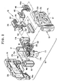
- a lens-fitted photo film unit 10 is illustrated.
- a main body 11 in the lens-fitted photo film unit 10 includes various elements for taking exposures, and is provided with an electronic flash unit 12.
- a front cover 13 and a rear cover 14 are fitted to cover the front and rear of the main body 11 and the flash unit 12.
- An exposure unit 15 or mechanical unit is disposed in the center of the main body 11.
- the flash unit 12 is disposed beside the exposure unit 15.
- a cassette holder chamber 11a and a photo film holder chamber 11b between which the exposure unit 15 is disposed.
- a photo film cassette 16 is inserted in the cassette holder chamber 11a.
- a photo film 17 is drawn from the photo film cassette 16, wound in a roll form and set in the photo film holder chamber 11b in the course of manufacture.
- a front opening 21 In the front cover 13 are formed a front opening 21, a viewfinder objective window 22, a flash emitter window 23, a photometric window 24, an opening 25 and a second photometric window 26 for flash light control.
- a taking lens 20 appears in the front opening 21.
- Bottom lids 14a and 14b are formed with the rear cover 14, and close lower openings of the cassette holder chamber 11a and the photo film holder chamber 11b. The bottom lid 14a is opened at the time of removing the photo film cassette 16 containing the photo film 17 after exposures.
- an opening 28 In upper portions of the front cover 13 and the rear cover 14, there are formed an opening 28, a frame counter window 29 and a readiness indicator window 31.
- a shutter release button 27 appears in the opening 28.
- a light guide 30 for optically guiding light is movable out of the readiness indicator window 31.
- a winder wheel 35 is disposed on an upper wall of the cassette holder chamber 11a. A portion of the winder wheel 35 protrudes through the rear cover 14 toward the rear. A shaft portion (not shown) is formed to protrude from a lower surface of the winder wheel 35. A spool 16a in the photo film cassette 16 is engaged with the shaft portion. The winder wheel 35 is rotated at each time after taking one exposure, to move the photo film 17 toward the inside of the photo film cassette 16 by one frame.
- An operation button 46 is disposed in front of the flash circuit board 39.
- a support plate 45 keeps the operation button 46 slidable up and down.
- a pushbutton portion 46a is included in the operation button 46, and inserted in the opening 25. The pushbutton portion 46a is slid manually by a user, to change over the operation button 46.
- Two set positions 47 are indicated with letters of OFF and ON, determined in portions of the front cover 13, and adapted for positioning the operation button 46 for setting a selected one of two states.
- the flash circuit When the pushbutton portion 46a is set in the OFF position, the flash circuit does not operate.
- a projection (not shown) on the rear of the operation button 46 pushes and turns on the flash charger switch 42.
- the flash circuit operates, to charge the main capacitor 36 and a trigger capacitor.
- voltage across the main capacitor 36 comes up to a prescribed voltage level, a neon tube or LED (light-emitting diode) is driven to emit light.
- the light emitted by the neon tube is guided through the light guide 30, and emanated by an outer end of the light guide 30, to inform a user of completion of the charging.
- the trigger capacitor When the sync switch 43 is turned on, the trigger capacitor is discharged. In response to this, charge having been stored in the main capacitor 36 passes through a flash discharge tube, to emit flash light toward a photographic object.
- the photometric element 38 receives reflected flash light behind the second photometric window 26 formed in the front cover 13. When an amount of received light comes up and reaches a predetermined amount, flash emission is quenched.
- a light-shielded tunnel 50 constitutes a base portion of the exposure unit 15, has an angular tubular shape protruding to the front. Elements are mounted on the light-shielded tunnel 50, including a shutter mechanism, photo film one-frame winding mechanism, viewfinder mechanism, frame counter disk and the like.
- An exposure aperture (not shown) is formed in a rear wall of the light-shielded tunnel 50.
- a frame or exposure region 17a is defined by the exposure aperture in the photo film 17 behind the same.
- a shutter opening 50a is formed in a front wall of the light-shielded tunnel 50.
- a shutter blade 51 and a lens unit 52 are secured to the light-shielded tunnel 50 in front of the shutter opening 50a.
- the shutter blade 51 includes a blade portion 51a, a driven portion 51b and a switching portion 51c.
- the blade portion 51a shuts the shutter opening 50a in an openable manner.
- a pivotal pin 50b protrudes from the front of the light-shielded tunnel 50.
- a pivotal hole 51d is formed in the shutter blade 51, receives the pivotal pin 50b to keep the shutter blade 51 rotatable.
- a return spring 53 is connected between the shutter blade 51 and the light-shielded tunnel 50, to bias the shutter blade 51 in a direction for the blade portion 51a to shut the shutter opening 50a.
- a shutter mechanism 75 includes a shutter drive lever 77 to be described later.
- a knocking arm 77a extends from the shutter drive lever 77 in such a manner that the driven portion 51b lies in a moving path of the knocking arm 77a.
- the knocking arm 77a knocks the driven portion 51b to the right.
- the shutter blade 51 rotates clockwise against the bias of the return spring 53, and comes to the open position where the shutter opening 50a is uncovered from the blade portion 51a.
- the bias of the return spring 53 causes the shutter blade 51 to rotate in the counterclockwise direction, before the blade portion 51a comes to the shut position when the shutter opening 50a is shut.
- the shutter opening 50a is opened and shut.
- the sync switch 43 of the flash unit 12 is disposed to extend into a path of movement of the switching portion 51c.
- the switching portion 51c pushes and turns on the sync switch 43.
- flash light is emitted in synchronism with movement of the shutter blade 51.
- a support member 57 is disposed behind the flash circuit board 39.
- a screw 56 fastens the support member 57 to the flash circuit board 39.
- a base board 55 supports the sync switch 43.
- a pair of bosses 55a are formed on the front of the base board 55, and fastened to the flash circuit board 39 indirectly with the support member 57. So the sync switch 43 is positioned at the moving path of the switching portion 51c by fixation with the screw 56.
- the lens unit 52 includes the taking lens 20, a base member 60, a spacer ring 61, a movable aperture stop plate 62, a stationary aperture stop ring 63, and a lens retention panel 64.
- An aperture stop mechanism is constituted by the movable aperture stop plate 62 and the stationary aperture stop ring 63.
- the taking lens 20 includes a front lens element 20a and a rear lens element 20b.
- a lens holder portion 60a is formed in the base member 60 in a tubular shape, and receives insertion of the rear lens element 20b, the spacer ring 61, the movable aperture stop plate 62, the stationary aperture stop ring 63 and the front lens element 20a in sequence.
- the lens retention panel 64 firmly retains those elements in the lens holder portion 60a.
- the movable aperture stop plate 62 has an L shape.
- a small stop opening 62a is formed in an end portion of the movable aperture stop plate 62.
- a driven arm 65 includes a connection portion 65a, to which the movable aperture stop plate 62 is secured fixedly.
- a support shaft 60b protrudes from the base member 60, and supports the movable aperture stop plate 62 and the driven arm 65 in a rotatable manner.
- a torsion coil spring 66 is connected with the driven arm 65, and biases the movable aperture stop plate 62 toward a small aperture position where the small stop opening 62a is set on in the photographic light path PL.
- a large stop opening 63a is formed in the stationary aperture stop ring 63, and has a greater diameter than that of the small stop opening 62a in the movable aperture stop plate 62.
- the movable aperture stop plate 62 is movable between the small aperture position and a large aperture position, and when in the small aperture position, sets the small stop opening 62a in the light path PL, and when in the large aperture position, sets the small stop opening 62a away from the light path PL.
- the aperture stop can be changed over between the large and small aperture stop states.
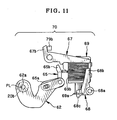
- An aperture stop changer mechanism 70 includes the CdS element 37, the photometric switch 44, a stop changer lever 67, a stopper lever 68 and a solenoid 69.
- the stop changer lever 67 constitutes an aperture stop plate shifter.
- the stopper lever 68 and the solenoid 69 constitute a movable stopper.
- a driven portion 65b is formed with the driven arm 65.
- a driving projection 67a projects from the stop changer lever 67, and contacts the driven portion 65b.
- an engagement projection 67b projects from the stop changer lever 67, and is retained by a transmission lever, which will be described later.
- a boss 55b projects from a rear of the base board 55, and is inserted in a hole in the stop changer lever 67, which is supported in a rotatable manner.
- a receiving hole 11c is formed in the main body 11.
- the boss 55b is combined with a torsion coil spring 71 and a holder 72, and inserted in the receiving hole 11c.
- the stop changer lever 67 is biased by the torsion coil spring 71 in the clockwise direction, for the driving projection 67a to push the driven portion 65b of the driven arm 65.
- the torsion coil spring 71 is provided with higher force than that of the torsion coil spring 66 biasing the movable aperture stop plate 62.
- the torsion coil spring 71 biases the movable aperture stop plate 62 in the counterclockwise direction against the bias of the torsion coil spring 66.
- the stopper lever 68 is disposed under an end of the stop changer lever 67.
- the stopper lever 68 includes a shaft 68a, a projection 68b, and an engagement portion 68c.
- a projection projects from the support member 57, and supports the stopper lever 68 in a rotatable manner.
- a plunger 69a of iron is provided in the solenoid 69, and is disposed behind the stopper lever 68.
- the engagement portion 68c is fitted on the plunger 69a.
- the stopper lever 68 is disposed to rotate in a manner coplanar with the stop changer lever 67 in response to turning on and off of the solenoid 69.
- the stopper lever 68 is movable between a disabling position and an enabling position, and when in the disabling position, sets the projection 68b to extend into a moving path of the stop changer lever 67 for retention, and when in the enabling position, is away from the moving path to enable the stop changer lever 67 to rotate.
- the solenoid 69 is constituted by the plunger 69a, a winding 69b, a holder frame 69c and a return spring 69d.
- the holder frame 69c is engaged with an engaging claw (not shown) formed with the support member 57.
- the plunger 69a is kept slidable in the winding 69b, and is biased by the return spring 69d toward a lower position where the plunger 69a protrudes downwards from the winding 69b.
- the solenoid 69 is a type in which powering of the winding 69b creates magnetic field to move back the plunger 69a to the inside of the winding 69b.
- the CdS element 37 measures object brightness, according to which a photometric circuit outputs a signal to control powering of the winding 69b.
- the photometric circuit is constituted by the CdS element 37, a switching transistor, the photometric switch 44 and the like.
- the CdS element 37 is a photoelectric element of which resistance changes according to brightness or intensity of incident light, and is disposed on the front of the flash circuit board 39 at the photometric window 24 in the front cover 13.
- the switching transistor (not shown) is connected at a line through which the battery 41 supplies the solenoid 69 with power, and causes a current to flow to the winding 69b selectively according to a level of a photometric value of the object brightness.
- the photometric switch 44 is fastened to the flash circuit board 39 by the support member 57.
- a switch gear 90 to be described later is connected with the shutter mechanism.
- a shifting projection 90d protrudes from the switch gear 90 in such a manner that the photometric switch 44 extends into a path of moving the shifting projection 90d.
- a predetermined level of the object brightness enough for actuating the solenoid 69 is predetermined according to the aperture stop value of the optical system. Also, it is possible that the movable aperture stop plate 62 is set away from the light path when in the normal state, and is set in the light path only when the object brightness is higher than the predetermined level.
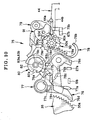
- the shutter mechanism 75 is secured to an upper side of the light-shielded tunnel 50, and includes a retention lever 76, the shutter drive lever 77, a delay lever 78 in a delay mechanism, a transmission lever 79 or charge lever, a cam 80 and a governor mechanism 81.
- the cam 80 includes a pivot 80a, a disk 82, a first cam portion 83a, a second cam portion 83b and a third cam portion 83c.
- a notch 82a is formed in the disk 82.
- the three cam portions 83a, 83b and 83c are formed with a lower side of the disk 82, and have a sector shape.
- a hole 50c is formed in the light-shielded tunnel 50, and receives the pivot 80a of the cam 80.
- a lower end portion of the pivot 80a is engaged with the engagement hole 84a.
- Perforations 17b are formed in the photo film 17.
- Plural teeth on the periphery of the sprocket wheel 84 are meshed with the perforations 17b.
- a pin 50d projects from the light-shielded tunnel 50, and supports the shutter drive lever 77 in a rotatable manner.
- a torsion coil spring 85 in the friction mechanism biases the shutter drive lever 77 in the counterclockwise direction.
- a hook 77b and a friction projection 77c are formed with the shutter drive lever 77 as well as the knocking arm 77a.
- the knocking arm 77a knocks the driven portion 51b of the shutter blade 51 to the right.
- the hook 77b contacts the first cam portion 83a.
- An end portion 78e extends from the delay lever 78.
- the friction projection 77c contacts the end portion 78e, to block rotation of the shutter drive lever 77 in the counterclockwise direction.
- a pivot 11d protrudes from the main body 11, and supports the retention lever 76 in a rotatable manner.
- a torsion coil spring 86 biases the retention lever 76 in the clockwise direction.
- the retention lever 76 are formed a retention claw 76a, a projection 76b, a release portion 76c and a retention claw 76d.
- a pivot 50e projects from the light-shielded tunnel 50, and supports the delay lever 78 in a rotatable manner.
- a torsion coil spring 87 biases the delay lever 78 in a counterclockwise direction.
- the delay lever 78 are formed a tooth train portion 78a, a second blocking pin 78b, a retention projection 78c and a cam follower 78d.
- the retention projection 78c contacts the projection 76b of the retention lever 76.
- the cam follower 78d contacts the third cam portion 83c.
- An arm extends from an end of the tooth train portion 78a, and is formed in a shape of a semi-circle.
- the second blocking pin 78b projects down from an end of the arm.
- the second blocking pin 78b blocks the second switch segment 44a at the time of not charging the shutter mechanism. So the second blocking pin 78b prevents the photometric switch 44 from being turned on accidentally. See Fig. 5.
- the end portion 78e comes into the rotating path of the friction projection 77c of the shutter drive lever 77, and retains the friction projection 77c so as to prevent the shutter drive lever 77 from swinging in the counterclockwise direction.
- An ankle 91 is combined with the switch gear 90, to constitute the governor mechanism 81.
- a pivot 50f protrudes from the light-shielded tunnel 50, and supports the switch gear 90 in a rotatable manner.
- the switch gear 90 is constituted by transmission gear portion 90a, an escapement wheel portion 90b, a retention ridge 90c, the shifting projection 90d and a blocking pin 90e as a first blocking mechanism.
- the transmission gear portion 90a is meshed with the tooth train portion 78a of the delay lever 78. Rotation of the delay lever 78 causes the switch gear 90 to rotate in a driven manner.
- the ankle 91 is engaged with the escapement wheel portion 90b, and regulates a rotational speed of the switch gear 90.
- the shifting projection 90d while the switch gear 90 rotates clockwise, pushes the second switch segment 44a to the first switch segment 44b and turns on the photometric switch 44. See Fig. 7.
- the blocking pin 90e blocks the second switch segment 44a to avoid turning on the photometric switch 44 accidentally. See Fig. 5.
- a pivot 50g projects from the light-shielded tunnel 50, and supports the transmission lever 79 in a rotatable manner.
- a torsion coil spring 92 biases the transmission lever 79 in the counterclockwise direction.
- An arm 79a and a retention projection 79b are formed with the transmission lever 79.
- a contact surface 79c is formed with an end portion of the arm 79a.
- a driven portion 79d is formed with a lower end portion of the arm 79a.
- the contact surface 79c contacts the second cam portion 83b, and also blocks rotation of the cam 80 in the clockwise direction at the time of shutter charging.
- the driven portion 79d contacts the retention ridge 90c of the switch gear 90.
- the retention projection 79b contacts the engagement projection 67b of the stop changer lever 67.
- the shutter mechanism 75 after being charged is illustrated.
- the retention lever 76 the retention claw 76a is engaged with the notch 82a to block rotation of the cam 80.
- the winder wheel 35 has peripheral teeth 35a, with which the retention claw 76d is engaged to block rotation of the winder wheel 35.
- the delay lever 78 is kept positioned as illustrated by engagement between the retention projection 78c and the projection 76b.
- the blocking pin 90e of the switch gear 90 contacts the second switch segment 44a to keep the photometric switch 44 turned off.
- the photometric switch 44 remains turned off even shock or vibration occurs to the photometric switch 44.
- the transmission lever 79 is prevented from rotating counterclockwise as the driven portion 79d contacts the retention ridge 90c of the switch gear 90.
- the engagement projection 67b of the stop changer lever 67 is prevented from moving toward the right.
- An end of the stop changer lever 67 is kept at a small distance from the projection 68b of the stopper lever 68.
- the transmission projection 27a moves from the position of the solid line to that of the phantom line. See Fig. 7.
- the shift of the transmission projection 27a pushes the release portion 76c to the right to rotate the retention lever 76 in the counterclockwise direction.
- the projection 76b comes away from the retention projection 78c to rotate the delay lever 78 in the counterclockwise direction.
- the switch gear 90 rotates in the clockwise direction.
- the retention ridge 90c is caused to come away from the driven portion 79d, to rotate the transmission lever 79 in the counterclockwise direction.
- the retention projection 79b moves from the position of the solid line to that of the phantom line, and comes away from the engagement projection 67b.
- the stop changer lever 67 rotates in the clockwise direction to a small extent. An end portion of the stop changer lever 67 contacts the projection 68b of the stopper lever 68.
- the shifting projection 90d depresses the second switch segment 44a to the first switch segment 44b, and turns on the photometric switch 44.
- the photometric circuit is operated to measure object brightness.
- the movable aperture stop plate 62 is kept in the small aperture position where the small stop opening 62a is set in the light path PL. If, in contrast, the measured object brightness is lower than the predetermined level, electric energy is applied to the solenoid 69.
- the plunger 69a is moved to the inside of the winding 69b to rotate the stopper lever 68 to the non-retention position.
- the stop changer lever 67 rotates clockwise.
- the driving projection 67a pushes the driven portion 65b to the left to rotate the driven arm 65 in the counterclockwise direction. Consequently, the movable aperture stop plate 62 swings to the large aperture position where the small stop opening 62a is away from the light path PL.
- the projection 76b of the retention lever 76 contacts the retention projection 78c, to retain the retention claw 76d in a position away from the peripheral teeth 35a.
- the contact surface 79c of the transmission lever 79 contacts and is retained by the second cam portion 83b.
- the knocking arm 77a of the shutter drive lever 77 is positioned to the right of the driven portion 51b of the shutter blade 51.
- the second blocking pin 78b of the delay lever 78 contacts the second switch segment 44a in the photometric switch 44 to turn off the photometric switch 44, and prevents the photometric switch 44 from turning on even upon occurrence of shock or vibration.
- the engagement projection 67b of the stop changer lever 67 is positioned as indicated by the solid line in Fig. 7, and retained by the retention projection 79b. If the aperture stop is changed over, the engagement projection 67b remains positioned as indicated by the phantom line in Fig. 7.
- the cam 80 When the winder wheel 35 is rotated for taking another exposure, the cam 80 is rotated in the counterclockwise direction by movement of the photo film 17. See Fig. 10. During rotation of the cam 80, the first cam portion 83a pushes the hook 77b to rotate the shutter drive lever 77 in the clockwise direction. Accordingly, the knocking arm 77a reaches to a position that is to the left of the driven portion 51b of the shutter blade 51.
- the third cam portion 83c pushes the cam follower 78d to rotate the delay lever 78 in the clockwise direction.
- the switch gear 90 rotates in the counterclockwise direction.
- the shifting projection 90d pushes the second switch segment 44a in the photometric switch 44 to raise the same to the position higher than that indicated by the solid line.
- the shifting projection 90d comes away from the second switch segment 44a, which returns to its original position.
- the second cam portion 83b pushes the contact surface 79c to rotate the transmission lever 79 in the clockwise direction.
- the retention projection 79b pushes the engagement projection 67b of the stop changer lever 67 and moves the same to a position that is sufficiently distant from the initial position on the left side.
- an end of the stop changer lever 67 is raised by the projection 68b of the stopper lever 68.
- the movable aperture stop plate 62 is set in the small aperture position where the small stop opening 62a is located in the light path PL. As the photometric circuit does not operate, the stopper lever 68 is in the retention position to block rotation of the stop changer lever 67.
- the cam 80 further rotates in the counterclockwise direction.
- the retention projection 78c comes away from the projection 76b to rotate the retention lever 76 in the clockwise direction.
- the retention claw 76a becomes engaged with the notch 82a.
- the retention claw 76d becomes engaged with the peripheral teeth 35a.
- the charge of the shutter mechanism is completed as illustrated in Fig. 5, to stand by for another exposure.
- the shifting projection 90d and the blocking pin 90e project from the escapement wheel portion 90b according to the above embodiment.
- the shifting projection 90d and the blocking pin 90e may project from positions in the transmission gear portion 90a at its middle height.
- the lens-fitted photo film unit with the structure according to the invention is described.
- the structure of the invention may be incorporated in a camera of any type.
- the photo film is IX240 type.
- the photo film used in the invention may be 135 type or any type of a strip shape.
- the feature of the friction mechanism is hereinafter described in detail, including the friction projection 77c and the torsion coil spring 85 for braking the delay lever 78 to determining sufficient delay time.
- the shutter release button 27 is depressed. When the delay time of a predetermined value lapses after the depression, the driven portion 51b of the shutter blade 51 is knocked by the knocking arm 77a toward the right.
- the end portion 78e enters a rotational path of the friction projection 77c after the shutter charging until a swing of the delay lever 78 at a predetermined phase difference.
- the end portion 78e retains the friction projection 77c and prevents the shutter drive lever 77 from rotating counterclockwise.
- the projection 76b is shifted away from the retention projection 78c to rotate the delay lever 78 by a predetermined phase difference.
- the end portion 78e is shifted away from the friction projection 77c to allow the shutter drive lever 77 to rotate.
- the time required after the depression of the shutter release button 27 until the swing of the delay lever 78 at a predetermined phase difference is determined as delay time additionally passed before the shutter releasing.
- the delay time is determined by a rotational speed of the delay lever 78.
- a pivot 50k supports the ankle 91 in a rotatable manner.
- the ankle 91 is engaged with the escapement wheel portion 90b in the switch gear 90.
- Projections 91a and 91b are included in the ankle 91, opposed to the switch gear 90, and become engaged with the escapement wheel portion 90b alternately.
- the ankle 91 regulates a rotational speed of the delay lever 78 by means of the switch gear 90.
- a friction mechanism for the delay lever 78 is constituted by the friction projection 77c and the torsion coil spring 85.
- the friction mechanism provides frictional force suitable for the bias of the torsion coil spring 85 when the friction projection 77c contacts the end portion 78e.
- the frictional force can regularize the rotational speed of the delay lever 78 in contrast with a construction without the friction mechanism, because the ankle 91 of a plastic material is too lightweight to control the delay time.
- the combination of the friction mechanism and the governor mechanism 81 therefore, keeps the delay time unchanged as the rotational speed of the delay lever 78 can be regulated at the constant speed level.
- the boss 55b supports the stop changer lever 67, which is disposed flush with a moving path of the driven portion 65b of the driven arm 65.
- the stop changer lever 67 swings between first and second angular positions, and when in the first angular position, is retained by the stopper lever 68 as illustrated in Fig. 6, and when in the second angular position, causes the driving projection 67a to push the driven portion 65b of the driven arm 65 as illustrated in Fig. 8.
- Each of the exposure unit 15, the flash unit 12 and the lens unit 52 is obtained from respective assembling processes, and is supplied to a process of assembling the lens-fitted photo film unit 10.
- elements are mounted on the light-shielded tunnel 50 in the exposure unit 15, including the shutter mechanism, the viewfinder mechanism and the frame counter mechanism.
- elements are mounted on the base member 60 in the lens unit 52, including the spacer ring 61, the movable aperture stop plate 62, the stationary aperture stop ring 63 and the lens retention panel 64.
- various elements are positioned on and soldered to the flash circuit board 39 in the flash unit 12, including the main capacitor 36, the CdS element 37, the photometric element 38, the flash charger switch 42, the sync switch 43, the photometric switch 44, the solenoid 69 and the like. Also, mechanical elements are secured to the flash unit 12, including the stop changer lever 67 and the stopper lever 68.
- the light-shielded tunnel 50 is secured to the main body 11 at first.
- the lens unit 52 is secured to the front of the light-shielded tunnel 50, to obtain the exposure unit 15.
- the boss 55b is inserted in the receiving hole 11c in the main body 11, to fasten the flash unit 12 to the exposure unit 15.
- the sync switch 43 is positioned in a moving path of the switching portion 51c of the shutter blade 51.
- the photometric switch 44 is positioned in a moving path of the shifting projection 90d.
- the stop changer lever 67 is positioned flush with a moving path of the driven portion 65b of the driven arm 65.
- the battery 41, the operation button 46 and the shutter release button 27 are positioned and secured.
- the photo film cassette 16 and the photo film 17 are inserted before the front cover 13 and the rear cover 14 are secured to the outside of the main body 11. Thus, the lens-fitted photo film unit 10 is obtained.
- the solenoid 69 is driven according to object brightness, to shift the movable aperture stop plate 62 into and out of the light path.
- the aperture stop changer mechanism 70 can have an externally operable button member, which can be moved to rotate the stop changer lever 67 for changing over the aperture stop.
- the actuator for changing over the aperture stop is the solenoid.
- a motor as an actuator can be used for shifting the movable aperture stop plate 62.
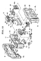
- An exposure aperture 102 is formed in the center of the main body 11 for defining one frame region in front of the photo film.
- the exposure aperture 102, the exposure unit 15 and the lens unit 52 are arranged in sequence along the light path PL.
- a retention hook 104 extends from the main body 11, and retains the exposure unit 15 to the main body 11.
- a retention hook 100 extends from the exposure unit 15, and retains the lens unit 52 to the exposure unit 15.
- the flash unit 12 is disposed beside the exposure unit 15.
- a retention hook 106 extends from the main body 11, and fastens the flash unit 12 to the main body 11.
- the movable aperture stop plate 62 may have a large stop opening in addition to the small stop opening 62a.
- the movable aperture stop plate 62 when set in the small aperture position, can set the small stop opening 62a in the light path PL, and when in the large aperture position, can set the large stop opening in the light path PL in place of the small stop opening 62a, so as to change over the large and small aperture stop states.
- a frame counter disk 110 and a retention panel 112 are secured to the light-shielded tunnel 50 in the exposure unit 15 in addition to the shutter blade 51, the shutter mechanism 75 and the viewfinder.
- the lens-fitted photo film unit 10 When development of the photo film is desired by a user after taking all exposures, the lens-fitted photo film unit 10 is forwarded to a photo laboratory.
- the bottom lid 14a is opened in the photo laboratory, to remove the cassette with the photo film.
- the photo film is processed, and subjected to producing photographic prints.
- the lens-fitted photo film unit 10 from which the cassette is removed is collected from a laboratory to a recycling factory. In the recycling factory, the front cover 13 and the rear cover 14 are removed. After this, the lens unit 52, the flash unit 12 and the exposure unit 15 are removed from the main body 11, and reused. There is no soldering between the lens unit 52, the flash unit 12 and the exposure unit 15 by any wires or boards.
- the retention hooks 100, 104 and 106 can be disengaged from one another to remove the lens unit 52, the flash unit 12 and the exposure unit 15 from the main body 11.
- the movable aperture stop plate 62 is movable into and out of a space between the front lens element 20a and the rear lens element 20b.
- a space may be defined behind the taking lens 20.
- the aperture stop changer mechanism 70 can have the movable aperture stop plate 62 movable into and out of the space.
- the lens-fitted photo film unit according to Figs. 13-15 does not include the blocking pin 90e and the second blocking pin 78b according to Figs. 4-12.
- the use of the triple unit structure according to the present invention is effective in the lens-fitted photo film unit including the blocking pin 90e and the second blocking pin 78b.
Landscapes
- Physics & Mathematics (AREA)
- General Physics & Mathematics (AREA)
- Diaphragms For Cameras (AREA)
- Exposure Control For Cameras (AREA)
- Camera Bodies And Camera Details Or Accessories (AREA)
- Structure And Mechanism Of Cameras (AREA)
Claims (11)
- Caméra, incluant :un bouton de déclenchement d'obturateur (27) à enfoncer ;un mécanisme obturateur (75) destiné à être déclenché en réponse à l'enfoncement dudit bouton de déclenchement d'obturateur, pour réaliser une exposition d'un film photographique (17) ;un circuit photométrique (37) pour mesurer la luminosité d'un objet ;un mécanisme d'arrêt d'ouverture (62, 63) pour fixer une ouverture choisie parmi une pluralité d'ouvertures d'arrêt (62a, 63a) en accord avec ladite luminosité de l'objet ;un commutateur photométrique (44) qui inclut un premier et un second segment de commutateur (44a, 44b) destinés à être mis en circuit lorsqu'ils sont appuyés, pour alimenter ledit circuit photométrique en puissance ;un premier mécanisme de blocage (90e) pour maintenir ledit second segment de commutateur (44a) de manière à empêcher un contact avec ledit premier segment de commutateur (44b) lors de la terminaison d'une opération de chargement dudit mécanisme d'obturateur, et pour libérer ledit second segment de commutateur par relâchement dudit maintien quand ledit bouton de déclenchement d'obturateur est enfoncé ;un mécanisme de passage (90d) pour presser ledit second segment de commutateur pour venir en contact avec ledit premier segment de commutateur après que ledit premier mécanisme de blocage ait libéré ledit maintien dudit second segment de commutateur ;un mécanisme à délai destiné à être passé à une position chargée par une opération de bobinage dudit film photographique (17), et à être passé à une position libérée en réponse audit enfoncement dudit bouton de déclenchement d'obturateur (27), pour actionner ledit mécanisme d'obturateur (75) ;un second mécanisme de blocage (78) pour maintenir ledit second segment de commutateur (44a) quand ledit mécanisme d'obturateur (75) est actionné de manière à empêcher audit second segment de commutateur de venir en contact avec ledit premier segment de commutateur (44b) jusqu'à un démarrage de ladite opération de chargement dudit mécanisme d'obturateur ;dans laquelle ledit premier mécanisme de blocage (90e) est déplacé en accord avec le passage dudit mécanisme de délai de manière à maintenir ledit second segment de commutateur (44a) pour empêcher un contact avec ledit premier segment de commutateur (44b) quand ledit mécanisme de délai est dans ladite position chargée, et relâcher ledit maintien dudit second segment de commutateur quand ledit mécanisme de délai est dans ladite position relâchée ; et
comprenant en outre une roue dentée de commutateur (90) pour tourner en accord avec le passage dudit mécanisme de délai ;
dans laquelle ledit premier mécanisme de blocage (90e) est une tige de blocage, ledit mécanisme de passage (90d) est une projection de passage, et ladite tige de blocage et ladite projection de passage sont formées de manière à se projeter depuis ladite roue dentée de commutateur (90). - Caméra selon la revendication 1, dans laquelle ledit premier segment de commutateur (44b) est décalé depuis un trajet de déplacement de ladite tige de blocage et de ladite projection de passage, et est dégagé vis-à-vis de celles-ci ;
ledit second segment de commutateur (44a) comprend une portion disposée dans ledit trajet de déplacement, possède des caractéristiques de ressort, est poussé par ladite projection de passage alors que ledit mécanisme de délai est passé entre ladite position chargée et ladite position libérée, et retourne ultérieurement à un état d'origine avec élasticité. - Caméra selon la revendication 2, dans laquelle ledit mécanisme de délai inclut une portion formant train denté (78a) ayant une pluralité de dents arrangées le long d'un arc ;
comprenant en outre une portion d'engrenage de transmission, formée avec ladite roue dentée de commutateur (90) et en engrènement avec ladite portion formant train denté (78a) en vue d'une rotation. - Caméra selon la revendication 3, dans laquelle ledit mécanisme de délai inclut un levier de délai (78) mobile en pivotement ;
ledit second mécanisme de blocage (78) est une seconde tige de blocage formé de manière à se projeter depuis ledit levier de délai. - Caméra selon la revendication 4, dans laquelle ladite roue dentée de commutateur (90) inclut en outre une portion de roue à échappement (90b) formée avec ladite portion d'engrenage de transmission, et présentant ladite tige de blocage et ladite projection de passage en projection depuis une périphérie d'elle-même ;
comprenant en outre un mécanisme de commande (81) en engrènement avec ladite portion de roue à échappement, pour maintenir un pivotement dudit levier de délai (78) à une vitesse régulière. - Caméra selon la revendication 5, comprenant en outre un levier de transmission (79) qui est mobile en pivotement, pour inverser ledit mécanisme d'arrêt d'ouverture (62, 63), dans laquelle ladite roue dentée de commutateur (90) inclut en outre un rebord de rétention (90c) ayant un rayon prédéterminé, pour retenir ledit levier de transmission quand ledit levier de délai (78) est dans ladite position chargée, et pour se dégager dudit levier de transmission quand ledit levier de délai est dans ladite position libérée, pour permettre d'inverser ledit mécanisme d'arrêt d'ouverture.
- Caméra selon la revendication 6, comprenant en outre un levier de rétention (76) pour transmettre le passage dudit bouton de déclenchement d'obturateur (27) audit levier de délai (78) ;
dans laquelle ledit levier de délai est capable de tourner entre ladite position chargée et ladite position libérée, et comprend une projection de rétention (78c),
quand ledit levier de délai se trouve dans chacune parmi ladite position libérée et ladite position chargée, ladite projection de rétention est retenue par ledit levier de rétention (76) ;
quand ledit levier de délai tourne vers ladite position libérée ou ladite position chargée, ladite projection de rétention est libérée par rapport audit levier de rétention (76). - Caméra selon la revendication 1, dans laquelle ledit mécanisme d'obturateur (75) inclut :un levier de délai (70) pour se déplacer depuis une position chargée vers une position libérée en réponse audit enfoncement dudit bouton de déclenchement d'obturateur (27), et pour atteindre ladite position libérée après écoulement d'un retard temporel ;un levier d'entraînement d'obturateur (70) pour se déplacer depuis une première position vers une seconde position quand ledit levier de délai atteint ladite position libérée ;une lame d'obturateur (51), entraînée par ledit levier d'entraînement d'obturateur qui se déplace vers ladite seconde position, pour ouvrir et pour fermer un trajet de lumière photographique (PL) ;comprenant en outre un mécanisme à friction (77c, 85) pour réaliser une opération de freinage sur ledit levier de délai par un contact à friction avec celui-ci, pour allonger ledit retard temporel.
- Caméra selon la revendication 8, comprenant en outre :un émetteur flash (40) pour appliquer une lumière flash à un objet photographié ;une carte à circuit flash (39) pour commander ledit émetteur flash ; etun actionneur d'arrêt d'ouverture (69), attaché à ladite carte à circuits flash, pour commander le passage dudit mécanisme d'arrêt d'ouverture (62, 63) entre ladite pluralité d'ouvertures d'arrêt (62a, 63a).
- Caméra selon la revendication 9, dans laquelle ledit mécanisme d'arrêt d'ouverture (62, 63) inclut :une large ouverture d'arrêt (63a) disposée derrière une lentille de prise de vue (20) de manière stationnaire ; etune plaque d'arrêt d'ouverture mobile (62), ayant une petite ouverture d'arrêt (62a) plus petite que ladite large ouverture d'arrêt, qui est mobile entre une position de grande ouverture et une position de petite ouverture, ladite plaque d'arrêt d'ouverture mobile, lorsqu'elle se trouve dans ladite position de grande ouverture, étant décalée d'une position derrière ladite lentille de prise de vue et, lorsqu'elle se trouve dans ladite position de petite ouverture, étant disposée derrière ladite lentille de prise de vue pour établir ladite ouverture d'arrêt de petite taille.
- Caméra selon la revendication 10, comprenant en outre :un corps principal (11) destiné à être chargé avec ledit film photographique (17) ;une ouverture d'exposition, formée dans ledit corps principal, pour créer une région exposée d'une trame dans ledit film photographique ;un tunnel (50) isolé vis-à-vis de la lumière, disposé en connexion avec une partie frontale de ladite ouverture d'exposition, pour couvrir ledit trajet lumineux photographique (PL), ledit tunnel (50) isolé vis-à-vis de la lumière ayant ledit mécanisme d'obturateur (75) attaché sur lui-même, pour constituer une unité d'exposition (15) conjointement avec celui-ci ; etune unité à lentille (52) comprenant ledit mécanisme d'arrêt d'ouverture (62, 63), et comprenant ladite lentille de prise de vue (20) disposée dans une partie frontale de celui-ci, pour introduire la lumière provenant dudit objet.
Priority Applications (2)
| Application Number | Priority Date | Filing Date | Title |
|---|---|---|---|
| EP05012418A EP1571488A2 (fr) | 2001-06-12 | 2002-06-11 | Appareil photographique et obturateur |
| EP05012417A EP1571487A2 (fr) | 2001-06-12 | 2002-06-11 | Appareil photographique et obturateur |
Applications Claiming Priority (8)
| Application Number | Priority Date | Filing Date | Title |
|---|---|---|---|
| JP2001177472A JP2002365694A (ja) | 2001-06-12 | 2001-06-12 | カメラのシャッタ機構 |
| JP2001177473 | 2001-06-12 | ||
| JP2001177471A JP2002365687A (ja) | 2001-06-12 | 2001-06-12 | カメラ |
| JP2001177473A JP2002365709A (ja) | 2001-06-12 | 2001-06-12 | カメラ |
| JP2001177471 | 2001-06-12 | ||
| JP2001177472 | 2001-06-12 | ||
| JP2001235305A JP2003043636A (ja) | 2001-08-02 | 2001-08-02 | カメラ |
| JP2001235305 | 2001-08-02 |
Related Child Applications (2)
| Application Number | Title | Priority Date | Filing Date |
|---|---|---|---|
| EP05012418A Division EP1571488A2 (fr) | 2001-06-12 | 2002-06-11 | Appareil photographique et obturateur |
| EP05012417A Division EP1571487A2 (fr) | 2001-06-12 | 2002-06-11 | Appareil photographique et obturateur |
Publications (3)
| Publication Number | Publication Date |
|---|---|
| EP1276005A2 EP1276005A2 (fr) | 2003-01-15 |
| EP1276005A3 EP1276005A3 (fr) | 2003-08-13 |
| EP1276005B1 true EP1276005B1 (fr) | 2007-01-17 |
Family
ID=27482327
Family Applications (3)
| Application Number | Title | Priority Date | Filing Date |
|---|---|---|---|
| EP05012418A Withdrawn EP1571488A2 (fr) | 2001-06-12 | 2002-06-11 | Appareil photographique et obturateur |
| EP02254037A Expired - Lifetime EP1276005B1 (fr) | 2001-06-12 | 2002-06-11 | Caméra et dispositif d'obturateur |
| EP05012417A Withdrawn EP1571487A2 (fr) | 2001-06-12 | 2002-06-11 | Appareil photographique et obturateur |
Family Applications Before (1)
| Application Number | Title | Priority Date | Filing Date |
|---|---|---|---|
| EP05012418A Withdrawn EP1571488A2 (fr) | 2001-06-12 | 2002-06-11 | Appareil photographique et obturateur |
Family Applications After (1)
| Application Number | Title | Priority Date | Filing Date |
|---|---|---|---|
| EP05012417A Withdrawn EP1571487A2 (fr) | 2001-06-12 | 2002-06-11 | Appareil photographique et obturateur |
Country Status (3)
| Country | Link |
|---|---|
| US (3) | US6701078B2 (fr) |
| EP (3) | EP1571488A2 (fr) |
| DE (1) | DE60217584T2 (fr) |
Families Citing this family (3)
| Publication number | Priority date | Publication date | Assignee | Title |
|---|---|---|---|---|
| JP2005077574A (ja) * | 2003-08-29 | 2005-03-24 | Sony Corp | 撮像装置 |
| JP2008116690A (ja) * | 2006-11-06 | 2008-05-22 | Fujifilm Corp | 発光装置付き機器のスイッチ装置およびレンズ付きフイルムユニット |
| US20080198589A1 (en) * | 2007-02-20 | 2008-08-21 | Giga-Byte Technology Co., Ltd. | Telecommunication device and illumination structure thereof |
Family Cites Families (7)
| Publication number | Priority date | Publication date | Assignee | Title |
|---|---|---|---|---|
| FR2037880A5 (fr) * | 1969-03-24 | 1970-12-31 | Agfa Gevaert Ag | |
| JPS5112107Y2 (fr) * | 1971-09-02 | 1976-04-01 | ||
| US4125848A (en) * | 1973-03-30 | 1978-11-14 | Canon Kabushiki Kaisha | Exposure control device for a single lens reflex camera |
| JPH04124236U (ja) * | 1991-04-25 | 1992-11-12 | 株式会社精工舎 | 閃光同調装置 |
| KR100665723B1 (ko) * | 1999-11-01 | 2007-01-09 | 후지 샤신 필름 가부시기가이샤 | 카메라용 노출 제어 장치 |
| US6442343B2 (en) * | 2000-05-25 | 2002-08-27 | Fuji Photo Film Co., Ltd. | Exposure control device for camera |
| US6561704B2 (en) * | 2001-06-14 | 2003-05-13 | Eastman Kodak Company | Camera with self-timer and timer for use in camera |
-
2002
- 2002-06-11 EP EP05012418A patent/EP1571488A2/fr not_active Withdrawn
- 2002-06-11 DE DE60217584T patent/DE60217584T2/de not_active Expired - Fee Related
- 2002-06-11 EP EP02254037A patent/EP1276005B1/fr not_active Expired - Lifetime
- 2002-06-11 EP EP05012417A patent/EP1571487A2/fr not_active Withdrawn
- 2002-06-12 US US10/166,682 patent/US6701078B2/en not_active Expired - Fee Related
-
2003
- 2003-04-22 US US10/419,792 patent/US6763185B2/en not_active Expired - Fee Related
- 2003-04-22 US US10/419,791 patent/US6738576B2/en not_active Expired - Fee Related
Also Published As
| Publication number | Publication date |
|---|---|
| US6701078B2 (en) | 2004-03-02 |
| EP1276005A3 (fr) | 2003-08-13 |
| DE60217584D1 (de) | 2007-03-08 |
| US20030206737A1 (en) | 2003-11-06 |
| EP1571487A2 (fr) | 2005-09-07 |
| DE60217584T2 (de) | 2007-10-11 |
| EP1276005A2 (fr) | 2003-01-15 |
| US20030206738A1 (en) | 2003-11-06 |
| EP1571488A2 (fr) | 2005-09-07 |
| US6763185B2 (en) | 2004-07-13 |
| US6738576B2 (en) | 2004-05-18 |
| US20020186973A1 (en) | 2002-12-12 |
Similar Documents
| Publication | Publication Date | Title |
|---|---|---|
| US3768387A (en) | Photographic camera having an electric timer device | |
| JPH095817A (ja) | レンズ付きフイルムユニット | |
| US6618561B2 (en) | Stop changing device for a camera | |
| EP1276005B1 (fr) | Caméra et dispositif d'obturateur | |
| US6442343B2 (en) | Exposure control device for camera | |
| US6816672B2 (en) | Lens-fitted photo film unit | |
| US6477325B1 (en) | Lens-fitted photo film unit with lens position changing device | |
| US6597870B2 (en) | Lens-fitted photo film unit having a stop changing device | |
| KR100496073B1 (ko) | 카메라 | |
| JP2001013636A (ja) | カメラ | |
| US6741806B2 (en) | Lens-fitted photo film unit and method for manufacturing lens-fitted photo film unit | |
| US6705775B2 (en) | Lens-fitted photo film unit provided with a stop-changing mechanism, and device for changing a stop | |
| US6701070B2 (en) | Aperture stop changing device for camera | |
| JP2002049075A (ja) | カメラの絞り切り替え装置 | |
| JP3850008B2 (ja) | レンズ付きフイルムユニット | |
| JP2003161979A (ja) | シャッタ装置及びこれを用いたカメラ | |
| JPH07146531A (ja) | レンズ付フィルムユニットとストロボトリガスイッチ及びプリント基板 | |
| JP2002365687A (ja) | カメラ | |
| US6397011B1 (en) | Camera with automatic stop change device | |
| JP2001147461A (ja) | カメラのシャッタ装置 | |
| JP2002365694A (ja) | カメラのシャッタ機構 | |
| JP2004078064A (ja) | レンズ付きフイルムユニットの製造方法 | |
| JPH037085B2 (fr) | ||
| JP2003295253A (ja) | カメラ | |
| JP2001133836A (ja) | カメラのシャッタ装置 |
Legal Events
| Date | Code | Title | Description |
|---|---|---|---|
| PUAI | Public reference made under article 153(3) epc to a published international application that has entered the european phase |
Free format text: ORIGINAL CODE: 0009012 |
|
| AK | Designated contracting states |
Kind code of ref document: A2 Designated state(s): AT BE CH CY DE DK ES FI FR GB GR IE IT LI LU MC NL PT SE TR |
|
| AX | Request for extension of the european patent |
Free format text: AL;LT;LV;MK;RO;SI |
|
| PUAL | Search report despatched |
Free format text: ORIGINAL CODE: 0009013 |
|
| AK | Designated contracting states |
Designated state(s): AT BE CH CY DE DK ES FI FR GB GR IE IT LI LU MC NL PT SE TR |
|
| AX | Request for extension of the european patent |
Extension state: AL LT LV MK RO SI |
|
| RIC1 | Information provided on ipc code assigned before grant |
Ipc: 7G 03B 7/08 B Ipc: 7G 03B 19/04 A |
|
| 17P | Request for examination filed |
Effective date: 20031125 |
|
| AKX | Designation fees paid |
Designated state(s): DE FR GB |
|
| 17Q | First examination report despatched |
Effective date: 20041123 |
|
| GRAP | Despatch of communication of intention to grant a patent |
Free format text: ORIGINAL CODE: EPIDOSNIGR1 |
|
| GRAS | Grant fee paid |
Free format text: ORIGINAL CODE: EPIDOSNIGR3 |
|
| GRAA | (expected) grant |
Free format text: ORIGINAL CODE: 0009210 |
|
| AK | Designated contracting states |
Kind code of ref document: B1 Designated state(s): DE FR GB |
|
| REG | Reference to a national code |
Ref country code: GB Ref legal event code: FG4D |
|
| REF | Corresponds to: |
Ref document number: 60217584 Country of ref document: DE Date of ref document: 20070308 Kind code of ref document: P |
|
| RAP2 | Party data changed (patent owner data changed or rights of a patent transferred) |
Owner name: FUJIFILM CORPORATION |
|
| ET | Fr: translation filed | ||
| PLBE | No opposition filed within time limit |
Free format text: ORIGINAL CODE: 0009261 |
|
| STAA | Information on the status of an ep patent application or granted ep patent |
Free format text: STATUS: NO OPPOSITION FILED WITHIN TIME LIMIT |
|
| 26N | No opposition filed |
Effective date: 20071018 |
|
| GBPC | Gb: european patent ceased through non-payment of renewal fee |
Effective date: 20070611 |
|
| REG | Reference to a national code |
Ref country code: FR Ref legal event code: ST Effective date: 20080229 |
|
| PG25 | Lapsed in a contracting state [announced via postgrant information from national office to epo] |
Ref country code: DE Free format text: LAPSE BECAUSE OF NON-PAYMENT OF DUE FEES Effective date: 20080101 |
|
| PG25 | Lapsed in a contracting state [announced via postgrant information from national office to epo] |
Ref country code: GB Free format text: LAPSE BECAUSE OF NON-PAYMENT OF DUE FEES Effective date: 20070611 |
|
| PG25 | Lapsed in a contracting state [announced via postgrant information from national office to epo] |
Ref country code: FR Free format text: LAPSE BECAUSE OF NON-PAYMENT OF DUE FEES Effective date: 20070702 |