EP1276019B1 - Bilderzeugungsgerät - Google Patents
Bilderzeugungsgerät Download PDFInfo
- Publication number
- EP1276019B1 EP1276019B1 EP02015545A EP02015545A EP1276019B1 EP 1276019 B1 EP1276019 B1 EP 1276019B1 EP 02015545 A EP02015545 A EP 02015545A EP 02015545 A EP02015545 A EP 02015545A EP 1276019 B1 EP1276019 B1 EP 1276019B1
- Authority
- EP
- European Patent Office
- Prior art keywords
- image transfer
- transfer body
- intermediate image
- belt
- cleaning
- Prior art date
- Legal status (The legal status is an assumption and is not a legal conclusion. Google has not performed a legal analysis and makes no representation as to the accuracy of the status listed.)
- Expired - Lifetime
Links
- 238000004140 cleaning Methods 0.000 claims description 46
- 239000010410 layer Substances 0.000 claims description 19
- NBVXSUQYWXRMNV-UHFFFAOYSA-N fluoromethane Chemical compound FC NBVXSUQYWXRMNV-UHFFFAOYSA-N 0.000 claims description 11
- 239000000314 lubricant Substances 0.000 claims description 11
- 239000011347 resin Substances 0.000 claims description 8
- 229920005989 resin Polymers 0.000 claims description 8
- 239000011248 coating agent Substances 0.000 claims description 6
- 238000000576 coating method Methods 0.000 claims description 6
- 239000002344 surface layer Substances 0.000 claims description 6
- 239000000843 powder Substances 0.000 claims description 4
- 239000011247 coating layer Substances 0.000 claims description 3
- 239000000463 material Substances 0.000 claims 2
- 230000015572 biosynthetic process Effects 0.000 description 3
- 239000003086 colorant Substances 0.000 description 3
- 230000000694 effects Effects 0.000 description 2
- 230000001788 irregular Effects 0.000 description 2
- 238000000034 method Methods 0.000 description 2
- UYVZYWOVGQYAMI-UHFFFAOYSA-N C=C.C=C.C=C.C=C.F Chemical compound C=C.C=C.C=C.C=C.F UYVZYWOVGQYAMI-UHFFFAOYSA-N 0.000 description 1
- 239000002033 PVDF binder Substances 0.000 description 1
- 229920006311 Urethane elastomer Polymers 0.000 description 1
- 230000007423 decrease Effects 0.000 description 1
- 239000013013 elastic material Substances 0.000 description 1
- 229920001971 elastomer Polymers 0.000 description 1
- 238000005516 engineering process Methods 0.000 description 1
- 238000012986 modification Methods 0.000 description 1
- 230000004048 modification Effects 0.000 description 1
- 229920002981 polyvinylidene fluoride Polymers 0.000 description 1
- 230000001737 promoting effect Effects 0.000 description 1
- 239000007787 solid Substances 0.000 description 1
- 239000000725 suspension Substances 0.000 description 1
- 238000011144 upstream manufacturing Methods 0.000 description 1
- XOOUIPVCVHRTMJ-UHFFFAOYSA-L zinc stearate Chemical compound [Zn+2].CCCCCCCCCCCCCCCCCC([O-])=O.CCCCCCCCCCCCCCCCCC([O-])=O XOOUIPVCVHRTMJ-UHFFFAOYSA-L 0.000 description 1
Images

Classifications
-
- G—PHYSICS
- G03—PHOTOGRAPHY; CINEMATOGRAPHY; ANALOGOUS TECHNIQUES USING WAVES OTHER THAN OPTICAL WAVES; ELECTROGRAPHY; HOLOGRAPHY
- G03G—ELECTROGRAPHY; ELECTROPHOTOGRAPHY; MAGNETOGRAPHY
- G03G15/00—Apparatus for electrographic processes using a charge pattern
- G03G15/14—Apparatus for electrographic processes using a charge pattern for transferring a pattern to a second base
- G03G15/16—Apparatus for electrographic processes using a charge pattern for transferring a pattern to a second base of a toner pattern, e.g. a powder pattern, e.g. magnetic transfer
- G03G15/1605—Apparatus for electrographic processes using a charge pattern for transferring a pattern to a second base of a toner pattern, e.g. a powder pattern, e.g. magnetic transfer using at least one intermediate support
- G03G15/162—Apparatus for electrographic processes using a charge pattern for transferring a pattern to a second base of a toner pattern, e.g. a powder pattern, e.g. magnetic transfer using at least one intermediate support details of the the intermediate support, e.g. chemical composition
-
- G—PHYSICS
- G03—PHOTOGRAPHY; CINEMATOGRAPHY; ANALOGOUS TECHNIQUES USING WAVES OTHER THAN OPTICAL WAVES; ELECTROGRAPHY; HOLOGRAPHY
- G03G—ELECTROGRAPHY; ELECTROPHOTOGRAPHY; MAGNETOGRAPHY
- G03G15/00—Apparatus for electrographic processes using a charge pattern
- G03G15/14—Apparatus for electrographic processes using a charge pattern for transferring a pattern to a second base
- G03G15/16—Apparatus for electrographic processes using a charge pattern for transferring a pattern to a second base of a toner pattern, e.g. a powder pattern, e.g. magnetic transfer
- G03G15/1605—Apparatus for electrographic processes using a charge pattern for transferring a pattern to a second base of a toner pattern, e.g. a powder pattern, e.g. magnetic transfer using at least one intermediate support
- G03G15/161—Apparatus for electrographic processes using a charge pattern for transferring a pattern to a second base of a toner pattern, e.g. a powder pattern, e.g. magnetic transfer using at least one intermediate support with means for handling the intermediate support, e.g. heating, cleaning, coating with a transfer agent
-
- G—PHYSICS
- G03—PHOTOGRAPHY; CINEMATOGRAPHY; ANALOGOUS TECHNIQUES USING WAVES OTHER THAN OPTICAL WAVES; ELECTROGRAPHY; HOLOGRAPHY
- G03G—ELECTROGRAPHY; ELECTROPHOTOGRAPHY; MAGNETOGRAPHY
- G03G2215/00—Apparatus for electrophotographic processes
- G03G2215/01—Apparatus for electrophotographic processes for producing multicoloured copies
- G03G2215/0103—Plural electrographic recording members
- G03G2215/0119—Linear arrangement adjacent plural transfer points
-
- G—PHYSICS
- G03—PHOTOGRAPHY; CINEMATOGRAPHY; ANALOGOUS TECHNIQUES USING WAVES OTHER THAN OPTICAL WAVES; ELECTROGRAPHY; HOLOGRAPHY
- G03G—ELECTROGRAPHY; ELECTROPHOTOGRAPHY; MAGNETOGRAPHY
- G03G2215/00—Apparatus for electrophotographic processes
- G03G2215/16—Transferring device, details
- G03G2215/1647—Cleaning of transfer member
- G03G2215/1652—Cleaning of transfer member of transfer roll
-
- G—PHYSICS
- G03—PHOTOGRAPHY; CINEMATOGRAPHY; ANALOGOUS TECHNIQUES USING WAVES OTHER THAN OPTICAL WAVES; ELECTROGRAPHY; HOLOGRAPHY
- G03G—ELECTROGRAPHY; ELECTROPHOTOGRAPHY; MAGNETOGRAPHY
- G03G2215/00—Apparatus for electrophotographic processes
- G03G2215/16—Transferring device, details
- G03G2215/1647—Cleaning of transfer member
- G03G2215/1661—Cleaning of transfer member of transfer belt
Definitions
- the present invention relates to a copier, printer, facsimile apparatus or similar electrophotographic image forming apparatus and more particularly to an electrophotographic image forming apparatus of the type including an intermediate image transfer body.
- a tandem image forming apparatus including a plurality of photoconductive elements is spreading because of its high-speed color image forming ability.
- a direct image transfer system and an indirect image transfer system are available with a tandem image forming apparatus.
- a direct image transfer system sequentially transfers toner images of different colors formed on the photoconductive elements to a sheet one above the other.
- An indirect image transfer system transfers the toner images of different colors to an intermediate image transfer body one above the other and then transfers the resulting full-color image from the intermediate image transfer body to a sheet.
- the problem with the direct image transfer system is that the photoconductive elements, a sheet feeding device and a fixing device must be arranged in parallel, increasing the overall size of the image forming apparatus in the direction of sheet conveyance. While nearby devices may be arranged at as short a distance as possible from each other to solve the above problem, such an arrangement makes it impossible to implement a margin great enough for a sheet to deform. As a result, the fixing device is apt to effect image formation performed at the upstream side due to an impact ascribable to the leading edge of a sheet entering the fixing device or a difference in speed between the sheet being conveyed through the fixing device and the sheet conveying speed of a conveyor.
- the indirect image transfer system allows various devices to be relatively freely laid out and can therefore implement a margin great enough for a sheet to deform. This successfully obviates the influence of the image transfer system on image formation and reduces the overall size of the apparatus. For these reasons, a tandem image forming apparatus using the indirect image transfer system is attracting attention.
- the indirect image transfer system has the following problems left unsolved. Up to four toner layers stacked together on the intermediate image transfer body are collectively transferred to a sheet, so that a great amount of toner remains on the transfer body. This, coupled with the fact that the image transfer body is intensely charged to positive polarity or negative polarity, makes it difficult to clean the transfer body.
- the intermediate image transfer body may include an elastic layer, as proposed in the past.
- the elastic layer has great frictional resistance and. therefore makes it more difficult to clean the intermediate image transfer body.
- a cleaning blade which is a specific form of cleaning means, is apt to leave pressure marks on the elastic layer. If the cleaning blade is formed of an elastic material, then it is likely that the cleaning blade is rolled up, rolled in or otherwise deformed.
- An image forming apparatus of the present invention includes a cleaning device for cleaning an intermediate image transfer body.
- a cleaning blade included in the image transfer body is formed of fluorocarbon resin or a thin layer of fluorocarbon resin is formed on the surface of the intermediate image transfer body. Further, wax is coated on the intermediate image transfer body or wax or lubricant powder is contained in toner.
- a moving mechanism holds the cleaning blade spaced from the intermediate image transfer body at least when image formation is not under way.
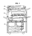
- the image forming apparatus includes an ADF (Automatic Document Feeder) 400.
- a scanner 300 reads a document fed from the ADF 400 while sending image data representative of the document to an image forming section 100.
- a sheet feeding device 200 feeds a sheet or recording medium to the image forming section 100.
- the image forming section 100 forms a toner image on the sheet in accordance with the image data on the sheet. After the toner image has been fixed on the sheet, the sheet or print is driven out of the image forming apparatus.
- the image forming section 100 includes a plurality of photoconductive elements implemented as drums 1 and each being assigned to a particular color. Color-by-color latent images each are formed on one of the drums 1 and then developed by a developing device 2 to become a toner image. The toner images of different colors so formed on the drums 1 are sequentially transferred to an intermediate image transfer body 4 one above the other by primary image transferring devices 3, completing a full-color image.
- the image transfer body 4 is implemented as a belt and will be referred to as a belt 4 hereinafter.
- the full-color image is transferred from the belt 4 to a sheet by a secondary image transferring device 5 and then fixed by a fixing device 7.
- a cleaning device 9 assigned to the belt 4 adjoins one of rollers over which the belt 4 is passed. After the second image transfer, the cleaning device 9 cleans the surface of the belt 4.
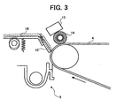
- FIG. 3 shows a specific configuration of the cleaning device 9.
- the cleaning device 9 includes a cleaning blade 10 configured to scrape off tone left on the belt 4 after the secondary image transfer.
- the cleaning blade 10 is formed of fluorocarbon resin, the frictional resistance of the blade 10 decreases. Therefore, even if the surface of the belt 4 is implemented as an elastic layer, the cleaning blade 10 is prevented from being rolled up, rolled in or otherwise deformed by the belt 4 and can desirably clean the belt 4.
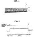
- the belt 4 includes an elastic layer 12, the surface of the elastic layer 12 is coated with fluorocarbon resin to form a surface layer 13.
- the surface layer 13 reduces the frictional resistance of the belt 4 and can therefore be desirably cleaned. It follows that the cleaning blade 10, FIG. 3, is not rolled up, rolled in or otherwise deformed even if it is formed of urethane rubber or similar rubber.
- the surface layer 13 formed of fluorocarbon should preferably be as thin as 2 ⁇ m or less.
- the elastic layer 12 inclusive of the surface layer 13 should preferably be have hardness of 80° or less in JIS (Japanese Industrial Standards) A scale.
- the overall thickness of the belt 4 should preferably be between 0.2 mm and 0.5 mm.
- Fluorocarbon may be polyvinylidene fluoride or tetraethylene fluoride by way of example.
- a coating brush or coating means 14 for coating a lubricant on the belt 4 is positioned downstream of the cleaning device 9 in the direction of movement of the belt 4.
- the coating brush 14 shaves off a solid lubricant 15 little by little and uniformly coats in on the surface of the belt 4.
- the lubricant makes it difficult for toner to remain on the belt 4 and thereby allows the cleaning blade 10 to more easily clean the surface of the belt 4.
- use may be made of zinc stearate or similar common lubricant.
- wax or lubricant powder may be contained in toner in order to promote the parting of toner from the belt. 4. This is also successful to reduce frictional resistance between the cleaning blade 10 and the belt 4.
- the belt 4 can adapt itself to a sheet with an irregular surface more easily as the surface hardness of the elastic layer 12 becomes lower and the elastic layer 12 becomes thicker.
- the cleaning blade 10 leaves a bite mark in the elastic layer 12 when the apparatus is left unused over a long time, resulting in a white horizontal stripe in an image.
- it is likely that the cleaning blade 10 is rolled in when the apparatus starts operating after a long suspension.
- the cleaning device 9 additionally includes a moving mechanism 16 including, e.g., a half-rotation clutch and a cam.
- the moving mechanism 16 brings the cleaning blade 10 into contact with the belt 4 at the beginning of the operation of the apparatus, but releases the former from the latter at the end of the operation.
- FIG. 5 is a timing chart demonstrating a specific operation of the moving mechanism 16. With the moving mechanism 16, it is possible to protect the elastic layer 12 of the belt 4 from a bite mark ascribable to the cleaning blade 10 and to prevent the cleaning blade 10 from being rolled in.
- a cleaning device assigned to an intermediate image transfer body includes a cleaning blade formed of fluorocarbon resin.
- the surface of an intermediate image transfer body including an elastic layer is implemented as a thin coating layer of fluorocarbon resin. Such a configuration allows the intermediate image transfer body to be desirably cleaned.
- a lubricant is coated on the intermediate image transfer body or was or lubricant powder is contained in toner, further promoting the desirable cleaning of the intermediate image transfer body.
- a moving mechanism included in the cleaning device holds the cleaning blade spaced from the intermediate image transfer body at least when image forming is not under way. This protects the intermediate image transfer body from a pressure mark ascribable to the cleaning blade and prevents the cleaning blade from being rolled in.
Landscapes
- Physics & Mathematics (AREA)
- General Physics & Mathematics (AREA)
- Electrostatic Charge, Transfer And Separation In Electrography (AREA)
- Dry Development In Electrophotography (AREA)
- Color Electrophotography (AREA)
- Developing Agents For Electrophotography (AREA)
- Cleaning In Electrography (AREA)
Claims (9)
- Bilderzeugungsvorrichtung, die Folgendes aufweist:einen Zwischenbildübertragungskörper (4), der eine elastische Schicht (12),wenigstens zwei fotoleitfähige Elemente (1), die in Kontakt mit dem Zwischenbildübertragungskörper gehalten werden; undReinigungseinrichtungen (10) zum Reinigen des Zwischenbildübertragungskörpers enthält;wobei eine Beschichtungs- bzw. Überzugschicht auf einer Oberfläche des Zwischenbildübertragungskörpers gebildet ist, und aus einem Material gebildet ist, das nicht elastisch ist und das einen Reibungskoeffizienten aufweist, der kleiner ist als bei einem Material, das die elastische Schicht bildet; wobei die Vorrichtung ferner einen Bewegungsmechanismus (16) zum wahlweisen Bewegen der Reinigungseinrichtungen (10) in oder außer Kontakt mit dem Zwischenbildübertragungskörper aufweist; undwobei der Bewegungsmechanismus die Reinigungseinrichtungen wenigstens von dem Zwischenbildübertragungskörper beabstandet hält, wenn die Vorrichtung außerhalb von Bildererzeugungstätigkeit ist.
- Vorrichtung wie in Anspruch 1 beansprucht, wobei die Beschichtungs- bzw. Überzugschicht eine dünne Oberflächenschicht aufweist, die aus Fluorkohlenstoffharz bzw. flouorhaltigem Kunststoff gebildet ist.
- Vorrichtung wie in Anspruch 2 beansprucht, wobei die Oberflächenschicht 2 µm oder kleiner dick ist, während die elastische Schicht eine Härte von 80 Grad oder weniger in der A-Skala der JIS (Japanische Industrie Standards) hat.
- Vorrichtung wie in Anspruch 3 beansprucht, wobei der Zwischenbildübertragungskörper ein Band aufweist.
- Vorrichtung wie in Anspruch 4 beansprucht, wobei das Band eine Dicke zwischen 0,2 mm und 0,5 mm hat.
- Vorrichtung wie in Anspruch 1 beansprucht, wobei die Reinigungseinrichtung eine Reinigungsklinge aufweist, wobei ein Teil von ihr, der den Zwischenbildübertragungskörper berührt, aus Fluorkohlenstoffharz bzw. fluorhaltigem Kunststoff gebildet ist.
- Vorrichtung wie in Anspruch 1 beansprucht, wobei der Zwischenbildübertragungskörper ein Band aufweist, das bewegbar über eine Mehrzahl von Rollen bzw. Walzen geführt wird.
- Vorrichtung wie in Anspruch 1 beansprucht, die ferner Beschichtungs- bzw. Überzugeinrichtungen zum Auftragen eines Schmiermittels auf den Zwischenbildübertragungskörper aufweisen.
- Vorrichtung wie in Anspruch 1 beansprucht, wobei Toner zum Entwickeln latenter Bilder, die auf den fotoleitfähigen Elementen gebildet sind, eines von Wachs und Schmiermittelpulver enthält.
Applications Claiming Priority (2)
| Application Number | Priority Date | Filing Date | Title |
|---|---|---|---|
| JP2001213178 | 2001-07-13 | ||
| JP2001213178A JP2003029541A (ja) | 2001-07-13 | 2001-07-13 | 画像形成装置 |
Publications (3)
| Publication Number | Publication Date |
|---|---|
| EP1276019A2 EP1276019A2 (de) | 2003-01-15 |
| EP1276019A3 EP1276019A3 (de) | 2003-03-05 |
| EP1276019B1 true EP1276019B1 (de) | 2006-11-15 |
Family
ID=19048209
Family Applications (1)
| Application Number | Title | Priority Date | Filing Date |
|---|---|---|---|
| EP02015545A Expired - Lifetime EP1276019B1 (de) | 2001-07-13 | 2002-07-11 | Bilderzeugungsgerät |
Country Status (4)
| Country | Link |
|---|---|
| US (1) | US6785500B2 (de) |
| EP (1) | EP1276019B1 (de) |
| JP (1) | JP2003029541A (de) |
| DE (1) | DE60216014T2 (de) |
Families Citing this family (50)
| Publication number | Priority date | Publication date | Assignee | Title |
|---|---|---|---|---|
| US7203433B2 (en) * | 2003-06-25 | 2007-04-10 | Ricoh Company, Ltd. | Apparatus for detecting amount of toner deposit and controlling density of image, method of forming misalignment correction pattern, and apparatus for detecting and correcting misalignment of image |
| JP4778671B2 (ja) * | 2003-07-02 | 2011-09-21 | 株式会社リコー | 画像形成装置に用いる転写用部材の抵抗変化判定方法 |
| US7267916B2 (en) * | 2003-07-17 | 2007-09-11 | Ricoh Company, Ltd. | Electrophotographic photoreceptor, and image forming method, image forming apparatus and process cartridge therefor using the electrophotographic photoreceptor |
| JP4194930B2 (ja) * | 2003-12-09 | 2008-12-10 | 株式会社リコー | 画像形成装置、画像形成方法、画像形成装置用プロセスカートリッジ |
| US7212777B2 (en) * | 2004-02-25 | 2007-05-01 | Ricoh Company, Ltd. | Image forming apparatus used in electrostatic process |
| JP2005284219A (ja) * | 2004-03-04 | 2005-10-13 | Ricoh Co Ltd | プロセスカートリッジ及びこれを用いる画像形成装置 |
| JP4294546B2 (ja) | 2004-06-25 | 2009-07-15 | 株式会社リコー | ベルト部材、並びに、これを用いるベルト駆動装置及び画像形成装置 |
| JP2006072008A (ja) * | 2004-09-02 | 2006-03-16 | Ricoh Co Ltd | ベルトユニット及びこれを用いる画像形成装置 |
| US7502583B2 (en) * | 2004-09-10 | 2009-03-10 | Ricoh Company, Limited | Transfer device and image forming apparatus for enhancement of an image stored on a recording medium |
| US7781134B2 (en) * | 2004-12-27 | 2010-08-24 | Ricoh Company, Ltd. | Electrophotographic photoreceptor, image forming method, image forming apparatus and process cartridge for the image forming apparatus |
| US20060199092A1 (en) * | 2005-03-03 | 2006-09-07 | Akihiro Sugino | Electrostatic latent image bearer, and image forming method, image forming apparatus and process cartridge using the electrostatic latent image bearer |
| JP4615340B2 (ja) * | 2005-03-17 | 2011-01-19 | 株式会社リコー | ベルトユニット及びこれが挿脱される画像形成装置 |
| JP2006259430A (ja) * | 2005-03-18 | 2006-09-28 | Ricoh Co Ltd | ベルト装置及び画像形成装置 |
| JP2007003575A (ja) * | 2005-06-21 | 2007-01-11 | Ricoh Co Ltd | 除電装置及びこれを用いた画像形成装置 |
| JP2007127677A (ja) * | 2005-10-31 | 2007-05-24 | Ricoh Co Ltd | ガイド部材および画像形成装置 |
| JP4590344B2 (ja) * | 2005-11-21 | 2010-12-01 | 株式会社リコー | 静電潜像担持体及びそれを用いた画像形成装置、プロセスカートリッジ及び画像形成方法 |
| CN1983063B (zh) * | 2005-12-07 | 2010-12-01 | 株式会社理光 | 能够提供带单元中稳定带移动的成像装置 |
| JP5081428B2 (ja) * | 2005-12-08 | 2012-11-28 | 株式会社リコー | 画像形成装置 |
| JP5032055B2 (ja) | 2006-04-26 | 2012-09-26 | 株式会社リコー | クリーニング装置 |
| JP4724601B2 (ja) * | 2006-05-16 | 2011-07-13 | 株式会社リコー | 画像形成装置および画像形成方法 |
| JP5095133B2 (ja) * | 2006-06-06 | 2012-12-12 | 株式会社リコー | 転写装置の製造方法 |
| JP2007328198A (ja) * | 2006-06-08 | 2007-12-20 | Ricoh Co Ltd | 画像形成装置 |
| US7964327B2 (en) * | 2006-06-13 | 2011-06-21 | Ricoh Company Ltd. | Electrophotographic photoreceptor and method of preparing the photoreceptor, and image forming apparatus, image forming method and process cartridge using the photoreceptor |
| JP4928230B2 (ja) * | 2006-11-10 | 2012-05-09 | 株式会社リコー | 画像形成装置、画像形成方法、及びプロセスカートリッジ |
| JP4917409B2 (ja) * | 2006-11-10 | 2012-04-18 | 株式会社リコー | 画像形成装置、画像形成方法、及びプロセスカートリッジ |
| JP2008139799A (ja) * | 2006-12-05 | 2008-06-19 | Ricoh Co Ltd | 潤滑剤塗布装置、クリーニング装置、画像形成装置及び画像形成方法 |
| JP2008139798A (ja) * | 2006-12-05 | 2008-06-19 | Ricoh Co Ltd | 潤滑剤塗布装置、クリーニング装置、画像形成装置及び画像形成方法 |
| KR101454300B1 (ko) * | 2007-01-04 | 2014-10-27 | 삼성전자주식회사 | 전사벨트 클리닝장치, 이를 구비하는 전사유닛 및화상형성장치 |
| US7715751B2 (en) * | 2007-01-04 | 2010-05-11 | Samsung Electronics Co., Ltd. | Cleaning apparatus, and transfer unit and image forming apparatus including the same |
| KR101090057B1 (ko) * | 2007-02-20 | 2011-12-07 | 삼성전자주식회사 | 화상형성장치 및 그 벨트 클리닝 유닛 |
| JP2008233357A (ja) * | 2007-03-19 | 2008-10-02 | Ricoh Co Ltd | 転写ニップローラ、転写装置及び画像形成装置 |
| JP5142037B2 (ja) * | 2008-07-24 | 2013-02-13 | 株式会社リコー | ベルト部材、転写装置及び画像形成装置 |
| JP5267942B2 (ja) * | 2009-03-17 | 2013-08-21 | 株式会社リコー | 画像形成装置 |
| JP5810684B2 (ja) | 2010-11-04 | 2015-11-11 | 株式会社リコー | 画像形成装置 |
| JP5888588B2 (ja) | 2010-11-19 | 2016-03-22 | 株式会社リコー | 転写装置及び画像形成装置 |
| JP2012194467A (ja) * | 2011-03-17 | 2012-10-11 | Ricoh Co Ltd | 画像形成装置 |
| JP5787207B2 (ja) | 2011-03-18 | 2015-09-30 | 株式会社リコー | 画像形成装置 |
| JP5678841B2 (ja) | 2011-06-02 | 2015-03-04 | 株式会社リコー | 画像形成装置 |
| JP5900056B2 (ja) | 2011-06-08 | 2016-04-06 | 株式会社リコー | 画像形成装置 |
| JP5765073B2 (ja) | 2011-06-16 | 2015-08-19 | 株式会社リコー | 画像形成装置 |
| JP5830956B2 (ja) | 2011-06-21 | 2015-12-09 | 株式会社リコー | 画像形成装置 |
| JP5696678B2 (ja) | 2011-06-28 | 2015-04-08 | 株式会社リコー | 画像形成装置 |
| JP5891628B2 (ja) | 2011-07-15 | 2016-03-23 | 株式会社リコー | 画像形成装置 |
| JP5729227B2 (ja) | 2011-09-13 | 2015-06-03 | 株式会社リコー | 画像形成装置 |
| JP6065406B2 (ja) | 2011-10-11 | 2017-01-25 | 株式会社リコー | 転写装置及び画像形成装置 |
| JP5998710B2 (ja) | 2011-11-30 | 2016-09-28 | 株式会社リコー | 画像形成装置 |
| JP6083199B2 (ja) | 2012-01-11 | 2017-02-22 | 株式会社リコー | 画像形成装置 |
| JP6478021B2 (ja) | 2014-02-12 | 2019-03-06 | 株式会社リコー | 光導電体とそれを用いた画像形成方法および画像形成装置 |
| US10416594B2 (en) | 2016-10-21 | 2019-09-17 | Ricoh Company, Ltd. | Image forming method, image forming apparatus, and process cartridge |
| JP6821425B2 (ja) * | 2016-12-26 | 2021-01-27 | キヤノン株式会社 | 画像形成装置 |
Family Cites Families (25)
| Publication number | Priority date | Publication date | Assignee | Title |
|---|---|---|---|---|
| JPH01140174A (ja) * | 1987-11-27 | 1989-06-01 | Mitsubishi Petrochem Co Ltd | 電子写真装置用ブレード |
| JP3200179B2 (ja) | 1991-10-24 | 2001-08-20 | 株式会社リコー | 画像形成装置の転写装置 |
| JP3373651B2 (ja) * | 1994-06-02 | 2003-02-04 | 株式会社リコー | 画像形成装置 |
| JP3516551B2 (ja) | 1995-05-11 | 2004-04-05 | 株式会社リコー | 静電画像形成装置 |
| US5870650A (en) | 1996-07-18 | 1999-02-09 | Ricoh Company, Ltd. | Image forming apparatus having a device to apply a release agent to a surface of a transfer roller |
| JPH1031374A (ja) * | 1996-07-18 | 1998-02-03 | Fuji Xerox Co Ltd | 画像形成装置 |
| US5978639A (en) * | 1997-05-02 | 1999-11-02 | Bridgestone Corporation | Intermediate transfer member and intermediate transfer device |
| JP3792902B2 (ja) * | 1997-08-04 | 2006-07-05 | キヤノン株式会社 | 画像形成装置 |
| JPH11149177A (ja) * | 1997-11-17 | 1999-06-02 | Canon Inc | 画像形成方法 |
| GB2336442B (en) * | 1998-04-17 | 2000-09-06 | Ricoh Kk | Multi-color toner set and method of forming multi-color images, using the multi-color toner set |
| JP2000010416A (ja) | 1998-06-19 | 2000-01-14 | Canon Inc | 画像形成装置 |
| JP3486556B2 (ja) | 1998-06-22 | 2004-01-13 | キヤノン株式会社 | 乾式トナー及び画像形成方法 |
| JP4196134B2 (ja) * | 1998-06-26 | 2008-12-17 | 株式会社ブリヂストン | 中間転写部材及び画像形成装置 |
| JP2000131920A (ja) * | 1998-10-23 | 2000-05-12 | Canon Inc | 画像形成装置 |
| JP3846072B2 (ja) * | 1998-11-12 | 2006-11-15 | 富士ゼロックス株式会社 | 中間転写体およびこれを用いた画像形成装置 |
| JP3676932B2 (ja) | 1998-11-24 | 2005-07-27 | 株式会社リコー | 転写方法及び画像形成装置 |
| CN1123805C (zh) * | 1998-11-24 | 2003-10-08 | 株式会社理光 | 图像形成装置中的消电技术及清洁技术的改良 |
| JP2000155511A (ja) | 1998-11-24 | 2000-06-06 | Ricoh Co Ltd | 画像形成装置、画像形成方法、中間転写装置、及び、転写方法 |
| JP3780110B2 (ja) * | 1998-12-07 | 2006-05-31 | 株式会社リコー | 当接装置及び画像形成装置 |
| JP4175714B2 (ja) * | 1999-02-12 | 2008-11-05 | 株式会社リコー | 中間転写体及び画像形成装置 |
| JP2000310912A (ja) | 1999-02-23 | 2000-11-07 | Ricoh Co Ltd | 画像形成装置 |
| JP2001042666A (ja) * | 1999-05-26 | 2001-02-16 | Ricoh Co Ltd | 画像形成装置 |
| JP2001166659A (ja) * | 1999-12-07 | 2001-06-22 | Fuji Xerox Co Ltd | 画像形成装置 |
| JP2001201994A (ja) | 2000-01-19 | 2001-07-27 | Ricoh Co Ltd | 画像形成装置 |
| JP3975049B2 (ja) | 2000-07-10 | 2007-09-12 | 株式会社リコー | 転写装置及び画像形成装置 |
-
2001
- 2001-07-13 JP JP2001213178A patent/JP2003029541A/ja active Pending
-
2002
- 2002-07-11 DE DE60216014T patent/DE60216014T2/de not_active Expired - Lifetime
- 2002-07-11 EP EP02015545A patent/EP1276019B1/de not_active Expired - Lifetime
- 2002-07-12 US US10/193,219 patent/US6785500B2/en not_active Expired - Lifetime
Also Published As
| Publication number | Publication date |
|---|---|
| EP1276019A3 (de) | 2003-03-05 |
| DE60216014D1 (de) | 2006-12-28 |
| JP2003029541A (ja) | 2003-01-31 |
| EP1276019A2 (de) | 2003-01-15 |
| US20030016968A1 (en) | 2003-01-23 |
| US6785500B2 (en) | 2004-08-31 |
| DE60216014T2 (de) | 2007-07-05 |
Similar Documents
| Publication | Publication Date | Title |
|---|---|---|
| EP1276019B1 (de) | Bilderzeugungsgerät | |
| US6983121B2 (en) | Image forming apparatus, image transferring device and recording medium conveying method | |
| CN100358727C (zh) | 成像设备 | |
| US7277657B2 (en) | Cleaning device and image forming apparatus including the cleaning device that controls occurrences of background fouling and abnormal image | |
| US20110255909A1 (en) | Image forming apparatus | |
| US7620340B2 (en) | Image forming apparatus with cleaning blade lubrication | |
| US7440720B2 (en) | Image forming apparatus and image transferring unit for the same | |
| JP2000172082A (ja) | 画像形成装置 | |
| JP2004272118A (ja) | 画像形成装置 | |
| JP5487866B2 (ja) | クリーニング装置 | |
| JPH03288173A (ja) | 画像形成装置 | |
| JP2002226070A (ja) | 給紙装置及びそれを使用した画像形成装置 | |
| JP5540719B2 (ja) | 画像形成装置 | |
| JP4920936B2 (ja) | 画像形成装置 | |
| JP2003058006A (ja) | 清掃装置 | |
| JP3756090B2 (ja) | 画像形成装置 | |
| JP3712034B2 (ja) | 画像形成装置 | |
| JP2005107053A (ja) | カラ−画像形成装置 | |
| JP6277978B2 (ja) | 像担持体、及びこれを備えた画像形成装置 | |
| JP2007121965A (ja) | 画像形成装置 | |
| US20030049055A1 (en) | Developing apparatus and image forming apparatus for stably forming a developer layer on a developer device | |
| JP2002341671A (ja) | 転写搬送装置 | |
| JP2005099732A (ja) | 画像形成装置 | |
| JP2000172093A (ja) | 画像形成装置 | |
| JP2003195658A (ja) | 画像形成装置 |
Legal Events
| Date | Code | Title | Description |
|---|---|---|---|
| PUAI | Public reference made under article 153(3) epc to a published international application that has entered the european phase |
Free format text: ORIGINAL CODE: 0009012 |
|
| 17P | Request for examination filed |
Effective date: 20020711 |
|
| AK | Designated contracting states |
Kind code of ref document: A2 Designated state(s): AT BE BG CH CY CZ DE DK EE ES FI FR GB GR IE IT LI LU MC NL PT SE SK TR |
|
| AX | Request for extension of the european patent |
Free format text: AL;LT;LV;MK;RO;SI |
|
| PUAL | Search report despatched |
Free format text: ORIGINAL CODE: 0009013 |
|
| AK | Designated contracting states |
Kind code of ref document: A3 Designated state(s): AT BE BG CH CY CZ DE DK EE ES FI FR GB GR IE IT LI LU MC NL PT SE SK TR |
|
| AX | Request for extension of the european patent |
Extension state: AL LT LV MK RO SI |
|
| AKX | Designation fees paid |
Designated state(s): DE FR GB |
|
| 17Q | First examination report despatched |
Effective date: 20040719 |
|
| GRAP | Despatch of communication of intention to grant a patent |
Free format text: ORIGINAL CODE: EPIDOSNIGR1 |
|
| GRAS | Grant fee paid |
Free format text: ORIGINAL CODE: EPIDOSNIGR3 |
|
| GRAA | (expected) grant |
Free format text: ORIGINAL CODE: 0009210 |
|
| AK | Designated contracting states |
Kind code of ref document: B1 Designated state(s): DE FR GB |
|
| REG | Reference to a national code |
Ref country code: GB Ref legal event code: FG4D |
|
| REF | Corresponds to: |
Ref document number: 60216014 Country of ref document: DE Date of ref document: 20061228 Kind code of ref document: P |
|
| ET | Fr: translation filed | ||
| PLBE | No opposition filed within time limit |
Free format text: ORIGINAL CODE: 0009261 |
|
| STAA | Information on the status of an ep patent application or granted ep patent |
Free format text: STATUS: NO OPPOSITION FILED WITHIN TIME LIMIT |
|
| 26N | No opposition filed |
Effective date: 20070817 |
|
| REG | Reference to a national code |
Ref country code: FR Ref legal event code: PLFP Year of fee payment: 15 |
|
| REG | Reference to a national code |
Ref country code: FR Ref legal event code: PLFP Year of fee payment: 16 |
|
| PGFP | Annual fee paid to national office [announced via postgrant information from national office to epo] |
Ref country code: DE Payment date: 20170724 Year of fee payment: 16 Ref country code: GB Payment date: 20170719 Year of fee payment: 16 Ref country code: FR Payment date: 20170724 Year of fee payment: 16 |
|
| REG | Reference to a national code |
Ref country code: DE Ref legal event code: R119 Ref document number: 60216014 Country of ref document: DE |
|
| GBPC | Gb: european patent ceased through non-payment of renewal fee |
Effective date: 20180711 |
|
| PG25 | Lapsed in a contracting state [announced via postgrant information from national office to epo] |
Ref country code: FR Free format text: LAPSE BECAUSE OF NON-PAYMENT OF DUE FEES Effective date: 20180731 Ref country code: DE Free format text: LAPSE BECAUSE OF NON-PAYMENT OF DUE FEES Effective date: 20190201 Ref country code: GB Free format text: LAPSE BECAUSE OF NON-PAYMENT OF DUE FEES Effective date: 20180711 |