EP1276249A1 - Dispositif pour améliorer les caractéristiques de transmission d'un faisceau de lignes de données et système de transmission de données - Google Patents
Dispositif pour améliorer les caractéristiques de transmission d'un faisceau de lignes de données et système de transmission de données Download PDFInfo
- Publication number
- EP1276249A1 EP1276249A1 EP01116651A EP01116651A EP1276249A1 EP 1276249 A1 EP1276249 A1 EP 1276249A1 EP 01116651 A EP01116651 A EP 01116651A EP 01116651 A EP01116651 A EP 01116651A EP 1276249 A1 EP1276249 A1 EP 1276249A1
- Authority
- EP
- European Patent Office
- Prior art keywords
- signal
- bundle
- signals
- tapped
- data line
- Prior art date
- Legal status (The legal status is an assumption and is not a legal conclusion. Google has not performed a legal analysis and makes no representation as to the accuracy of the status listed.)
- Withdrawn
Links
- 230000005540 biological transmission Effects 0.000 title claims abstract description 41
- 230000003044 adaptive effect Effects 0.000 claims abstract description 37
- 238000012937 correction Methods 0.000 claims abstract description 6
- 238000000034 method Methods 0.000 claims description 9
- RYGMFSIKBFXOCR-UHFFFAOYSA-N Copper Chemical compound [Cu] RYGMFSIKBFXOCR-UHFFFAOYSA-N 0.000 claims description 4
- 229910052802 copper Inorganic materials 0.000 claims description 4
- 239000010949 copper Substances 0.000 claims description 4
- 238000010079 rubber tapping Methods 0.000 claims description 2
- 230000006978 adaptation Effects 0.000 description 3
- 230000000875 corresponding effect Effects 0.000 description 2
- 230000001419 dependent effect Effects 0.000 description 2
- 238000005516 engineering process Methods 0.000 description 2
- 230000001360 synchronised effect Effects 0.000 description 2
- 238000012549 training Methods 0.000 description 2
- 101150012579 ADSL gene Proteins 0.000 description 1
- 102100020775 Adenylosuccinate lyase Human genes 0.000 description 1
- 108700040193 Adenylosuccinate lyases Proteins 0.000 description 1
- 238000004891 communication Methods 0.000 description 1
- 230000002596 correlated effect Effects 0.000 description 1
- 238000013461 design Methods 0.000 description 1
- 238000011161 development Methods 0.000 description 1
- 230000018109 developmental process Effects 0.000 description 1
- 230000000694 effects Effects 0.000 description 1
- 230000002452 interceptive effect Effects 0.000 description 1
- 239000011159 matrix material Substances 0.000 description 1
- 238000012986 modification Methods 0.000 description 1
- 230000004048 modification Effects 0.000 description 1
- 238000012545 processing Methods 0.000 description 1
- 230000003595 spectral effect Effects 0.000 description 1
- 230000001629 suppression Effects 0.000 description 1
Images


Classifications
-
- H—ELECTRICITY
- H04—ELECTRIC COMMUNICATION TECHNIQUE
- H04L—TRANSMISSION OF DIGITAL INFORMATION, e.g. TELEGRAPHIC COMMUNICATION
- H04L12/00—Data switching networks
- H04L12/02—Details
- H04L12/16—Arrangements for providing special services to substations
-
- H—ELECTRICITY
- H04—ELECTRIC COMMUNICATION TECHNIQUE
- H04B—TRANSMISSION
- H04B3/00—Line transmission systems
- H04B3/02—Details
- H04B3/32—Reducing cross-talk, e.g. by compensating
Definitions
- the invention relates to a device for improvement the transmission properties of a bundle of electrical Data lines according to claim 1 and an arrangement for Data transmission according to claim 11.
- the influence of the disturbances can be kept low, by the devices connected to the cable bundle be coordinated, in particular synchronized become.
- this is complex and leads to Restrictions on the modems used and Transmission technologies.
- the invention has for its object a device to specify with which the transmission properties of a Bundle of electrical data lines is improved, so regardless of the on the data lines connected devices interference suppression of the lines among themselves and thus an increase in Transmission capacity is made possible.
- the device comprises at least one adaptive filter with which one on a first line transmitted signal is suppressed.
- the device By placing the device within the transmission link, e.g. on one or both ends of the cable bundle is arranged, the Transmission properties of the cable bundle itself improved. Knowledge of the transmission techniques used or the connected devices are not necessary.
- the device is completely transparent and regardless of the structure of the connected devices. The participants therefore have no restrictions regarding of the devices and transmission technologies used be imposed in order to achieve a high transmission capacity or maintain quality.
- Adaptive filter to reduce or compensate for a Disruption of unknown nature on a signal line is on known. They are, for example, in B. Widrow and S. Stearns, Adaptive Signal Processing, Prentice-Hall, Inc., New Jersey, 1985.
- One on one Signal line transmitted useful signal to be suppressed is composed of the undisturbed signal and the Interference from the unknown signal source.
- One with this Signal source correlated signal is used as a reference signal fed to an adaptive filter.
- the filter creates a Compensation signal that is subtracted from the useful signal.
- the compensated useful signal thus obtained is the filter supplied as an error signal.
- the filter parameters are like this set that the performance of the compensated Useful signal is minimized, which ideally the corresponds to undisturbed signal.
- the invention can take a variety of forms can be realized, some of which are in the drawings are shown.
- Everyone is to be suppressed assigned at least one adaptive filter. This creates a compensation signal which of the on the line transmitted useful signal is subtracted.
- Reference signal for the adaptive filter serves at least a signal tapped from another line, see above that the interference, e.g. NEXT and / or FEXT on this line transmitted signals is reduced.
- the interference e.g. NEXT and / or FEXT on this line transmitted signals is reduced.
- this variant of the invention is for one each decoupling pair of lines an adaptive filter intended. It is also possible to use the reference signals only of the lines on which transmission is carried out tap off.
- this will be Reference signal from an unwired line tapped.
- This signal is an illustration of all Interference from neighboring lines on which are sent or is received.
- the tapped signal is therefore in also the corresponding interference influences on the line to be suppressed again.
- it be according to the invention used as a reference signal for an adaptive filter, a quick adaptation of the filter and thus one succeeds quick compensation.
- a Tapped off reference signal outside the cable bundle for example on an external antenna. In this way can also cause external interference to some or all of them Data lines are compensated.
- connection lines preferably two connections available, the one for example to connect the cable bundle to be suppressed and the other one for connection one leading to one or more participants Cable bundle or for the direct connection of end devices, e.g. xDSL devices.
- the device comprises the another bundle connecting the connections device-internal connecting lines, these Connection lines at least one connection point have which reference and / or error signals tapped and / or correction signals are supplied can. There is therefore no need for the external cable itself Modifications are made.
- the device comprises the further hybrid circuits with which the transmit and Receive signals that are common to each connected wire pair of the cable bundle, separately and each with its own internal Connection line can be assigned. On this Connection lines can then the appropriate place Reference and error signals for setting the adaptive Filters are tapped and the generated ones Correction signals are supplied. If the adaptive filter, e.g. in the event of a power failure, the Data flow not interrupted.
- Every data line is used for the best possible compensation decoupled from any other data line, for example, for each additional data line adaptive filter is provided or by the others
- Data lines tapped signals a common adaptive filter can be supplied as a reference signal.
- There crosstalk is highly dependent on the distance, it can sufficient for many applications, only those immediately to suppress adjacent data lines from each other.
- Telecommunication cables often have two pairs of Copper twisted pair twisted together.
- Star quads are in a common basic bundle contain. Again, several such basic bundles form that Telecommunication cables. In such a case, be preferred at least the data lines of a star quad and particularly preferably also that of a basic bundle against one another suppressed.
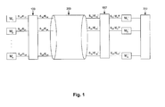
- FIG. 1 shows an arrangement according to the invention for data transmission in the application case with a central switching device 300 and a plurality of terminals M 1 , M 2 ... M n and M 1 ', M 2 ', ... M n ', which are preferably xDSL Modems are.
- the terminals M 1 and M 1 ', M 2 and M 2 ' ... M n and M n ' represent 1 ... n any xDSL connections. They are each via a pair of wires S 1 / E 1 , S 2 / E 2 ...
- the reference symbols S iT , S iK , S ' iT , S' iK , E iT , E iK , E ' iT , E' iK each denote the subscriber or cable-side section the send or receive path on the two cable sides.
- the wire pairs are combined into a bundle 200 of lines and are located in the immediate vicinity of this cable in the area of this cable.
- one, if necessary two, devices 100 and 100 'according to the invention are located in the transmission path between the modems and the wire pairs of the cable.
- the individual wire pairs of the cable bundle 200 are connected to the terminals M 1 ', M 2 ' ... M n 'at their end on the exchange side. At their subscriber end, individual wire pairs are connected to the terminals M 1 , M 2 ... M n .
- These wire pairs can also be combined to form a further basic bundle.
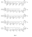
- FIG. 2 shows a first example of a circuit arrangement that can be used in a device according to the invention.
- a plurality of wire pairs, S 1 / E 1 , S 2 / E 2 ... S n / E n which are connected to both the send and the receive signal of the associated modem pair M 1 - M 1 ', M 2 - M 2 '... M n - M n ' are interconnected, are suppressed against each other and against an external source of interference.
- each wire pair of the cable bundle which contributes to interference in the other wire pairs, is inserted into the transmission lines S.
- G K1 , G K2 ... G Kn on the cable side or G T1 , G T2 ...
- each receive line E 1 , E 2 ... E n n are assigned adaptive filters A, where n indicates the number of wire pairs present.
- the adaptive filters receive as a reference signal the signal tapped at the cable-side fork point 1, 2 ... n of an adjacent pair of wires. This is made up of the signal sent and received on this wire pair and the interference signals from the neighboring wire pairs.
- An adaptive filter is thus assigned to two wire pairs in order to suppress the signal transmitted on the first reception line, for example E 1 , against the signal transmitted on a further wire pair, for example S 2 / E 2 .
- Another adaptive filter A x is provided to compensate for an external interference.
- the circuit arrangement according to the invention comprises a matrix of nxn adaptive filters with which all interference influences are mutually compensated. By tapping the reference signal at the fork point of adjacent wires, both the near and the far crosstalk are compensated.
- FIG. 3 shows a further circuit arrangement in which, for example, in order to suppress a received signal on the wire pair S 1 / E 1, two reference points 2a, 2b; ... na, nb and the corresponding number of adaptive filters are used.
- the transmit and receive signals are used separately as reference signals.
- an adaptive filter is also provided for the own pair of wires, which taps as a reference signal the signal sent by the own modem as reference point 1 and thus effects an echo cancellation.
- a further adaptive filter is provided for the compensation of external disturbances.
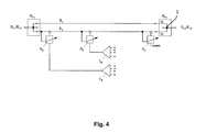
- FIG. 4 shows a further example of a circuit arrangement according to the invention, only one pair of wires and the associated adaptive filters being shown.
- three adaptive filters A S , A E , A X are assigned to each pair of wires.
- a filter A S receives as a reference signal the sum of all transmission signals of all or only the remaining wire pairs summed up in a summing element ⁇ s .
- the second filter A E receives as
- Reference signal is the sum total of all received signals of the other wire pairs in a summing element ⁇ E.
- a filter A X is used to compensate for external interference.
- the reference points 1a, 1b ... na, nb correspond to those from FIG. 3. This arrangement can be implemented simply and inexpensively, since the number of adaptive filters is reduced compared to the examples according to FIGS. 2 and 3.
- FIG. 5 A further simplification is shown in FIG. 5.
- a filter A X again serves to compensate for external disturbances.
- a further simplification results from the fact that the supplier uses an unconnected wire pair for the reference signals. With a suitable position within the cable, all disturbing signals are naturally present on it.
- the summing element can thus be omitted and replaced by an operational amplifier to which the pair of reference wires is connected and which decouples the summing element and makes it available to each transversal filter.
- a filter A X again serves to compensate for external disturbances.
Landscapes
- Engineering & Computer Science (AREA)
- Computer Networks & Wireless Communication (AREA)
- Signal Processing (AREA)
- Cable Transmission Systems, Equalization Of Radio And Reduction Of Echo (AREA)
- Communication Control (AREA)
- Communication Cables (AREA)
Priority Applications (18)
| Application Number | Priority Date | Filing Date | Title |
|---|---|---|---|
| EP01116651A EP1276249A1 (fr) | 2001-07-13 | 2001-07-13 | Dispositif pour améliorer les caractéristiques de transmission d'un faisceau de lignes de données et système de transmission de données |
| AU2002321214A AU2002321214B2 (en) | 2001-07-13 | 2002-07-15 | Device for improving the transmission properties of a bundle of electrical data lines and a system for transmitting data |
| MXPA04000250A MXPA04000250A (es) | 2001-07-13 | 2002-07-15 | Aparato para mejorar las caracteristicas de transmision de un paquete de lineas electricas de datos, y un ordenamiento para la transmision de datos. |
| BR0211136-5A BR0211136A (pt) | 2001-07-13 | 2002-07-15 | Dispositivo para o aperfeiçoamento das propriedades de transmissão de um feixe de linhas elétricas de dados e disposição para a transmissão de dados |
| US10/483,685 US7656955B2 (en) | 2001-07-13 | 2002-07-15 | Device for improving the transmission properties of a bundle of electrical data lines and a system for transmitting data |
| CA2452864A CA2452864C (fr) | 2001-07-13 | 2002-07-15 | Dispositif permettant d'ameliorer les proprietes de transmission d'un faisceau de lignes de donnees electriques, et systeme de transmission des donnees |
| AT02754878T ATE422735T1 (de) | 2001-07-13 | 2002-07-15 | Vorrichtung zur verbesserung der übertragungseigenschaften eines bündels elektrischer datenleitungen und anordnung zur datenübertragung |
| CN028180380A CN1555609B (zh) | 2001-07-13 | 2002-07-15 | 改善电数据线束传输特性的装置和数据传输系统 |
| ES02754878T ES2321169T3 (es) | 2001-07-13 | 2002-07-15 | Dispositivo para la mejora de las propiedades de transmision de un haz de conducciones electricas de datos y disposicion para la transmision de datos. |
| IL15985102A IL159851A0 (en) | 2001-07-13 | 2002-07-15 | Device for improving the transmission properties of a bundle of electrical data lines and a system for transmitting data |
| KR1020047000559A KR100895735B1 (ko) | 2001-07-13 | 2002-07-15 | 일단의 전기적 데이터 라인의 전송 특성 개선 장치, 및데이터 전송 장치 |
| EP02754878A EP1415409B1 (fr) | 2001-07-13 | 2002-07-15 | Dispositif pour ameliorer les proprietes de transmission d'un faisceau de lignes de donnees electriques et systeme de transmission de donnees |
| PCT/EP2002/007783 WO2003009490A2 (fr) | 2001-07-13 | 2002-07-15 | Dispositif pour ameliorer les proprietes de transmission d'un faisceau de lignes de donnees electriques et systeme de transmission de donnees |
| DE50213275T DE50213275D1 (de) | 2001-07-13 | 2002-07-15 | Vorrichtung zur verbesserung der übertragungseigenschaften eines bündels elektrischer datenleitungen und anordnung zur datenübertragung |
| JP2003514714A JP4652683B2 (ja) | 2001-07-13 | 2002-07-15 | 電気データ回線束の伝送特性向上のための装置およびデータ伝送配列 |
| RU2004104344/09A RU2313179C2 (ru) | 2001-07-13 | 2002-07-15 | Устройство для повышения пропускной способности группы электрических линий передачи данных и система для передачи данных |
| PL367691A PL205135B1 (pl) | 2001-07-13 | 2002-07-15 | Urządzenie do ulepszania właściwości transmisyjnych wiązki kablowej linii danych oraz system transmisji danych |
| IL159851A IL159851A (en) | 2001-07-13 | 2004-01-13 | Device for improving the transmission characteristics of electrical information lines and an information transmission system |
Applications Claiming Priority (1)
| Application Number | Priority Date | Filing Date | Title |
|---|---|---|---|
| EP01116651A EP1276249A1 (fr) | 2001-07-13 | 2001-07-13 | Dispositif pour améliorer les caractéristiques de transmission d'un faisceau de lignes de données et système de transmission de données |
Publications (1)
| Publication Number | Publication Date |
|---|---|
| EP1276249A1 true EP1276249A1 (fr) | 2003-01-15 |
Family
ID=8177990
Family Applications (2)
| Application Number | Title | Priority Date | Filing Date |
|---|---|---|---|
| EP01116651A Withdrawn EP1276249A1 (fr) | 2001-07-13 | 2001-07-13 | Dispositif pour améliorer les caractéristiques de transmission d'un faisceau de lignes de données et système de transmission de données |
| EP02754878A Expired - Lifetime EP1415409B1 (fr) | 2001-07-13 | 2002-07-15 | Dispositif pour ameliorer les proprietes de transmission d'un faisceau de lignes de donnees electriques et systeme de transmission de donnees |
Family Applications After (1)
| Application Number | Title | Priority Date | Filing Date |
|---|---|---|---|
| EP02754878A Expired - Lifetime EP1415409B1 (fr) | 2001-07-13 | 2002-07-15 | Dispositif pour ameliorer les proprietes de transmission d'un faisceau de lignes de donnees electriques et systeme de transmission de donnees |
Country Status (16)
| Country | Link |
|---|---|
| US (1) | US7656955B2 (fr) |
| EP (2) | EP1276249A1 (fr) |
| JP (1) | JP4652683B2 (fr) |
| KR (1) | KR100895735B1 (fr) |
| CN (1) | CN1555609B (fr) |
| AT (1) | ATE422735T1 (fr) |
| AU (1) | AU2002321214B2 (fr) |
| BR (1) | BR0211136A (fr) |
| CA (1) | CA2452864C (fr) |
| DE (1) | DE50213275D1 (fr) |
| ES (1) | ES2321169T3 (fr) |
| IL (2) | IL159851A0 (fr) |
| MX (1) | MXPA04000250A (fr) |
| PL (1) | PL205135B1 (fr) |
| RU (1) | RU2313179C2 (fr) |
| WO (1) | WO2003009490A2 (fr) |
Families Citing this family (13)
| Publication number | Priority date | Publication date | Assignee | Title |
|---|---|---|---|---|
| DE10046901A1 (de) * | 2000-09-21 | 2002-05-02 | Siemens Ag | Verfahren und Vorrichtung zur Verbesserung der Übertragungsqualität in einem paket-orientierten Datenübertragungsnetz |
| JP4869853B2 (ja) * | 2006-10-02 | 2012-02-08 | 日本電気株式会社 | 送信出力制御装置、マルチキャリア伝送システム、送信出力制御方法及び送信出力制御プログラム |
| DE102007018585B4 (de) | 2007-04-18 | 2009-02-26 | Broadband United Gmbh | Vorrichtung und Verfahren zur Ermittlung und Kompensation von Störsignalen in einem Nachrichtenübertragungssystem |
| EP2169931B1 (fr) * | 2008-09-24 | 2017-08-09 | ADTRAN GmbH | Procédé et dispositif de traitement de données et système de communication comprenant un tel dispositif |
| AU2008363468B2 (en) | 2008-10-28 | 2011-08-25 | Fujitsu Limited | Wireless base station device using cooperative HARQ communication method, wireless terminal device, wireless communication system, and wireless communication method |
| US8432955B2 (en) | 2009-07-10 | 2013-04-30 | Futurewei Technologies, Inc. | Method for robust crosstalk precoder training in channels with impulse noise |
| RU2419969C2 (ru) * | 2009-07-15 | 2011-05-27 | Государственное образовательное учреждение высшего профессионального образования "Якутский государственный университет имени М.К. Аммосова" (ГОУ ЯГУ) | Способ снижения перекрестных помех в четырехпроводных электрических линиях передачи данных |
| RU2585659C2 (ru) * | 2011-01-14 | 2016-06-10 | Телефонактиеболагет Л М Эрикссон (Пабл) | Ограничение перекрестных помех между модемами |
| JP5664295B2 (ja) * | 2011-02-03 | 2015-02-04 | 富士通株式会社 | 通信装置および通信装置設定方法 |
| EP3035550B1 (fr) | 2013-09-18 | 2017-11-08 | Huawei Technologies Co., Ltd. | Procédé et système de désactivation dans un scénario de diaphonie |
| RU2579915C2 (ru) * | 2014-04-25 | 2016-04-10 | Вячеслав Николаевич Федоров | Способ подавления перекрестных помех в многопроводных линиях связи |
| CN105896197A (zh) * | 2016-05-26 | 2016-08-24 | 江苏省东方世纪网络信息有限公司 | 数据电缆连接器 |
| CN112332881B (zh) * | 2020-10-19 | 2022-04-26 | 深圳市信锐网科技术有限公司 | 使能电路及通信装置 |
Citations (4)
| Publication number | Priority date | Publication date | Assignee | Title |
|---|---|---|---|---|
| US5271037A (en) * | 1990-10-10 | 1993-12-14 | Alcatel N.V. | Line equipment for the compensation of crosstalk |
| WO1997040587A1 (fr) * | 1996-04-19 | 1997-10-30 | Amati Communications Corporation | Annulation du bruit sur des frequences radio |
| US5887032A (en) * | 1996-09-03 | 1999-03-23 | Amati Communications Corp. | Method and apparatus for crosstalk cancellation |
| US5970088A (en) * | 1996-05-09 | 1999-10-19 | Texas Instruments Incorporated | Reverse channel next cancellation for MDSL modem pool |
Family Cites Families (21)
| Publication number | Priority date | Publication date | Assignee | Title |
|---|---|---|---|---|
| SU1037428A1 (ru) * | 1981-04-28 | 1983-08-23 | Военная Инженерная Радиотехническая Ордена Октябрьской Революции И Ордена Отечественной Войны Академия Противовоздушной Обороны Им.Маршала Советского Союза Говорова Л.А. | Устройство дл подавлени помех в двухпроводных лини х св зи |
| LU85402A1 (de) * | 1983-12-01 | 1984-09-11 | Siemens Ag | Verfahren und schaltungsanordnung zur kompensation von uebersprech-u./o.echosignalen |
| SU1307595A1 (ru) * | 1985-12-02 | 1987-04-30 | Ленинградский Электротехнический Институт Связи Им.Проф.М.А.Бонч-Бруевича | Устройство дл компенсации внешних помех кабельных магистралей |
| BE1005305A3 (nl) * | 1991-09-04 | 1993-06-22 | Zuivere Interkommunale Voor Te | Werkwijze voor het in een van ten minste een aftakdoos voorzien kabelnet aanbrengen van een bijkomende module en daarbij te gebruiken module. |
| KR0150757B1 (ko) * | 1995-12-20 | 1998-11-02 | 양승택 | 전송매체특성에 따른 선로구동 시스템 |
| US6014412A (en) * | 1996-04-19 | 2000-01-11 | Amati Communications Corporation | Digital radio frequency interference canceller |
| US6055268A (en) * | 1996-05-09 | 2000-04-25 | Texas Instruments Incorporated | Multimode digital modem |
| US5953412A (en) * | 1996-09-04 | 1999-09-14 | Teltrend, Inc. | Method and apparatus for controlling line conditioner equalizer |
| US6160790A (en) * | 1996-12-31 | 2000-12-12 | Paradyne Corporation | Crosstalk canceller system and method |
| US6014371A (en) * | 1997-03-05 | 2000-01-11 | Paradyne Corporation | Echo cancellation system and method for multipoint networks |
| US6052420A (en) * | 1997-05-15 | 2000-04-18 | Northern Telecom Limited | Adaptive multiple sub-band common-mode RFI suppression |
| CA2649659A1 (fr) * | 1998-03-09 | 1999-09-16 | Broadcom Corporation | Transmetteur ethernet de gigabits |
| TW440767B (en) * | 1998-06-02 | 2001-06-16 | Fujitsu Ltd | Method of and apparatus for correctly transmitting signals at high speed without waveform distortion |
| KR100468830B1 (ko) * | 1998-06-18 | 2005-05-17 | 삼성전자주식회사 | 초고속디지탈가입자선시스템에서협대역잡음제거기능을갖는수신장치및협대역잡음제거방법 |
| KR100309101B1 (ko) * | 1998-08-26 | 2001-11-17 | 윤종용 | 하이브리드 밸런스 및 특성 임피던스를 최적화시키기 위한장치 및 방법 |
| KR20010019438A (ko) * | 1999-08-27 | 2001-03-15 | 윤종용 | 특성 가변 아날로그 필터를 이용한 적응형 반향 제거장치 |
| US6965657B1 (en) * | 1999-12-01 | 2005-11-15 | Velocity Communication, Inc. | Method and apparatus for interference cancellation in shared communication mediums |
| EP1109328B1 (fr) * | 1999-12-14 | 2004-02-25 | STMicroelectronics S.A. | Systéme de transmission DSL avec compensation de télédiaphonie |
| EP1109329B1 (fr) * | 1999-12-14 | 2003-04-02 | STMicroelectronics S.A. | Système de transmission DSL avec compensation de la télédiaphonie |
| US20020093908A1 (en) * | 2000-11-24 | 2002-07-18 | Esion Networks Inc. | Noise/interference suppression system |
| US6831900B2 (en) * | 2001-02-09 | 2004-12-14 | Agere Systems Inc. | Filter cell, method of deriving an echo component and an echo canceling system employing the same |
-
2001
- 2001-07-13 EP EP01116651A patent/EP1276249A1/fr not_active Withdrawn
-
2002
- 2002-07-15 KR KR1020047000559A patent/KR100895735B1/ko not_active Expired - Fee Related
- 2002-07-15 US US10/483,685 patent/US7656955B2/en not_active Expired - Fee Related
- 2002-07-15 AT AT02754878T patent/ATE422735T1/de not_active IP Right Cessation
- 2002-07-15 MX MXPA04000250A patent/MXPA04000250A/es active IP Right Grant
- 2002-07-15 EP EP02754878A patent/EP1415409B1/fr not_active Expired - Lifetime
- 2002-07-15 CN CN028180380A patent/CN1555609B/zh not_active Expired - Fee Related
- 2002-07-15 IL IL15985102A patent/IL159851A0/xx unknown
- 2002-07-15 PL PL367691A patent/PL205135B1/pl not_active IP Right Cessation
- 2002-07-15 DE DE50213275T patent/DE50213275D1/de not_active Expired - Lifetime
- 2002-07-15 WO PCT/EP2002/007783 patent/WO2003009490A2/fr not_active Ceased
- 2002-07-15 RU RU2004104344/09A patent/RU2313179C2/ru not_active IP Right Cessation
- 2002-07-15 ES ES02754878T patent/ES2321169T3/es not_active Expired - Lifetime
- 2002-07-15 CA CA2452864A patent/CA2452864C/fr not_active Expired - Fee Related
- 2002-07-15 JP JP2003514714A patent/JP4652683B2/ja not_active Expired - Fee Related
- 2002-07-15 AU AU2002321214A patent/AU2002321214B2/en not_active Ceased
- 2002-07-15 BR BR0211136-5A patent/BR0211136A/pt not_active IP Right Cessation
-
2004
- 2004-01-13 IL IL159851A patent/IL159851A/en not_active IP Right Cessation
Patent Citations (4)
| Publication number | Priority date | Publication date | Assignee | Title |
|---|---|---|---|---|
| US5271037A (en) * | 1990-10-10 | 1993-12-14 | Alcatel N.V. | Line equipment for the compensation of crosstalk |
| WO1997040587A1 (fr) * | 1996-04-19 | 1997-10-30 | Amati Communications Corporation | Annulation du bruit sur des frequences radio |
| US5970088A (en) * | 1996-05-09 | 1999-10-19 | Texas Instruments Incorporated | Reverse channel next cancellation for MDSL modem pool |
| US5887032A (en) * | 1996-09-03 | 1999-03-23 | Amati Communications Corp. | Method and apparatus for crosstalk cancellation |
Also Published As
| Publication number | Publication date |
|---|---|
| WO2003009490A3 (fr) | 2003-09-25 |
| PL367691A1 (en) | 2005-03-07 |
| MXPA04000250A (es) | 2005-09-08 |
| US20040233999A1 (en) | 2004-11-25 |
| IL159851A (en) | 2010-06-16 |
| CN1555609B (zh) | 2012-04-18 |
| KR100895735B1 (ko) | 2009-04-30 |
| RU2313179C2 (ru) | 2007-12-20 |
| AU2002321214A2 (en) | 2003-03-03 |
| CA2452864A1 (fr) | 2003-01-30 |
| JP2005521272A (ja) | 2005-07-14 |
| EP1415409A2 (fr) | 2004-05-06 |
| ES2321169T3 (es) | 2009-06-03 |
| JP4652683B2 (ja) | 2011-03-16 |
| CA2452864C (fr) | 2013-05-28 |
| RU2004104344A (ru) | 2005-06-27 |
| BR0211136A (pt) | 2004-12-14 |
| US7656955B2 (en) | 2010-02-02 |
| KR20040032856A (ko) | 2004-04-17 |
| PL205135B1 (pl) | 2010-03-31 |
| AU2002321214B2 (en) | 2007-10-04 |
| WO2003009490A2 (fr) | 2003-01-30 |
| CN1555609A (zh) | 2004-12-15 |
| DE50213275D1 (de) | 2009-03-26 |
| ATE422735T1 (de) | 2009-02-15 |
| EP1415409B1 (fr) | 2009-02-11 |
| IL159851A0 (en) | 2004-06-20 |
Similar Documents
| Publication | Publication Date | Title |
|---|---|---|
| EP0480323B1 (fr) | Dispositif de ligne pour compenser la diaphonie | |
| EP1415409B1 (fr) | Dispositif pour ameliorer les proprietes de transmission d'un faisceau de lignes de donnees electriques et systeme de transmission de donnees | |
| DE69922416T2 (de) | Verfahren und vorrichtung die kopplung analoger teilnehmerleitungen in einem hausnetzwerk | |
| EP1342303A1 (fr) | Dispositif et procede permettant de transmettre des donnees de transmission numeriques | |
| WO2000019767A2 (fr) | Dispositif de terminaison de ligne pour ligne de raccordement d'abonne | |
| EP1906545A2 (fr) | Procédé de transmission d'un signal d'émission numérique, émetteur de communication de données, récepteur de communication de données et système de communication de données | |
| DE19624927C2 (de) | Schaltungsanordnung zur Fernnebensprechkompensation | |
| DE69815104T2 (de) | In einen digitalen und analogen teil unterteiltes vdsl-modem | |
| DE102004002694B4 (de) | Telefon-Linecard | |
| EP1381243A1 (fr) | Système distributeur d'une installation de télécommunication | |
| DE10247208A1 (de) | Brückenschaltung zur Echounterdrückung in Kommunikationseinrichtungen | |
| DE10324373A1 (de) | Stromversorgung über die Datenleitungen in lokalen Netzen | |
| EP0663786B1 (fr) | Procédé de transmission de données numériques | |
| DE102006034835A1 (de) | Vorrichtung und Verfahren zum Aufbereiten eines Signals | |
| DE60114575T2 (de) | Abzweigfilter für datenübertragungsstrecke | |
| DE4032068A1 (de) | Schaltungsanordnung zur kompensation von impulsstoerungen | |
| DE641097C (de) | Verfahren zur Herabsetzung der Induktionsstoerungen zwischen den parallel gefuehrtenLeitungen in Rundspruchverteilungsanlagen | |
| DE202007014702U1 (de) | Verteilereinrichtung einer Telekommunikationsanlage sowie Stecker für eine Verteilereinrichtung einer Telekommunikationsanlage | |
| DE10234479A1 (de) | Übertragungssystem | |
| DE102018003564A1 (de) | Vorrichtung zur Gleichtaktterminierung | |
| DE102004025425A1 (de) | Schaltung zur Reduktion von Störsignalen auf der symmetrischen Teilnehmeranschlussleitung durch Nebensprechen | |
| WO2004107643A1 (fr) | Reseau de donnees et de telephonie local integre comprenant des circuits fantomes | |
| DE20320599U1 (de) | Lokales integriertes Daten- und Telefonnetz | |
| DE19740303A1 (de) | Telekommunikationsnetz | |
| HK1070993A (en) | Device for improving the transmission properties of a bundle of electrical data lines and a system for transmitting data |
Legal Events
| Date | Code | Title | Description |
|---|---|---|---|
| PUAI | Public reference made under article 153(3) epc to a published international application that has entered the european phase |
Free format text: ORIGINAL CODE: 0009012 |
|
| AK | Designated contracting states |
Kind code of ref document: A1 Designated state(s): AT BE CH CY DE DK ES FI FR GB GR IE IT LI LU MC NL PT SE TR |
|
| AX | Request for extension of the european patent |
Free format text: AL;LT;LV;MK;RO;SI |
|
| AKX | Designation fees paid | ||
| REG | Reference to a national code |
Ref country code: DE Ref legal event code: 8566 |
|
| STAA | Information on the status of an ep patent application or granted ep patent |
Free format text: STATUS: THE APPLICATION IS DEEMED TO BE WITHDRAWN |
|
| 18D | Application deemed to be withdrawn |
Effective date: 20030716 |