EP1276253A2 - Verfahren und Vorrichtung zur Bestimmung des Ursprung des Qualitätsverlustes von optischen Signalen - Google Patents
Verfahren und Vorrichtung zur Bestimmung des Ursprung des Qualitätsverlustes von optischen Signalen Download PDFInfo
- Publication number
- EP1276253A2 EP1276253A2 EP02254429A EP02254429A EP1276253A2 EP 1276253 A2 EP1276253 A2 EP 1276253A2 EP 02254429 A EP02254429 A EP 02254429A EP 02254429 A EP02254429 A EP 02254429A EP 1276253 A2 EP1276253 A2 EP 1276253A2
- Authority
- EP
- European Patent Office
- Prior art keywords
- optical signal
- parameter
- measurement
- signal quality
- optical
- Prior art date
- Legal status (The legal status is an assumption and is not a legal conclusion. Google has not performed a legal analysis and makes no representation as to the accuracy of the status listed.)
- Granted
Links
Images









Classifications
-
- H—ELECTRICITY
- H04—ELECTRIC COMMUNICATION TECHNIQUE
- H04B—TRANSMISSION
- H04B10/00—Transmission systems employing electromagnetic waves other than radio-waves, e.g. infrared, visible or ultraviolet light, or employing corpuscular radiation, e.g. quantum communication
- H04B10/07—Arrangements for monitoring or testing transmission systems; Arrangements for fault measurement of transmission systems
- H04B10/075—Arrangements for monitoring or testing transmission systems; Arrangements for fault measurement of transmission systems using an in-service signal
- H04B10/079—Arrangements for monitoring or testing transmission systems; Arrangements for fault measurement of transmission systems using an in-service signal using measurements of the data signal
- H04B10/0795—Performance monitoring; Measurement of transmission parameters
- H04B10/07951—Monitoring or measuring chromatic dispersion or PMD
-
- H—ELECTRICITY
- H04—ELECTRIC COMMUNICATION TECHNIQUE
- H04B—TRANSMISSION
- H04B10/00—Transmission systems employing electromagnetic waves other than radio-waves, e.g. infrared, visible or ultraviolet light, or employing corpuscular radiation, e.g. quantum communication
- H04B10/07—Arrangements for monitoring or testing transmission systems; Arrangements for fault measurement of transmission systems
- H04B10/075—Arrangements for monitoring or testing transmission systems; Arrangements for fault measurement of transmission systems using an in-service signal
- H04B10/079—Arrangements for monitoring or testing transmission systems; Arrangements for fault measurement of transmission systems using an in-service signal using measurements of the data signal
- H04B10/0795—Performance monitoring; Measurement of transmission parameters
- H04B10/07953—Monitoring or measuring OSNR, BER or Q
Definitions
- the present invention relates to a method and system for determining the origin of optical signal quality degradation in optical communication.
- the point-to-point or point-to-multipoint communication in the optical communication up to the present time bundles signals by applying Optical Time Division Multiplexing (OTDM) to frames offered by a synchronous network.
- OTDM Optical Time Division Multiplexing
- Such OTDM employs a transmission system such as Synchronous Optical Network (SONET)/Synchronous Digital Hierarchy (SDH).
- SONET/SDH transmission system defines overhead to perform efficient signal transmission (Reference [1]: ITU-T Recommendation G707), in which the overhead executes parity check called bit interleaved parity between repeaters and between line terminal multiplexer terminals to identify a fault section or to obtain a signal for switching and activating operations.
- the signal quality monitoring system such as the SONET/SDH transmission system, however, requires a receiving system corresponding to a bit rate of the signals to be handled, signal format and modulation method (that is, NRZ (Non Return to Zero) or RZ (Return to Zero)).
- the receiving system comprises a clock extraction circuit, a receiving circuit, a frame detecting circuit and an error detection circuit such as a parity check circuit or collate circuit. Therefore, a single receiving system is not enough to handle a given bit rate, signal format or modulation method.
- it is necessary for the conventional optical signal monitoring system to carry out the electric signal processing after converting the optical signal into the electric signal. Accordingly, it is difficult to apply it to the optical amplifier repeater system considering the cost efficiency. For example, even if a network fault is detected, the section between the optical amplifier repeater systems, at which the fault occurs, cannot be identified.
- optical network is extremely promising because it can extend communication capability using OTDM or Wavelength Division Multiplexing (WDM), and has transparency for the signal bit rate, signal format and modulation method.
- WDM Wavelength Division Multiplexing
- FIG. 17 shows the conventional example.
- An optical signal quality monitoring section 1701 of the conventional example comprises an optical signal amplitude histogram measuring section 1703, an averaged Q-factor parameter evaluation section 1705 and an optical signal quality evaluation section 1707.
- the optical signal amplitude histogram measuring section 1703 obtains an optical signal amplitude histogram from a optical signal under measurement with a bit rate of f 0 (bit/s).
- the averaged Q-factor parameter evaluation section 1705 evaluates an averaged Q-factor parameter which is the optical signal quality parameter, from the optical signal amplitude histogram.
- the optical signal quality evaluation section 1707 analyzes the averaged Q-factor parameter to carry out the optical signal quality monitoring.
- the degradation factors of the optical signals to be monitored are diversified, such as the degradation in the optical signal-to-noise ratio because of the loss of a transmission optical fiber, loss within a transmission terminal and degradation in a light source, and the waveform distortion because of the chromatic dispersion in the transmission optical fiber.
- monitoring corresponding to individual degradation factors are especially needed.
- the averaged Q-factor parameter in the conventional example is sensitive to the degradation in the optical signal-to-noise ratio and the waveform distortion due to the chromatic dispersion, it cannot discriminate their causes.
- an object of the present invention is to provide a method and system for determining the origin of optical signal quality degradation contributing to implementing a low cost, highly reliable optical network capable of accommodating multimedia services that have large communication capability per service, and a variety of signal formats and signal bit rates.
- a method for determining the origin of optical signal quality degradation including: an optical signal amplitude histogram measurement step of obtaining an optical signal amplitude histogram from a optical signal under measurement; and an averaged Q-factor parameter evaluation step of obtaining an averaged Q-factor parameter which is an optical signal quality parameter from the optical signal amplitude histogram obtained in the optical signal amplitude histogram measurement step, the method for determining the origin of optical signal quality degradation further comprising: a waveform distortion parameter evaluation step of obtaining a waveform distortion parameter which is an optical signal quality parameter from the optical signal amplitude histogram obtained in the optical signal amplitude histogram measurement step; and an optical signal quality evaluation step of evaluating an optical signal quality degradation factor using a measurement value of the averaged Q-factor parameter and a measurement value of the waveform distortion parameter obtained in the averaged Q-factor parameter evaluation step and the waveform distortion parameter evaluation step, wherein the optical signal quality evaluation step makes a decision as to whether
- a method for determining the origin of optical signal quality degradation comprising, in addition to the optical signal amplitude histogram measurement step, the averaged Q-factor parameter evaluation step, and the waveform distortion parameter evaluation step, an initial state storing step of storing into a storing medium at least one of an initial value and initial characteristic of the averaged Q-factor parameter and that of the waveform distortion parameter at a system installation without optical signal quality degradation, which are obtained using the averaged Q-factor parameter evaluation step and the waveform distortion parameter evaluation step; and an optical signal quality evaluation step of evaluating an optical signal quality degradation factor using a measurement value of the averaged Q-factor parameter and a measurement value of the waveform distortion parameter obtained in the averaged Q-factor parameter evaluation step and the waveform distortion parameter evaluation step, and using at least one of the initial values and initial characteristics stored in the storing medium in the initial state storing step, wherein the optical signal quality evaluation step makes a decision as to whether a main factor of the optical signal quality degradation is the waveform distortion in
- a method for determining the origin of optical signal quality degradation comprising: an optically splitting step of splitting a optical signal under measurement; an optical signal amplitude histogram measurement step of obtaining an optical signal amplitude histogram from a first optical signal under measurement which is obtained by splitting the optical signal under measurement in the optically splitting step; and an averaged Q-factor parameter evaluation step of obtaining an averaged Q-factor parameter which is an optical signal quality parameter from the optical signal amplitude histogram obtained in the optical signal amplitude histogram measurement step, wherein the method for determining the origin of optical signal quality degradation further comprises: an optical signal to optical noise power measurement step of measuring optical signal to optical noise power from a second optical signal under measurement which is obtained by splitting the optical signal under measurement in the optically splitting step; an optical signal-to-noise ratio parameter evaluation step of obtaining an optical signal-to-noise ratio parameter which is an optical signal quality parameter from the optical signal to optical noise power obtained in the optical signal to optical noise power measurement step
- a method for determining the origin of optical signal quality degradation comprising, in addition to the optically splitting step, the optical signal amplitude histogram measurement step, the averaged Q-factor parameter evaluation step, the optical signal to optical noise power measurement step, and the optical signal-to-noise ratio parameter evaluation step, an initial state storing step of storing into a storing medium at least one of an initial value and initial characteristic of the averaged Q-factor parameter and that of the optical signal-to-noise ratio parameter at a system installation without optical signal quality degradation, which are obtained using the averaged Q-factor parameter evaluation step and the optical signal-to-noise ratio parameter evaluation step; and an optical signal quality evaluation step of evaluating an optical signal quality degradation factor using a measurement value of the averaged Q-factor parameter obtained in the averaged Q-factor parameter evaluation step and a measurement value of the optical signal-to-noise ratio parameter obtained in the optical signal-to-noise ratio parameter evaluation step, and using at least one of the initial values and
- a method for determining the origin of optical signal quality degradation comprising, in addition to the optically splitting step, and the optical signal amplitude histogram measurement step, an optical signal to optical noise power measurement step of measuring optical signal to optical noise power from a second optical signal under measurement which is obtained by splitting the optical signal under measurement in the optically splitting step; a waveform distortion parameter evaluation step of obtaining a waveform distortion parameter which is an optical signal quality parameter from the optical signal amplitude histogram obtained in the optical signal amplitude histogram measurement step; an optical signal-to-noise ratio parameter evaluation step of obtaining an optical signal-to-noise ratio parameter which is an optical signal quality parameter from the optical signal to optical noise power obtained in the optical signal to optical noise power measurement step; and an optical signal quality evaluation step of evaluating an optical signal quality degradation factor using a measurement value of the waveform distortion parameter obtained in the waveform distortion parameter evaluation step and a measurement value of the optical signal-to-noise ratio parameter obtained in the optical signal-
- a method for determining the origin of optical signal quality degradation comprising, besides the optically splitting step, the optical signal amplitude histogram measurement step, the optical signal to optical noise power measurement step, and the waveform distortion parameter evaluation step, an optical signal-to-noise ratio parameter evaluation step of obtaining an optical signal-to-noise ratio parameter which is an optical signal quality parameter from the optical signal to optical noise power obtained in the optical signal to optical noise power measurement step; an initial state storing step of storing into a storing medium at least one of an initial value and initial characteristic of the waveform distortion parameter and that of the optical signal-to-noise ratio parameter at a system installation without optical signal quality degradation, which are obtained using the waveform distortion parameter evaluation step and the optical signal-to-noise ratio parameter evaluation step; and an optical signal quality evaluation step of evaluating an optical signal quality degradation factor using a measurement value of the waveform distortion parameter obtained in the waveform distortion parameter evaluation step and a measurement value of the optical signal-to-nois
- a method for determining the origin of optical signal quality degradation comprising, besides the optically splitting step, the optical signal amplitude histogram measurement step, the averaged Q-factor parameter evaluation step, the optical signal to optical noise power measurement step, the waveform distortion parameter evaluation step, and the optical signal-to-noise ratio parameter evaluation step, an optical signal quality evaluation step of evaluating an optical signal quality degradation factor using a measurement value of the averaged Q-factor parameter obtained in the averaged Q-factor parameter evaluation step, a measurement value of the waveform distortion parameter obtained in the waveform distortion parameter evaluation step, and a measurement value of the optical signal-to-noise ratio parameter obtained in the optical signal-to-noise ratio parameter evaluation step, wherein the optical signal quality evaluation step makes a decision as to whether a main factor of the optical signal quality degradation is the degradation in the optical signal-to-noise ratio, the waveform distortion or not by determining and evaluating all the averaged Q-factor parameter, the waveform distortion parameter and the optical
- a method for determining the origin of optical signal quality degradation comprising, besides the optically splitting step, the optical signal amplitude histogram measurement step, the averaged Q-factor parameter evaluation step, the optical signal to optical noise power measurement step, the waveform distortion parameter evaluation step, and the optical signal-to-noise ratio parameter evaluation step, an initial state storing step of storing into a storing medium at least one of an initial value and initial characteristic of the averaged Q-factor parameter, that of the waveform distortion parameter and that of the optical signal-to-noise ratio parameter at a system installation without optical signal quality degradation, which are obtained using the averaged Q-factor parameter evaluation step, the waveform distortion parameter evaluation step and the optical signal-to-noise ratio parameter evaluation step; and an optical signal quality evaluation step of evaluating an optical signal quality degradation factor using a measurement value of the averaged Q-factor parameter obtained in the averaged Q-factor parameter evaluation step, a measurement value of the waveform distortion parameter obtained in the waveform distortion parameter evaluation step,
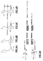
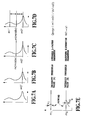
- the averaged Q-factor parameter evaluation step and the waveform distortion parameter evaluation step may comprise the steps of: estimating an amplitude histogram distribution function g1 associated with "level 1" from a portion of the amplitude histogram greater than a predetermined intensity threshold value (a); estimating an amplitude histogram distribution function g0 associated with "level 0" from a portion of the amplitude histogram less than another predetermined intensity threshold value (b); obtaining mean intensity values and standard deviations of "level 1" and "level 0" from the functions g1 and g0; calculating the averaged Q-factor parameter as a ratio of a difference between the mean intensity values of the "level 1” and “level 0" to the sum of the standard deviations of the "level 1” and “level 0”; and adopting at least one of the standard deviation of the "level 1", the standard deviation of the "level 0” , and the difference between the mean intensity values of the "level 1" and “level 0” as the waveform distortion parameter.
- the present invention includes a system for determining the origin of optical signal quality degradation, in which the steps of the method in accordance with the present invention are replaced by the corresponding means.
- the foregoing configuration can monitor the degradation factor of the optical signal quality.
- it can implement a low cost, highly reliable optical network capable of accommodating multimedia services that have large communication capability per service, and a variety of signal formats and signal bit rates.
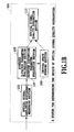
- Figs. 1A and 1B show a system for determining the origin of optical signal quality degradation of a first embodiment in accordance with the present invention.
- the system for determining the origin of optical signal quality degradation 101 of the present embodiment comprises an optical signal amplitude histogram measuring section 103, an averaged Q-factor parameter evaluation section 105, a waveform distortion parameter evaluation section 107, an initial state storing section 109 and an optical signal quality evaluation section 111.
- the optical signal amplitude histogram measuring section 103 obtains an optical amplitude histogram from the optical signal under measurement.
- the averaged Q-factor parameter evaluation section 105 obtains the averaged Q-factor parameter which is the optical signal quality parameter, from the optical signal amplitude histogram.
- the waveform distortion parameter evaluation section 107 obtains the waveform distortion parameter which is the optical signal quality parameter, from the optical signal amplitude histogram.
- the initial state storing section 109 stores into the storing medium the initial values or initial characteristics of the averaged Q-factor parameter and waveform distortion parameter at the system installation without the optical signal quality degradation.
- the optical signal quality evaluation section 111 evaluates an optical signal quality degradation factor using the measurement value of the averaged Q-factor parameter and the measurement value of the waveform distortion parameter, and the initial values or initial characteristics stored in the storing medium of the initial state storing section 109. In this case, the evaluation section 111 decides as to whether the main factor of the optical signal quality degradation is the waveform distortion in the optical signal under measurement or not by determining and evaluating both the averaged Q-factor parameter and waveform distortion parameter.
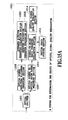
- Step 201 Evaluate (a) only the initial value, or (b) the optical signal-to-noise ratio degradation dependence of the averaged Q-factor parameter and waveform distortion parameter at the system installation without the signal degradation.
- Step 203 Store measurement results obtained at Step 201 into the initial state storing section 109 (see, Fig. 1A up to this step).
- Step 205 Evaluate the averaged Q-factor parameter and waveform distortion parameter at fixed time intervals after the start of the system operation.
- Step 207 Every time the averaged Q-factor parameter and waveform distortion parameter are measured, the optical signal quality evaluation section 111 compares the measurement values with the initial values or the optical signal-to-noise ratio degradation dependence graph in the initial state storing section 109.
- Step 209 When the degradation in the averaged Q-factor parameter from the initial value is observed, or when the averaged Q-factor parameter drops below a predetermined threshold value of the optical signal-to-noise ratio degradation dependence graph in the initial state storing section, the following decision is made:
- the optical signal amplitude histogram measuring section 103 is composed of an opto-electric converter 303, an electrical sampling oscilloscope 305 and a histogram evaluation section 307 as shown in Fig. 3, for example.
- the opto-electric converter 303 converts the optical signal under measurement with a bit rate of f 0 (bit/s) into an electric intensity modulated signal
- the histogram evaluation section 307 obtains the optical signal intensity distribution from the sampled signal obtained by the sampling oscilloscope 305 as illustrated in Figs. 5A and 5B, and obtains the optical signal amplitude histogram from the optical signal intensity distribution within a certain averaging time period.
- Fig. 4 shows another example of the optical signal amplitude histogram measuring section 103.
- the optical signal amplitude histogram measuring section 103 comprises an optical sampling oscilloscope 405 and a histogram evaluation section 307.
- the optical sampling oscilloscope 405 can utilize a known optical sampling method (Reference [3]: H. Takara, S. Kawanishi, A. Yokoo, S. Tomaru, T. Kitoh, and M. Saruwatari, "100 Gbit/s optical signal eye-diagram measurement with optical sampling using organic nonlinear optical crystal", Electron, Lett., 24, pp. 2256-2258, 1996).
- the sampling clock generating section can utilize electric short pulse generation by a synthesized signal generator plus comb generator. In addition, it can use an electric amplifier before or after the comb generator as needed, or a baseband clipper after the comb generator as needed.
- the optical gating section can employ the gating operation by an electro-absorption optical modulator.
- the averaged Q-factor parameter evaluation section 105 and the waveform distortion parameter evaluation section 107 as shown in Figs. 1A and 1B can utilize the evaluation method as illustrated in Figs. 6A-9C.
- the evaluation algorithm of the averaged Q-factor parameter and waveform distortion parameter as illustrated in Figs. 6A-6E is as follows.
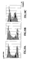
- Figs. 10A and 10C, and Figs. 11A and 11B illustrate actual measurement results in the present embodiment.
- Figs. 10A-10C illustrate the optical signal amplitude histograms obtained from a 10 Gbit/s NRZ optical signal.
- Fig. 10A illustrates the case where the chromatic dispersion value is 340 ps/nm, and the minimum receiving optical power is -31 dBm;
- Fig. 10B illustrates the case where the chromatic dispersion value is 1360 ps/nm, and the minimum receiving optical power is -31 dBm;
- Fig. 10C illustrates the case where the chromatic dispersion value is 340 ps/nm, and the minimum receiving optical power is -39 dBm.
- Figs. 10A and 10C show that when no waveform distortion due to the chromatic dispersion occurs, but the degradation in the optical signal-to-noise ratio takes place, the amplitude histograms vary in such a manner that the difference between the mean values at the level 1 and level 0 sharply reduces, so that the reduction in the averaged Q-factor is likely to take place.
- the inclination can be confirmed that the causes of the averaged Q-factor reduction differ in the case where only the waveform distortion occurs and only the degradation in the optical signal-to-noise ratio takes place.
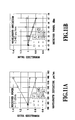
- Figs. 11A and 11B are graphs for confirming the foregoing considerations experimentally. Both the graphs plot the variations in the parameters on the assumption that the normalized value is one when the chromatic dispersion is 340 ps/nm and the minimum receiving optical power is -31 dBm.
- the graph of Fig. 11A illustrates, with respect to the variations in the chromatic dispersion, the variations in the averaged Q-factor parameter, the variations in the waveform distortion parameter s1 and the variations in difference between the mean values at the levels 0 and 1. It shows that as the chromatic dispersion (the waveform distortion) increases, the averaged Q-factor parameter reduces and the waveform distortion parameter s1 increases.
- the graph of Fig. 11B illustrates, with respect to the variations in the minimum receiving optical power, the variations in the averaged Q-factor parameter, the variations in the waveform distortion parameter s1 and the variations in the difference between the mean values at the levels 0 and 1. It shows that as the minimum receiving optical power (the optical signal-to-noise ratio) reduces, the averaged Q-factor parameter reduces and the waveform distortion parameter s1 varies only slightly. Thus, it can be distinguished from the waveform distortion of Fig. 11A.
- Figs. 12A and 12B show a system for determining the origin of optical signal quality degradation of a second embodiment in accordance with the present invention.
- the system for determining the origin of optical signal quality degradation 1201 of the present embodiment comprises an optical splitter 1203, an optical signal amplitude histogram measuring section 1205, an optical signal to optical noise power measuring section 1207, an averaged Q-factor parameter evaluation section 1209, an optical signal-to-noise ratio parameter evaluation section 1211, an initial state storing section 1213, and an optical signal quality evaluation section 1214.
- the optical splitter 1203 splits the optical signal under measurement.
- the optical signal amplitude histogram measuring section 1205 obtains the optical signal amplitude histogram from a first optical signal under measurement after the splitting.
- the optical signal to optical noise power measuring section 1207 measures the optical signal to optical noise power from a second optical signal under measurement after the splitting.
- the averaged Q-factor parameter evaluation section 1209 obtains the averaged Q-factor parameter which is the optical signal quality parameter, from the optical signal amplitude histogram obtained by the optical signal amplitude histogram measuring section 1205.
- the optical signal-to-noise ratio parameter evaluation section 1211 obtains the optical signal-to-noise ratio parameter which is the optical signal quality parameter, from the optical signal to optical noise power obtained by the optical signal amplitude histogram measuring section 1205.
- the initial state storing section 1213 stores into the storing medium the initial values or initial characteristics of the averaged Q-factor parameter and optical signal-to-noise ratio parameter at the system installation without the optical signal quality degradation.
- the optical signal quality evaluation section 1214 evaluates the optical signal quality degradation factor using the measurement value of the averaged Q-factor parameter and measurement value of the optical signal-to-noise ratio parameter, and the initial values or initial characteristics of the averaged Q-factor parameter and optical signal-to-noise ratio parameter at the system installation without the optical signal quality degradation, which are stored in the storing medium. In this case, it decides as to whether the main factor of the optical signal quality degradation is the degradation in the optical signal-to-noise ratio or not by determining and evaluating both the averaged Q-factor parameter and the optical signal-to-noise ratio parameter.
- Step 1301 Evaluate (a) only the initial values, or (b) the optical signal-to-noise ratio degradation dependence of the averaged Q-factor parameter and the optical signal-to-noise ratio parameter at the system installation without the signal degradation.
- Step 1303 Store measurement results obtained at Step 1301 into the initial state storing section 1213 (see, Fig. 12A up to this step).
- Step 1305 Evaluate the averaged Q-factor parameter and the optical signal-to-noise ratio parameter at fixed time intervals after the start of the system operation.
- Step 1307 Every time the averaged Q-factor parameter and the optical signal-to-noise ratio parameter are measured, the optical signal quality evaluation section 1214 compares the measurement values with the initial values or the optical signal-to-noise ratio degradation dependence graph in the initial state storing section 1213.
- Step 1309 When the degradation in the averaged Q-factor parameter from the initial value is observed, or when the averaged Q-factor parameter drops below a predetermined threshold value of the optical signal-to-noise ratio degradation dependence graph in the initial state storing section 1213, the following decision is made:
- the optical signal amplitude histogram measuring section 1205 can utilize a method using the electrical sampling or optical sampling as shown in the concrete examples of Figs. 3-5B, the details of which are described in the foregoing first embodiment.
- the averaged Q-factor parameter evaluation section 1209 can utilize the evaluation methods as shown in Figs. 6A-9C, the details of which are described in the foregoing first embodiment.
- the optical signal to optical noise power measuring section 1207 can utilize an optical spectrum analyzer, for example.
- optical signal-to-noise ratio parameter evaluation section 1211 can evaluate the optical signal-to-noise ratio parameter by the following expression as shown in Fig. 14.
- optical signal-to-noise ratio (OSNR) 10Log(optical signal power/optical noise power)
- Figs. 15A and 15B show a system for determining the origin of optical signal quality degradation of a third embodiment in accordance with the present invention.
- the system for determining the origin of optical signal quality degradation 1501 of the present embodiment comprises an optical splitter 1203, an optical signal amplitude histogram measuring section 1205, an optical signal to optical noise power measuring section 1207, an averaged Q-factor parameter evaluation section 1503, a waveform distortion parameter evaluation section 1505, an optical signal-to-noise ratio parameter evaluation section 1211, an initial state storing section 1213, and an optical signal quality evaluation section 1214.
- the optical splitter 1203 splits the optical signal under measurement.
- the optical signal amplitude histogram measuring section 1205 obtains the optical signal amplitude histogram from a first optical signal under measurement after the splitting.
- the optical signal to optical noise power measuring section 1207 measures the optical signal to optical noise power from a second optical signal under measurement after the splitting.
- the averaged Q-factor parameter evaluation section 1503 obtains the averaged Q-factor parameter which is the optical signal quality parameter, from the optical signal amplitude histogram.
- the waveform distortion parameter evaluation section 1505 obtains the waveform distortion parameter which is the optical signal quality parameter, from the optical signal amplitude histogram.
- the optical signal-to-noise ratio parameter evaluation section 1211 obtains the optical signal-to-noise ratio parameter which is the optical signal quality parameter, from the optical signal to optical noise power.
- the initial state storing section 1213 stores into the storing medium the initial values or initial characteristics of the averaged Q-factor parameter, waveform distortion prameter and optical signal-to-noise ratio parameter, at the system installation without the optical signal quality degradation.
- the optical signal quality evaluation section 1214 evaluates the optical signal quality degradation factor using the measurement value of the averaged Q-factor parameter, the measurement value of the waveform distortion parameter, and the measurement value of the optical signal-to-noise ratio parameter, and the initial values or initial characteristics at the system installation without the optical signal quality degradation, which are stored in the storing medium. In this case, it decides as to whether the main factor of the optical signal quality degradation is the degradation in the optical signal-to-noise ratio, or the waveform distortion or the other factors by determining and evaluating all the averaged Q-factor parameter, waveform distortion parameter, and optical signal-to-noise ratio parameter.
- Step 1601 Evaluate (a) only the initial values, or (b) the optical signal-to-noise ratio degradation dependence, of the averaged Q-factor parameter, waveform distortion parameter and optical signal-to-noise ratio parameter at the system installation without the signal degradation.
- Step 1603 Store measurement results obtained at Step 1601 into the initial state storing section 1213 (see, Fig. 15A up to this step).
- Step 1605 Evaluate the averaged Q-factor parameter, the waveform distortion parameter and the optical signal-to-noise ratio parameter at fixed time intervals after the start of the system operation.
- Step 1607 Every time the averaged Q-factor parameter, the waveform distortion parameter and the optical signal-to-noise ratio parameter are measured, the optical signal quality evaluation section 1214 compares the measurement values with the initial values or optical signal-to-noise ratio degradation dependence graph in the initial state storing section 1213.
- Step 1609 When the degradation in the averaged Q-factor parameter from the initial value is observed, or when the averaged Q-factor parameter drops below a predetermined threshold value of the optical signal-to-noise ratio degradation dependence graph in the initial state storing section 1213, the following decision is made:
- the optical signal amplitude histogram measuring section 1205 can utilize a method using the electrical sampling or optical sampling as shown in the concrete examples of Figs. 3-5B, the details of which are described in the foregoing first embodiment.
- the averaged Q-factor parameter evaluation section 1503 can utilize the evaluation methods as shown in Figs. 6A-9C, the details of which are described in the foregoing first embodiment.
- the optical signal to optical noise power measuring section 1207 and the optical signal-to-noise ratio parameter evaluation section 1211 can utilize an evaluation method as shown in Fig. 14, the details of which are described in the second embodiment.
Landscapes
- Physics & Mathematics (AREA)
- Electromagnetism (AREA)
- Engineering & Computer Science (AREA)
- Computer Networks & Wireless Communication (AREA)
- Signal Processing (AREA)
- Optical Communication System (AREA)
- Investigating, Analyzing Materials By Fluorescence Or Luminescence (AREA)
- Optical Transform (AREA)
- Testing Of Optical Devices Or Fibers (AREA)
Applications Claiming Priority (2)
| Application Number | Priority Date | Filing Date | Title |
|---|---|---|---|
| JP2001214212 | 2001-07-13 | ||
| JP2001214212 | 2001-07-13 |
Publications (3)
| Publication Number | Publication Date |
|---|---|
| EP1276253A2 true EP1276253A2 (de) | 2003-01-15 |
| EP1276253A3 EP1276253A3 (de) | 2004-03-31 |
| EP1276253B1 EP1276253B1 (de) | 2006-08-09 |
Family
ID=19049068
Family Applications (1)
| Application Number | Title | Priority Date | Filing Date |
|---|---|---|---|
| EP02254429A Expired - Lifetime EP1276253B1 (de) | 2001-07-13 | 2002-06-25 | Verfahren und Vorrichtung zur Bestimmung des Ursprungs des Qualitätsverlustes von optischen Signalen |
Country Status (4)
| Country | Link |
|---|---|
| US (1) | US7200328B2 (de) |
| EP (1) | EP1276253B1 (de) |
| AT (1) | ATE336114T1 (de) |
| DE (1) | DE60213726T2 (de) |
Cited By (2)
| Publication number | Priority date | Publication date | Assignee | Title |
|---|---|---|---|---|
| WO2007063533A1 (en) * | 2005-12-01 | 2007-06-07 | Eci Telecom Ltd. | Method and system for measuring average q-factor in optical networks |
| EP2214331A1 (de) * | 2009-02-03 | 2010-08-04 | Alcatel Lucent | Monitor mit optischer Kanalqualität |
Families Citing this family (13)
| Publication number | Priority date | Publication date | Assignee | Title |
|---|---|---|---|---|
| JP4468656B2 (ja) * | 2003-05-27 | 2010-05-26 | 株式会社日立製作所 | 信号波形劣化補償器 |
| DE10334428A1 (de) * | 2003-07-28 | 2005-02-24 | Siemens Ag | Verfahren zur Ermittlung der Qualität eines optischen Signals |
| CN1910843A (zh) * | 2004-06-03 | 2007-02-07 | 日本电信电话株式会社 | 光信号质量监控电路以及光信号质量监控方法 |
| US8625986B2 (en) * | 2006-09-27 | 2014-01-07 | Tti Inventions A Llc | Methods and systems for optical performance monitoring |
| EP2128577A4 (de) | 2007-01-09 | 2013-11-06 | Anritsu Corp | Abtastvorrichtung für synchronisation optischer signale, verfahren, dafür verwendete überwachungsvorrichtung für optische signale und verfahren |
| CA2640348A1 (en) * | 2007-01-15 | 2008-07-24 | Anritsu Corporation | Optical signal monitoring apparatus and method |
| EP2105720A4 (de) * | 2007-01-15 | 2013-11-06 | Anritsu Corp | Vorrichtung und verfahren zur überwachung der qualität optischer signale |
| US8615034B2 (en) * | 2008-10-19 | 2013-12-24 | Agilent Technologies, Inc. | Method for analyzing random telegraph signal and threshold level determination method therefor |
| JP6519117B2 (ja) | 2014-08-04 | 2019-05-29 | 富士通株式会社 | 光伝送装置、光伝送システム、及び、光伝送システムの制御装置 |
| US10079643B2 (en) * | 2016-11-23 | 2018-09-18 | Stmicroelectronics (Research & Development) Limited | Devices and methods for transmitting and receiving in an optical communications system |
| US10469176B2 (en) * | 2017-07-07 | 2019-11-05 | Inphi Corporation | Histogram based optimization for optical modulation |
| CN114204989B (zh) * | 2021-12-10 | 2023-06-16 | 中国电信股份有限公司 | 分光器数据的评估方法及装置、存储介质、电子设备 |
| EP4531304A1 (de) * | 2023-09-28 | 2025-04-02 | Nokia Solutions and Networks Oy | Verfahren und vorrichtung zur dsp-basierten parameteranalyse in passiven optischen netzwerken |
Family Cites Families (7)
| Publication number | Priority date | Publication date | Assignee | Title |
|---|---|---|---|---|
| EP0884868B1 (de) | 1997-06-09 | 2005-04-20 | Nortel Networks Limited | Messung der Augenöffnung von optischen Signalen mittels optischen Abtasten |
| JP3796357B2 (ja) | 1997-12-01 | 2006-07-12 | 日本電信電話株式会社 | 光信号品質モニタ |
| US6074057A (en) | 1998-05-22 | 2000-06-13 | Eastman Kodak Company | Pigmented ink jet inks and recording elements containing hardening agents |
| JP2000012240A (ja) | 1998-06-25 | 2000-01-14 | Matsushita Electric Works Ltd | 熱線センサ付自動スイッチ |
| US6404520B1 (en) * | 1998-12-21 | 2002-06-11 | Mci Worldcom, Inc. | Fault isolation of an optical link by correlating PMD events with other measurements |
| US6912359B2 (en) * | 2000-09-08 | 2005-06-28 | The Regents Of The University Of California | Methods for monitoring performance in optical networks |
| US6856767B2 (en) * | 2000-10-06 | 2005-02-15 | Alphion Corporation | Optical signal quality selection system |
-
2002
- 2002-06-19 US US10/173,752 patent/US7200328B2/en not_active Expired - Fee Related
- 2002-06-25 AT AT02254429T patent/ATE336114T1/de not_active IP Right Cessation
- 2002-06-25 DE DE60213726T patent/DE60213726T2/de not_active Expired - Lifetime
- 2002-06-25 EP EP02254429A patent/EP1276253B1/de not_active Expired - Lifetime
Non-Patent Citations (4)
| Title |
|---|
| HANIK N ET AL: "Application of amplitude histograms to monitor performance of optical channels" ELECTRONICS LETTERS, IEE STEVENAGE, GB, vol. 35, no. 5, 4 March 1999 (1999-03-04), pages 403-404, XP006011890 ISSN: 0013-5194 * |
| MUELLER K ET AL: "APPLICATION OF AMPLITUDE HISTOGRAMS FOR QUALITY OF SERVICE MEASUREMENTS OF OPTICAL CHANNELS AND FAULT IDENTIFICATION" PROCEEDINGS OF THE EUROPEAN CONFERENCE ON OPTICAL COMMUNICATION, XX, XX, vol. 1, 1998, pages 707-708, XP000887223 * |
| SHAKE I ET AL: "Optical signal quality monitoring method based on optical sampling" ELECTRONICS LETTERS, IEE STEVENAGE, GB, vol. 34, no. 22, 29 October 1998 (1998-10-29), pages 2152-2154, XP006010507 ISSN: 0013-5194 * |
| SHAKE I ET AL: "QUALITY MONITORING OF OPTICAL SIGNALS INFLUENCED BY CHROMATIC DISPERSION IN A TRANSMISSION FIBER USING AVERAGED Q-FACTOR EVALUATION" IEEE PHOTONICS TECHNOLOGY LETTERS, IEEE INC. NEW YORK, US, vol. 13, no. 4, April 2001 (2001-04), pages 385-387, XP001100911 ISSN: 1041-1135 * |
Cited By (2)
| Publication number | Priority date | Publication date | Assignee | Title |
|---|---|---|---|---|
| WO2007063533A1 (en) * | 2005-12-01 | 2007-06-07 | Eci Telecom Ltd. | Method and system for measuring average q-factor in optical networks |
| EP2214331A1 (de) * | 2009-02-03 | 2010-08-04 | Alcatel Lucent | Monitor mit optischer Kanalqualität |
Also Published As
| Publication number | Publication date |
|---|---|
| DE60213726D1 (de) | 2006-09-21 |
| DE60213726T2 (de) | 2007-08-16 |
| EP1276253A3 (de) | 2004-03-31 |
| US20030011837A1 (en) | 2003-01-16 |
| EP1276253B1 (de) | 2006-08-09 |
| US7200328B2 (en) | 2007-04-03 |
| ATE336114T1 (de) | 2006-09-15 |
Similar Documents
| Publication | Publication Date | Title |
|---|---|---|
| JP4180738B2 (ja) | デジタル信号品質モニタ方法とこの方法を用いた通信装置 | |
| EP1276253B1 (de) | Verfahren und Vorrichtung zur Bestimmung des Ursprungs des Qualitätsverlustes von optischen Signalen | |
| US7356256B1 (en) | Digital performance monitoring for an optical communications system | |
| Rossi et al. | Optical performance monitoring in reconfigurable WDM optical networks using subcarrier multiplexing | |
| US8660426B2 (en) | Optical signal to noise ratio monitoring technique and system | |
| US9337921B2 (en) | Method and apparatus for monitoring mechanical fiber stress of optical fiber spans | |
| JPH118590A (ja) | 光伝送システム及びその監視制御方法 | |
| Guesmi et al. | Experimental demonstration of simultaneous modulation format/symbol rate identification and optical performance monitoring for coherent optical systems | |
| JP2004336754A (ja) | 順方向誤り修正符号化を使用したqファクタのモニタリングのための方法と装置 | |
| US7079765B2 (en) | Optical wavelength division multiplex signal monitoring apparatus | |
| US20170126353A1 (en) | Wavelength shift elimination during spectral inversion in optical networks | |
| Kilper et al. | Monitoring optical network performance degradation due to amplifier noise | |
| JP3772132B2 (ja) | 光信号品質劣化要因監視方法および装置 | |
| Li et al. | In-service signal quality monitoring and multi-impairment discrimination based on asynchronous amplitude histogram evaluation for NRZ-DPSK systems | |
| Hu et al. | A novel cost-effective and distributed in-band OSNR monitoring method using Gaussian process regression | |
| JP3642710B2 (ja) | 光受信器,光送信器,光増幅中継器及び光信号監視システム | |
| JP4129005B2 (ja) | 光信号品質劣化要因監視方法および装置 | |
| Downie et al. | Performance monitoring of optical networks with synchronous and asynchronous sampling | |
| André et al. | Optical-signal-quality monitor for bit-error-ratio assessment in transparent DWDM networks based on asynchronously sampled amplitude histograms | |
| JP2003209522A (ja) | 光波長分割多重信号監視装置および方法、並びに光信号品質監視装置および光信号波形測定装置 | |
| Chen et al. | Transparent monitoring of rise time using asynchronous amplitude histograms in optical transmission systems | |
| André et al. | Bit error rate assessment in DWDM transparent networks using optical performance monitor based in asynchronous sampling | |
| Kilper et al. | Q-factor monitoring using FEC for fault-management applications | |
| Zhou et al. | Bit-rate identification using asynchronous delayed sampling | |
| Ye et al. | Improved BER monitoring based on amplitude histogram and multi-Gaussian curve fitting |
Legal Events
| Date | Code | Title | Description |
|---|---|---|---|
| PUAI | Public reference made under article 153(3) epc to a published international application that has entered the european phase |
Free format text: ORIGINAL CODE: 0009012 |
|
| AK | Designated contracting states |
Kind code of ref document: A2 Designated state(s): AT BE CH CY DE DK ES FI FR GB GR IE IT LI LU MC NL PT SE TR |
|
| AX | Request for extension of the european patent |
Free format text: AL;LT;LV;MK;RO;SI |
|
| PUAL | Search report despatched |
Free format text: ORIGINAL CODE: 0009013 |
|
| AK | Designated contracting states |
Kind code of ref document: A3 Designated state(s): AT BE CH CY DE DK ES FI FR GB GR IE IT LI LU MC NL PT SE TR |
|
| AX | Request for extension of the european patent |
Extension state: AL LT LV MK RO SI |
|
| 17P | Request for examination filed |
Effective date: 20040927 |
|
| 17Q | First examination report despatched |
Effective date: 20041029 |
|
| AKX | Designation fees paid |
Designated state(s): AT BE CH CY DE DK ES FI FR GB GR IE IT LI LU MC NL PT SE TR |
|
| GRAP | Despatch of communication of intention to grant a patent |
Free format text: ORIGINAL CODE: EPIDOSNIGR1 |
|
| RTI1 | Title (correction) |
Free format text: METHOD AND SYSTEM FOR DETERMINING THE ORIGIN OF OPTICAL SIGNAL QUALITY DEGRADATION |
|
| RIN1 | Information on inventor provided before grant (corrected) |
Inventor name: TAKARA, HIDEHIKO,C/O NTT INTEL. PROP. CENTER Inventor name: UCHIYAMA, KENTARO,C/O NTT INTEL. PROP. CENTER Inventor name: SHAKE, IPPEI,C/O NTT INTEL. PROP. CENTER |
|
| GRAS | Grant fee paid |
Free format text: ORIGINAL CODE: EPIDOSNIGR3 |
|
| GRAA | (expected) grant |
Free format text: ORIGINAL CODE: 0009210 |
|
| AK | Designated contracting states |
Kind code of ref document: B1 Designated state(s): AT BE CH CY DE DK ES FI FR GB GR IE IT LI LU MC NL PT SE TR |
|
| PG25 | Lapsed in a contracting state [announced via postgrant information from national office to epo] |
Ref country code: IT Free format text: LAPSE BECAUSE OF FAILURE TO SUBMIT A TRANSLATION OF THE DESCRIPTION OR TO PAY THE FEE WITHIN THE PRESCRIBED TIME-LIMIT;WARNING: LAPSES OF ITALIAN PATENTS WITH EFFECTIVE DATE BEFORE 2007 MAY HAVE OCCURRED AT ANY TIME BEFORE 2007. THE CORRECT EFFECTIVE DATE MAY BE DIFFERENT FROM THE ONE RECORDED. Effective date: 20060809 Ref country code: NL Free format text: LAPSE BECAUSE OF FAILURE TO SUBMIT A TRANSLATION OF THE DESCRIPTION OR TO PAY THE FEE WITHIN THE PRESCRIBED TIME-LIMIT Effective date: 20060809 Ref country code: LI Free format text: LAPSE BECAUSE OF FAILURE TO SUBMIT A TRANSLATION OF THE DESCRIPTION OR TO PAY THE FEE WITHIN THE PRESCRIBED TIME-LIMIT Effective date: 20060809 Ref country code: CH Free format text: LAPSE BECAUSE OF FAILURE TO SUBMIT A TRANSLATION OF THE DESCRIPTION OR TO PAY THE FEE WITHIN THE PRESCRIBED TIME-LIMIT Effective date: 20060809 Ref country code: BE Free format text: LAPSE BECAUSE OF FAILURE TO SUBMIT A TRANSLATION OF THE DESCRIPTION OR TO PAY THE FEE WITHIN THE PRESCRIBED TIME-LIMIT Effective date: 20060809 Ref country code: AT Free format text: LAPSE BECAUSE OF FAILURE TO SUBMIT A TRANSLATION OF THE DESCRIPTION OR TO PAY THE FEE WITHIN THE PRESCRIBED TIME-LIMIT Effective date: 20060809 Ref country code: FI Free format text: LAPSE BECAUSE OF FAILURE TO SUBMIT A TRANSLATION OF THE DESCRIPTION OR TO PAY THE FEE WITHIN THE PRESCRIBED TIME-LIMIT Effective date: 20060809 |
|
| REG | Reference to a national code |
Ref country code: GB Ref legal event code: FG4D |
|
| REG | Reference to a national code |
Ref country code: CH Ref legal event code: EP |
|
| REG | Reference to a national code |
Ref country code: IE Ref legal event code: FG4D |
|
| REF | Corresponds to: |
Ref document number: 60213726 Country of ref document: DE Date of ref document: 20060921 Kind code of ref document: P |
|
| PG25 | Lapsed in a contracting state [announced via postgrant information from national office to epo] |
Ref country code: DK Free format text: LAPSE BECAUSE OF FAILURE TO SUBMIT A TRANSLATION OF THE DESCRIPTION OR TO PAY THE FEE WITHIN THE PRESCRIBED TIME-LIMIT Effective date: 20061109 Ref country code: SE Free format text: LAPSE BECAUSE OF FAILURE TO SUBMIT A TRANSLATION OF THE DESCRIPTION OR TO PAY THE FEE WITHIN THE PRESCRIBED TIME-LIMIT Effective date: 20061109 |
|
| PG25 | Lapsed in a contracting state [announced via postgrant information from national office to epo] |
Ref country code: ES Free format text: LAPSE BECAUSE OF FAILURE TO SUBMIT A TRANSLATION OF THE DESCRIPTION OR TO PAY THE FEE WITHIN THE PRESCRIBED TIME-LIMIT Effective date: 20061120 |
|
| PG25 | Lapsed in a contracting state [announced via postgrant information from national office to epo] |
Ref country code: PT Free format text: LAPSE BECAUSE OF FAILURE TO SUBMIT A TRANSLATION OF THE DESCRIPTION OR TO PAY THE FEE WITHIN THE PRESCRIBED TIME-LIMIT Effective date: 20070109 |
|
| ET | Fr: translation filed | ||
| NLV1 | Nl: lapsed or annulled due to failure to fulfill the requirements of art. 29p and 29m of the patents act | ||
| REG | Reference to a national code |
Ref country code: CH Ref legal event code: PL |
|
| PLBE | No opposition filed within time limit |
Free format text: ORIGINAL CODE: 0009261 |
|
| STAA | Information on the status of an ep patent application or granted ep patent |
Free format text: STATUS: NO OPPOSITION FILED WITHIN TIME LIMIT |
|
| 26N | No opposition filed |
Effective date: 20070510 |
|
| PG25 | Lapsed in a contracting state [announced via postgrant information from national office to epo] |
Ref country code: MC Free format text: LAPSE BECAUSE OF NON-PAYMENT OF DUE FEES Effective date: 20070630 |
|
| PG25 | Lapsed in a contracting state [announced via postgrant information from national office to epo] |
Ref country code: GR Free format text: LAPSE BECAUSE OF FAILURE TO SUBMIT A TRANSLATION OF THE DESCRIPTION OR TO PAY THE FEE WITHIN THE PRESCRIBED TIME-LIMIT Effective date: 20061110 |
|
| PG25 | Lapsed in a contracting state [announced via postgrant information from national office to epo] |
Ref country code: IE Free format text: LAPSE BECAUSE OF NON-PAYMENT OF DUE FEES Effective date: 20070625 |
|
| PG25 | Lapsed in a contracting state [announced via postgrant information from national office to epo] |
Ref country code: CY Free format text: LAPSE BECAUSE OF FAILURE TO SUBMIT A TRANSLATION OF THE DESCRIPTION OR TO PAY THE FEE WITHIN THE PRESCRIBED TIME-LIMIT Effective date: 20060809 Ref country code: LU Free format text: LAPSE BECAUSE OF NON-PAYMENT OF DUE FEES Effective date: 20070625 |
|
| PG25 | Lapsed in a contracting state [announced via postgrant information from national office to epo] |
Ref country code: TR Free format text: LAPSE BECAUSE OF FAILURE TO SUBMIT A TRANSLATION OF THE DESCRIPTION OR TO PAY THE FEE WITHIN THE PRESCRIBED TIME-LIMIT Effective date: 20060809 |
|
| REG | Reference to a national code |
Ref country code: FR Ref legal event code: PLFP Year of fee payment: 15 |
|
| PGFP | Annual fee paid to national office [announced via postgrant information from national office to epo] |
Ref country code: GB Payment date: 20160621 Year of fee payment: 15 Ref country code: DE Payment date: 20160621 Year of fee payment: 15 |
|
| PGFP | Annual fee paid to national office [announced via postgrant information from national office to epo] |
Ref country code: FR Payment date: 20160627 Year of fee payment: 15 |
|
| REG | Reference to a national code |
Ref country code: DE Ref legal event code: R119 Ref document number: 60213726 Country of ref document: DE |
|
| GBPC | Gb: european patent ceased through non-payment of renewal fee |
Effective date: 20170625 |
|
| REG | Reference to a national code |
Ref country code: FR Ref legal event code: ST Effective date: 20180228 |
|
| PG25 | Lapsed in a contracting state [announced via postgrant information from national office to epo] |
Ref country code: DE Free format text: LAPSE BECAUSE OF NON-PAYMENT OF DUE FEES Effective date: 20180103 Ref country code: GB Free format text: LAPSE BECAUSE OF NON-PAYMENT OF DUE FEES Effective date: 20170625 |
|
| PG25 | Lapsed in a contracting state [announced via postgrant information from national office to epo] |
Ref country code: FR Free format text: LAPSE BECAUSE OF NON-PAYMENT OF DUE FEES Effective date: 20170630 |