EP1276255B1 - Optisches Zwischenverstärkersystem und Verstärkersteuerverfahren - Google Patents
Optisches Zwischenverstärkersystem und Verstärkersteuerverfahren Download PDFInfo
- Publication number
- EP1276255B1 EP1276255B1 EP02015525A EP02015525A EP1276255B1 EP 1276255 B1 EP1276255 B1 EP 1276255B1 EP 02015525 A EP02015525 A EP 02015525A EP 02015525 A EP02015525 A EP 02015525A EP 1276255 B1 EP1276255 B1 EP 1276255B1
- Authority
- EP
- European Patent Office
- Prior art keywords
- optical
- signal
- supervisory
- command
- sub
- Prior art date
- Legal status (The legal status is an assumption and is not a legal conclusion. Google has not performed a legal analysis and makes no representation as to the accuracy of the status listed.)
- Expired - Lifetime
Links
Images


Classifications
-
- H—ELECTRICITY
- H04—ELECTRIC COMMUNICATION TECHNIQUE
- H04B—TRANSMISSION
- H04B10/00—Transmission systems employing electromagnetic waves other than radio-waves, e.g. infrared, visible or ultraviolet light, or employing corpuscular radiation, e.g. quantum communication
- H04B10/07—Arrangements for monitoring or testing transmission systems; Arrangements for fault measurement of transmission systems
- H04B10/075—Arrangements for monitoring or testing transmission systems; Arrangements for fault measurement of transmission systems using an in-service signal
- H04B10/077—Arrangements for monitoring or testing transmission systems; Arrangements for fault measurement of transmission systems using an in-service signal using a supervisory or additional signal
- H04B10/0777—Monitoring line amplifier or line repeater equipment
-
- H—ELECTRICITY
- H04—ELECTRIC COMMUNICATION TECHNIQUE
- H04B—TRANSMISSION
- H04B10/00—Transmission systems employing electromagnetic waves other than radio-waves, e.g. infrared, visible or ultraviolet light, or employing corpuscular radiation, e.g. quantum communication
- H04B10/29—Repeaters
- H04B10/291—Repeaters in which processing or amplification is carried out without conversion of the main signal from optical form
- H04B10/298—Two-way repeaters, i.e. repeaters amplifying separate upward and downward lines
-
- H—ELECTRICITY
- H04—ELECTRIC COMMUNICATION TECHNIQUE
- H04B—TRANSMISSION
- H04B2210/00—Indexing scheme relating to optical transmission systems
- H04B2210/07—Monitoring an optical transmission system using a supervisory signal
- H04B2210/074—Monitoring an optical transmission system using a supervisory signal using a superposed, over-modulated signal
Definitions
- the present invention relates to an optical repeating system that comprises an uplink optical transmission line, a downlink optical transmission line, an optical transmitter and an optical receiver for transferring a main signal through the uplink or downlink optical transmission line, and a plurality of optical amplifying repeaters for amplifying and repeating the main signal with optical amplifiers at intermediate positions on the optical transmission lines, and to an optical amplifying repeater control method for controlling the optical amplifying repeaters.
- Fig. 4 is a block diagram showing a configuration of a conventional optical repeating system disclosed in JP2716882B2.
- the reference numeral 1 designates an optical transmitter for transmitting a main signal conveying information and a first sub-signal bearing a command for an optical amplifying repeater 3
- 2 designates an optical fiber constituting an optical transmission line for interconnecting the optical transmitter 1, optical amplifying repeaters 3 and an optical receiver 4
- 3 designates an optical amplifying repeater located at an intermediate position on the optical fiber 2 for not only amplifying and transmitting the main signal with an optical amplifier, but also for superimposing the supervisory information obtained from the command conveyed by the first sub-signal on the main signal as a second sub-signal
- 4 designates an optical receiver for receiving the main signal and the like.
- Fig. 5 is a block diagram showing a configuration of the optical amplifying repeater as shown in Fig. 4.
- the reference numeral 101 designates a coupler for splitting the input optical signal
- 102 designates an optical amplifier comprising an isolator 111, a pumping laser diode 112, a multiplexing filter 113, an erbium (Er) doped optical fiber 114, and an isolator 115
- 103 designates a coupler for splitting an optical signal output from the optical amplifier 102, and for outputting its first part as the output optical signal.
- Fig. 6 is a block diagram showing a configuration of the optical transmitter 1 in Fig. 4.
- the reference numeral 201 designates a main signal circuit for outputting the main signal used for information transmission;
- 202 designates a sub-signal circuit for outputting the first sub-signal containing the operation command that specifies the optical amplifying repeater;
- 203 designates a modulator for superimposing the first sub-signal on the main signal in a prescribed modulating scheme;
- 204 designates a driver supplied with the main signal on which the first sub-signal is superimposed for driving a semiconductor laser 205;
- 205 designates the semiconductor laser for supplying the optical fiber 2 with the optical signal corresponding to the applied electrical signal.
- Fig. 7 is a block diagram showing a configuration of the optical receiver in Fig. 4.
- the reference numeral 301 designates a photoelectric converter for converting the input optical signal fed from the optical fiber 2 to an electrical signal;
- 302 designates an amplifier for amplifying the electrical signal;
- 303 designates amain signal demodulator for demodulating the main signal in the received signal;
- 304 designates a low-pass filter for filtering the first and second sub-signals in the received signal;
- 305 designates a sub-signal demodulator for demodulating the first and second sub-signals in the received signal.
- the sub-signal circuit 202 generates the first sub-signal, which includes the operation command specifying one of the optical amplifying repeaters 3 by an address code uniquely assigned to each optical amplifying repeater, in such a manner that its amplitude is smaller and its rate is lower than those of the main signal output from the main signal circuit 201.
- the modulator 203 supplies the driver 204 with the main signal on which the first sub-signal is superimposed.
- the output optical signal of the semiconductor laser 205 consists of the modulation signal of the main signal plus the first sub-signal superimposed thereon.
- the optical transmitter 1 transmits the operation command to the next optical amplifying repeater 3 as the first sub-signal in such a manner that an appropriate time interval is reserved after the first sub-signal including the operation command.
- the reserved time interval enables the specified optical amplifying repeater 3 to transmit a supervisory signal corresponding to the first sub-signal during the reserved time interval as the second sub-signal.
- the coupler 101 splits the input optical signal fed from the input side optical fiber 2.
- a first part of the split input optical signal is launched into the optical amplifier 102 to be amplified.
- a second part of the split input optical signal is launched into the photoelectric converter 121 to be converted to the electrical signal.
- the electrical signal is amplified by the amplifier 122, and then the low-pass filter 123 extracts the first sub-signal with a frequency lower than the frequency of the main signal, and supplies it to the incoming call identification circuit 124.
- the incoming call identification circuit 124 makes a decision as to whether the optical transmitter 1 sends the operation command to this repeater from the address code contained in the first sub-signal, and notifies the controller 125 of the decision result.
- the controller 125 actuates the encoder 131 and the modulator 132 to modulate the driving current to be supplied from the pumping laser diode driver 133 to the pumping laser diode 112 by the second sub-signal including the intra-repeater information. Since the driving current to the pumping laser diode 112 is modulated by the second sub-signal, the amplification factor of the optical amplifier 102 is modulated.
- the optical signal output from the optical amplifier 102 consists of the main signal and he second sub-signal superimposed thereon.
- the controller 125 does not actuate the encoder 131 nor the modulator 132.
- the pumping laser diode 112 is driven by a non-modulated driving current.
- the input optical signal fed from the optical fiber 2 is converted by the photoelectric converter 301 into an electrical signal which is amplified by the amplifier 302.
- the amplified electrical signal is supplied to the main signal demodulator 303.
- the low-pass filter 304 extracts the first and second sub-signals from the electrical signal, and supplies them to the sub-signal demodulator 305.
- the sub-signal demodulator 305 demodulates the operation command, which is addressed to the optical amplifying repeater 3, from the first sub-signal transmitted from the optical transmitter 1, and the intra-repeater information from the second sub-signal transmitted from the optical amplifying repeater 3.
- the operation state of each optical amplifying repeater 3 can be supervised.
- the optical transmitter 1 selects one of the optical amplifying repeaters 3 one by one, and transmits the operation command by superimposing it on the main signal. Receiving the operation command addressed to it, each optical amplifying repeater 3 superimposes the supervisory information about the repeater on the main signal, and sends it to the optical receiver 4. The optical receiver 4 demodulates the supervisory information sent from the optical amplifying repeaters 3 sequentially.
- the conventional optical repeating system can supervise each of the optical amplifying repeaters 3.
- the conventional optical repeating system has a problem in that it is difficult to adjust the amplification factor of the optical amplifier 102 of the optical amplifying repeater 3, and to stabilize the amplification characteristics of the optical amplifying repeater 3 over the long run.
- the present invention is implemented to solve the foregoing problem. It is therefore an object of the present invention to provide an optical repeating system and optical amplifying repeater control method capable of stabilizing the amplification characteristics of the optical amplifying repeaters by adjusting the amplification factors of the optical amplifiers of the optical amplifying repeaters.
- an optical repeating system comprising: an uplink optical transmission line; a downlink optical transmission line; an optical transmitter and an optical receiver for transmitting and receiving a main signal via at least one of the uplink and downlink optical transmission lines; and a plurality of optical amplifying repeaters each installed at an intermediate position on the optical transmission lines for amplifying and repeating the main signal with optical amplifiers, wherein the optical transmitter specifies one of the plurality of optical amplifying repeaters, and transmits a first sub-signal containing at least one of a supervisory command and a control command to the specified optical amplifying repeater, the supervisory command commanding to supervise internal circuits of the optical amplifying repeater, and the control command commanding to control amplification factors of the optical amplifiers, and wherein the optical amplifying repeater transmits, when receiving the supervisory command via one of the uplink and downlink optical transmission lines, a second sub-signal to the optical receiver via the uplink optical transmission line and the downlink optical
- the optical repeating system may further comprise a feeder line installed along the optical transmission lines; and a feeding circuit installed at each end of the feeder line for feeding the plurality of optical amplifying repeaters with a current via the feeder line.
- an optical amplifying repeater control method of controlling an optical amplifying repeater in an optical repeating system including an uplink optical transmission line, a downlink optical transmission line, an optical transmitter and an optical receiver for transmitting and receiving a main signal via at least one of the uplink and downlink optical transmission lines, and a plurality of optical amplifying repeaters each installed at an intermediate position on the optical transmission lines for amplifying and repeating the main signal with optical amplifiers
- the optical amplifying repeater control method comprising the steps of: specifying one of the plurality of optical amplifying repeaters, and transmitting a first sub-signal containing at least one of a supervisory command and a control command to the specified optical amplifying repeater by the optical transmitter, the supervisory command commanding to supervise internal circuits of the optical amplifying repeater, and the control command commanding to control amplification factors of the optical amplifiers; receiving at least one of the supervisory command and the control command by the optical amplifying repeater via one of
- Fig. 1 is a block diagram showing a configuration of an embodiment 1 of the optical repeating system in accordance with the present invention.
- the reference numeral 601 designates a line supervisory unit.
- the line supervisory unit 601 comprises optical transmitters 611 and optical receivers 612 serving as terminals of uplink and downlink bidirectional optical transmission lines, each of which consists of the optical fibers 602-1 and 602-2.
- the line supervisory unit 601 further comprises a feeding circuit 613 for supplying current to each optical amplifying repeater 603 via a feeder line 614.
- the optical transmitters 611 and optical receivers 612 have the same configuration as those of Figs. 6 and 7.
- reference numerals 602-1 and 602-2 each designate an optical fiber constituting the bidirectional optical transmission line; and 603 designates an optical amplifying repeater that amplifies main signals on a plurality of bidirectional optical transmission lines, and that comprises a plurality of sub-modules 621 for receiving the first sub-signal and carries out the processing thereof.
- a pair of the bidirectional optical transmission lines are installed, where each bidirectional optical transmission line is defined as an optical fiber pair 604 consisting of the optical fiber 602-1 and optical fiber 602-2.
- the reference numeral 631-1 designates an optical amplifier mounted on the uplink optical transmission line (optical fiber 602-1) for amplifying the main signal
- 631-2 designates an optical amplifier mounted on the downlink optical transmission line (optical fiber 602-2) for amplifying the main signal
- 632 designates a supervisory controller that transmits, when receiving the supervisory command addressed to the repeater from the optical transmitter 611 via the uplink optical transmission line or the downlink optical transmission line, the supervisory signal indicating the supervisory result corresponding to the supervisory command to the optical receivers 612 via the uplink optical transmission line and downlink optical transmission line as the second sub-signal, and that controls, when receiving the control command via the uplink optical transmission line (or the downlink optical transmission line), the amplification factor of the optical amplifier 631-1 (optical amplifier 631-2) in accordance with the control command.
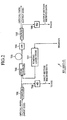
- Fig. 2 is a block diagram showing a configuration of the optical amplifier 631-1 or 631-2 as shown in Fig. 1.
- the reference numeral 701 designates a coupler for splitting the input optical signal
- 702 designates a WDM (Wavelength Division Multiplexing) coupler for combining the optical signal with the pumping laser light
- 703 designates an erbium (Er) doped fiber
- 704 designates an isolator
- 705 designates a coupler for splitting the amplified optical signal, and outputting its first part as the output optical signal.
- the reference numeral 706 designates a photoelectric converter for converting the optical signal into an electrical signal
- 707 designates a pumping laser diode for applying the pumping laser light to the erbium (Er) doped fiber 703 via the WDM coupler 702
- 708 designates a photoelectric converter for converting the optical signal to an electrical signal.
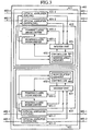
- Fig. 3 is a block diagram showing a configuration of the optical amplifying repeater 603 as shown in Fig. 1.
- the reference numeral 651 designates a modem unit.
- the modem unit 651 extracts and demodulates the first sub-signal sent from the optical transmitter 611 of the line supervisory unit 601. It also modulates the driving current to the pumping laser diode 707 by the supervisory signal that includes various items of the intra-repeater information corresponding to the supervisory command. It carries out the modulation by controlling the pumping laser diode drivers 653-1 and 653-2, thereby superimposing the supervisory signal on the main signal as the second sub-signal.
- the reference numeral 652 designates a controller that operates as follows.
- the controller 652 When detecting the supervisory command addressed to the repeater from the first sub-signal, the controller 652 collects the intra-repeater information, and supplies the modem unit 651 with the supervisory signal indicating the intra-repeater information. On the other hand, when detecting the control command addressed to the repeater from the first sub-signal, it controls the amplification factors of the pumping laser diode drivers 653-1 and 653-2, thereby controlling the optical amplifiers 631-1 and 631-2.
- the reference numeral 661 designates a nonvolatile memory such as an FRAM (Ferro-electric Random Access Memory) and MRAM (Magneto-resistive Random Access Memory) for storing the set values of the amplification factors of the optical amplifiers 631-1 and 631-2, the intra-repeater information and the like.
- the reference numeral 653-1 designates the pumping laser diode driver for supplying the driving current to the pumping laser diode 707 of the optical amplifier 631-1; and 653-2 designates a pumping laser diode driver for supplying the driving current to the pumping laser diode 707 of the optical amplifier 631-2.
- the feeding circuits 613 of the line supervisory units 601 at both ends of the optical transmission line feed a current to the individual optical amplifying repeaters 603 through the feeder line 614.
- the optical transmitter 611 of the line supervisory unit 601 transmits the main signal to the optical receiver 612 of the far-end line supervisory unit 601.
- the optical transmitter 611 when transmitting a supervisory command or control command to a specified optical amplifying repeater 603, the optical transmitter 611 superimposes on the main signal the first sub-signal that contains the address code uniquely assigned to the specified optical amplifying repeater 603 and the supervisory command or control command.
- the optical transmitter 611 modulates a carrier by the main signal, superimposes the first sub-signal, converts the resultant electrical signal to the optical signal, and supplies the optical signal to the optical fiber 602-1 (or 602-2).
- the optical amplifying repeater 603 operates as follows. First, the coupler 701 splits the optical signal, and supplies a first part of the optical signal to the Er doped optical fiber 703 via the WDM coupler 702. In this case, the WDM coupler 702 combines the first part of the optical signal with the pumping laser light fed from the pumping laser diode 707. Then, the optical signal amplified by the Er doped optical fiber 703 is launched into the coupler 705 via the isolator 704 to be split by the coupler 705, and a first part of the split optical signal is supplied to the optical fiber 602-1 (602-2). Thus, the main signal is amplified and repeated by the optical amplifier 631-1 (631-2) of the optical amplifying repeater 603.
- a second part of the optical signal split by the coupler 701 is converted into an electrical signal by the photoelectric converter 706, and the electrical signal is supplied to the modem unit 651 of the supervisory controller 632.
- a second part of the optical signal split by the coupler 705 is converted into an electrical signal by the photoelectric converter 708, and the electrical signal is supplied to the modem unit 651 of the supervisory controller 632.
- the modem unit 651 extracts and demodulates only the first sub-signal from the electrical signal fed from the photoelectric converter 706, and supplies it to the controller 652.
- the modem unit 651 also measures the power level of the output optical signal from the electrical signal fed from the photoelectric converter 708, and notifies the controller 652 of the power level.
- the controller 652 referring to its uniquely assigned address code that is stored in the nonvolatile memory 661, makes a decision as to whether the first sub-signal contains the same address code as the uniquely assigned address code. When the first sub-signal contains the same address code as the uniquely assigned address code, the controller 652 performs the processing corresponding to the supervisory command or control command contained in the first sub-signal. On the other hand, when the first sub-signal does not include the same address code as the uniquely assigned address code, the controller 652 disregards the first sub-signal.
- the controller 652 collects the intra-repeater information in response to the supervisory command.
- the intra-repeater information includes such information items as the modulation factors of the first and second sub-signals (described later) (the amplitude intensity of the first and second sub-signals) in terms of the main signal, the power levels of the input and output optical signals of the optical amplifying repeater 603, the amplification factors of the optical amplifiers 631-1 and 631-2, and the driving current level for the pumping laser diode 707.
- the supervisory command there are a start command for starting collection of the intra-repeater information, a selection command for selecting information to be transmitted to the optical receiver 612 from the intra-repeater information after collecting the intra-repeater information, and a transmission command for transmitting the selected information.
- the optical transmitter 611 sends the start command, and then the selection command after a sufficient time period has elapsed to collect the intra-repeater information, followed by sending the transmission command.
- the these commands can be sent at once as a single command instead of sending them step by step.
- the controller 652 After collecting the intra-repeater information, the controller 652 converts the analog values of the information to digital data, and supplies the data to the modem unit 651.
- the modem unit 651 generates the supervisory signal by modulating a prescribed subcarrier different from the carrier of the main signal. Then, the modem unit 651 modulates the driving current of the pumping laser diode 707 in the optical amplifier 631-1 and that of the pumping laser diode 707 in the optical amplifier 631-2 by the supervisory signal by controlling the pumping laser diode drivers 653-1 and 653-2, thereby superimposing the supervisory signal on both the uplink and downlink main signals as the second sub-signal. In the course of this, the controller 652 generates the digital data within a predetermined quantization error, temporarily stores the data in a memory not shown, and reads the data of the selected supervisory information from the memory when it detects the selection command.
- the controller 652 controls the internal circuits such as the modem unit 651 and pumping laser diode drivers 653-1 and 653-2 in response to the control command.
- control command there are a reset command for resetting the operation state of the supervisory controller 632 into its initial state, an amplification factor control command for controlling the amplification factors of the optical amplifiers 631-1 and 631-2, and an amplitude intensity control command for controlling the amplitude intensity of the second sub-signal.
- the controller 652 When detecting the reset command, the controller 652 resets the operation state of the supervisory controller 632 into its initial state. When detecting the amplification factor control command, it controls the pumping laser diode drivers 653-1 and 653-2 to control the amplification factors of the optical amplifiers 631-1 and 631-2 by adjusting the driving currents to the pumping laser diodes 707. When detecting the amplitude intensity control command, the controller 652 controls the amplitude intensity of the second sub-signal by controlling the modem unit 651 or the pumping laser diode drivers 653-1 and 653-2.
- the controller 652 can set the amplitude intensity of the second sub-signal to the modem unit 651 in the form of m-bit digital data via m signal lines, or in the form of an analog value via a single signal line.
- the controller 652 reads it to check whether it is set at a correct value in accordance with the control command, and makes it one of the intra-repeater information items.
- the optical receiver 612 in the far-end line supervisory unit 601 opposing to the line supervisory unit 601 that transmits the supervisory command receives the optical signal via the optical fiber 602-1 or 602-2. After converting the optical signal to the electrical signal, the optical receiver 612 demodulates it to the main signal and first and second sub-signals . Likewise, the optical receiver 612 of the line supervisory unit 601 that transmits the supervisory command receives the second sub-signal via the reverse direction optical fiber 602-2 or 602-1.
- the line supervisory unit 601 displays the supervisory information obtained from the second sub-signal on a display not shown or prints it out by a printer not shown.
- the supervisory controller 632 When the supervisory controller 632 does not receive the command addressed thereto, it only drives the pumping laser diodes 707 with a reference current without performing the superimposition of the second sub-signal. Incidentally, the supervision and control of the optical amplifying repeater 603 can be achieved for individual sub-modules 621 via the optical transmission line.
- the present embodiment 1 is configured such that the transmitter 611 transmits the supervisory command to the optical amplifying repeater 603, which in turn transmits the supervisory signal to the optical receivers 612 of the line supervisory units 601 at both ends via both the optical transmission lines in response to the supervisory command.
- the line supervisory unit 601 that transmits the supervisory command can acquire the supervisory information corresponding to the supervisory command in a short time.
- the present embodiment 1 offers an advantage of being able to supervise the individual optical amplifying repeaters 603 quickly, particularly when the supervisory commands are transmitted successively.
- the present embodiment 1 is configured such that it can control the amplification factors of the optical amplifiers 631-1 and 631-2 and the amplitude intensity of the second sub-signal of each optical amplifying repeater 603 individually.
- the present embodiment 1 offers an advantage of being able to control the characteristics of the individual optical amplifying repeaters 603 step by step so that the total gain characteristic of the plurality of optical amplifying repeaters 603 is adjusted to a desired level.
- the present embodiment 1 offers an advantage of being able to maintain the amplification factors of the optical amplifying repeaters 603 by adjusting the amplification factors of the optical amplifiers 631-1 and 631-2.
- the present embodiment 1 is configured such that the feeding circuits 613 installed at both ends of the feeder line 614 supply current to the optical amplifying repeaters 603.
- the present embodiment 1 offers an advantage of being able to shorten the average distance from the feeding circuits 613 to the plurality of optical amplifying repeaters 603, thereby making it possible to decrease the supply voltage reduction to the optical amplifying repeaters 603.
Landscapes
- Physics & Mathematics (AREA)
- Electromagnetism (AREA)
- Engineering & Computer Science (AREA)
- Computer Networks & Wireless Communication (AREA)
- Signal Processing (AREA)
- Optical Communication System (AREA)
- Monitoring And Testing Of Transmission In General (AREA)
Claims (3)
- Optisches Repeatingsystem, das Folgendes aufweist:dadurch gekennzeichnet, dasseine optische Uplink-Übertragungsleitung (602-1);eine optische Downlink-Übertragungsleitung (602-2);einen optischen Sender (611) und einen optischen Empfänger (612) zum Senden und Empfangen eines Hauptsignals über mindestens eine von der optischen Uplink- und der optischen Downlink-Übertragungsleitung; undeine Vielzahl von optischen Verstärkungs-Repeatern (603), die jeweils an einer Zwischenposition an den optischen Übertragungsleitungen installiert sind, um das Hauptsignal mit optischen Verstärkern (631-1, 631-2) zu verstärken und zu wiederholen, wobei der optische Sender einen von der Vielzahl von optischen Verstärkungs-Repeatern bezeichnet und ein erstes Untersignal, das mindestens einen von einem Überwachungsbefehl und einem Steuerbefehl enthält, an den bezeichneten optischen Verstärkungs-Repeater sendet, wobei der Überwachungsbefehl die Überwachung von internen Schaltkreisen des optischen Verstärkungs-Repeaters befiehlt und der Steuerbefehl die Steuerung von Verstärkungsfaktoren der optischen Verstärker befiehlt, und wobei der optische Verstärkungs-Repeater dann, wenn er den Überwachungsbefehl über eine von der optischen Uplink- und der optischen Downlink-Übertragungsleitung empfängt, über die optische Uplink-Übertragungsleitung und die optische Downlink-Übertragungsleitung ein zweites Untersignal an den optischen Empfänger sendet, wobei das zweite Untersignal ein Überwachungssignal enthält, welches das dem Überwachungsbefehl entsprechende Überwachungsergebnis bezeichnet,
der optische Verstärkungs-Repeater eine Einrichtung hat, um dann, wenn er den Steuerbefehl über eine von der optischen Uplink- und der optischen Downlink-Übertragungsleitung empfängt, die Verstärkungsfaktoren der optischen Verstätker in Abhängigkeit von dem Steuerbefehl zu steuern, und
wobei der optische Verstärkungs-Repeater eine Steuereinheit (652) aufweist, die ausgebildet ist, um die Amplitudenintensität des Überwachungssignals in Abhängigkeit von dem Steuerbefehl zu steuern. - Optisches Repeatingsystem nach Anspruch 1, das ferner aufweist: eine Speiseleitung (614), die entlang den optischen Übertragungsleitungen installiert ist; und eine Speiseschaltung (613), die an jedem Ende der Speiseleitung installiert ist, um in die Vielzahl von optischen Verstärkungs-Repeatern über die Speiseleitung einen Strom einzuspeisen.
- Optisches Verstärkungsrepeater-Steuerverfahren zum Steuern eines optischen Verstärkungs-Repeaters in einem optischen Repeatingsystem, das aufweist: eine optische Uplink-Übertragungsleitung (602-1), eine optische Downlink-Übertragungsleitung (602-2), einen optischen Sender (611) und einen optischen Empfänger (612) zum Senden und Empfangen eines Hauptsignals über mindestens eine von der optischen Uplink- und der optischen Downlink-Übertragungsleitung, und eine Vielzahl von optischen Verstärkungs-Repeatern (603), die jeweils an einer Zwischenposition an den optischen Übertragungsleitungen installiert sind, um das Hauptsignal mit optischen Verstärkern zu verstärken und zu wiederholen, wobei das optische Verstärkungsrepeater-Steuerverfahren die folgenden Schritte aufweist:dadurch gekennzeichnet, dassBezeichnen eines von der Vielzahl von optischen Verstärkungs-Repeatern, und Senden eines ersten Untersignals, das mindestens einen von einem Überwachungsbefehl und einem Steuerbefehl enthält, an den bezeichneten optischen Verstärkungs-Repeater durch den optischen Sender, wobei der Überwachungsbefehl die Überwachung von internen Schaltkreisen des optischen Verstärkungs-Repeaters befiehlt und der Steuerbefehl die Steuerung von Verstärkungsfaktoren des optischen Verstärkers befiehlt;Empfangen von mindestens einem von dem Überwachungsbefehl und dem Steuerbefehl durch den optische Verstärkungs-Repeater über eine von der optischen Uplink- und der optischen Downlink-Übertragungsleitung; unddann, wenn der optische Verstärkungs-Repeater den Überwachungsbefehl über eine von der optischen Uplink- und der optischen Downlink-Übertragungsleitung empfängt, Senden eines zweiten Untersignals an den optischen Empfänger über die optische Uplink-Übertragungsleitung und die optische Downlink-Übertragungsleitung, wobei das zweite Untersignal ein Überwachungssignal enthält, welches das dem Überwachungsbefehl entsprechenden Überwachungsergebnis anzeigt,
dann, wenn der optische Verstärkungs-Repeater den Steuerbefehl über eine von der optischen Uplink-Übertragungseinrichtung und der optischen Downlink-Übertragungseinrichtung empfängt, Steuern der Verstärkungsfaktoren der optischen Verstärker in Abhängigkeit von dem Steuerbefehl, und
Steuern der Amplitudenintensität des Überwachungssignals in Abhängigkeit von dem Steuerbefehl.
Applications Claiming Priority (2)
| Application Number | Priority Date | Filing Date | Title |
|---|---|---|---|
| JP2001211181 | 2001-07-11 | ||
| JP2001211181A JP3904856B2 (ja) | 2001-07-11 | 2001-07-11 | 光中継システムおよび光増幅中継器制御方法 |
Publications (3)
| Publication Number | Publication Date |
|---|---|
| EP1276255A2 EP1276255A2 (de) | 2003-01-15 |
| EP1276255A3 EP1276255A3 (de) | 2004-01-21 |
| EP1276255B1 true EP1276255B1 (de) | 2005-11-02 |
Family
ID=19046537
Family Applications (1)
| Application Number | Title | Priority Date | Filing Date |
|---|---|---|---|
| EP02015525A Expired - Lifetime EP1276255B1 (de) | 2001-07-11 | 2002-07-10 | Optisches Zwischenverstärkersystem und Verstärkersteuerverfahren |
Country Status (4)
| Country | Link |
|---|---|
| US (1) | US6914718B2 (de) |
| EP (1) | EP1276255B1 (de) |
| JP (1) | JP3904856B2 (de) |
| DE (1) | DE60207012T2 (de) |
Families Citing this family (9)
| Publication number | Priority date | Publication date | Assignee | Title |
|---|---|---|---|---|
| JP3946468B2 (ja) * | 2001-07-11 | 2007-07-18 | 三菱電機株式会社 | 光中継システムおよび光増幅中継器制御方法 |
| US7792089B2 (en) * | 2002-07-31 | 2010-09-07 | Cattron-Theimeg, Inc. | System and method for wireless remote control of locomotives |
| JP4489421B2 (ja) * | 2003-12-26 | 2010-06-23 | 三菱電機株式会社 | 光伝送装置 |
| EP3598668A4 (de) * | 2017-03-17 | 2020-03-18 | Nec Corporation | Optisches unterwasserkabelsystem und optische unterwasserrelaisvorrichtung |
| US11177855B2 (en) | 2020-02-21 | 2021-11-16 | Mobix Labs, Inc. | Extendable wire-based data communication cable assembly |
| WO2021167959A1 (en) * | 2020-02-21 | 2021-08-26 | Cosemi Technologies, Inc. | Extendable wire-based data communication cable assembly |
| US11165500B2 (en) | 2020-02-21 | 2021-11-02 | Mobix Labs, Inc. | Cascadable data communication cable assembly |
| US11175463B2 (en) | 2020-02-21 | 2021-11-16 | Mobix Labs, Inc. | Extendable optical-based data communication cable assembly |
| JP7720517B2 (ja) * | 2021-09-13 | 2025-08-08 | Ntt株式会社 | 光伝送システム、ネットワークコントローラ、および光伝送方法 |
Family Cites Families (11)
| Publication number | Priority date | Publication date | Assignee | Title |
|---|---|---|---|---|
| JPH04160825A (ja) * | 1990-10-25 | 1992-06-04 | Oki Electric Ind Co Ltd | 光中継器の監視方式 |
| JPH04160824A (ja) * | 1990-10-25 | 1992-06-04 | Oki Electric Ind Co Ltd | 光中継器の監視方式 |
| JP2716882B2 (ja) * | 1991-06-19 | 1998-02-18 | 沖電気工業株式会社 | 光増幅中継器の監視方式 |
| JPH05199184A (ja) * | 1992-01-20 | 1993-08-06 | Fujitsu Ltd | 光増幅中継器 |
| JPH05235810A (ja) * | 1992-02-20 | 1993-09-10 | Nec Corp | 遠隔制御システム及びそれに用いる端局装置、中継局装置 |
| US5500756A (en) * | 1992-02-28 | 1996-03-19 | Hitachi, Ltd. | Optical fiber transmission system and supervision method of the same |
| US5555477A (en) * | 1992-04-08 | 1996-09-10 | Hitachi, Ltd. | Optical transmission system constructing method and system |
| JP2785741B2 (ja) * | 1995-04-12 | 1998-08-13 | 日本電気株式会社 | 全光再生中継器の監視システム |
| JPH10224306A (ja) * | 1997-01-31 | 1998-08-21 | Fujitsu Ltd | 光伝送システム |
| US6025949A (en) * | 1997-06-10 | 2000-02-15 | Tyco Submarine Systems Ltd. | Line monitoring of an optical transmission system using pilot signals |
| JPH11199184A (ja) | 1998-01-13 | 1999-07-27 | Randesu Kk | ジャッキ及びそれを用いるコンクリートブロックの設置工法 |
-
2001
- 2001-07-11 JP JP2001211181A patent/JP3904856B2/ja not_active Expired - Lifetime
-
2002
- 2002-07-10 EP EP02015525A patent/EP1276255B1/de not_active Expired - Lifetime
- 2002-07-10 DE DE60207012T patent/DE60207012T2/de not_active Expired - Lifetime
- 2002-07-11 US US10/192,703 patent/US6914718B2/en not_active Expired - Lifetime
Also Published As
| Publication number | Publication date |
|---|---|
| DE60207012D1 (de) | 2005-12-08 |
| DE60207012T2 (de) | 2006-07-13 |
| JP2003032201A (ja) | 2003-01-31 |
| JP3904856B2 (ja) | 2007-04-11 |
| US6914718B2 (en) | 2005-07-05 |
| EP1276255A2 (de) | 2003-01-15 |
| EP1276255A3 (de) | 2004-01-21 |
| US20030011879A1 (en) | 2003-01-16 |
Similar Documents
| Publication | Publication Date | Title |
|---|---|---|
| JP4240551B2 (ja) | 光増幅装置 | |
| US6865016B2 (en) | Controller which controls a variable optical attenuator to control the power level of a wavelength-multiplexed optical signal when the number of channels are varied | |
| US6348987B1 (en) | Multiplex optical communication system | |
| EP0873605B1 (de) | Überwachungsnachrichtenübertragung von einem faserverstärker | |
| JPH0951323A (ja) | 光波長多重伝送方式 | |
| EP1276255B1 (de) | Optisches Zwischenverstärkersystem und Verstärkersteuerverfahren | |
| JPH11103287A (ja) | 光伝送システム及び送信端局 | |
| GB2257320A (en) | An optical communication system | |
| JPH11122178A (ja) | 光伝送装置及び光通信システム | |
| JPH05235810A (ja) | 遠隔制御システム及びそれに用いる端局装置、中継局装置 | |
| US6804469B2 (en) | Supervisory system of optical amplifier repeater system and supervisory method of optical amplifier repeater system | |
| US7158728B2 (en) | Optical repeating system and optical amplifying repeater control method | |
| JPH10163960A (ja) | 光バースト送受信回路 | |
| US6075633A (en) | Light transmission system | |
| JPH07120980B2 (ja) | 光中継器の監視制御方式 | |
| US7130544B2 (en) | Optical repeating system and optical amplifying repeater control method | |
| JPH08298486A (ja) | 光中継器の監視方法およびそのシステム | |
| JP2910667B2 (ja) | 線形中継光増幅伝送装置 | |
| JPH0918410A (ja) | 波長多重光通信の監視装置 | |
| JP2716882B2 (ja) | 光増幅中継器の監視方式 | |
| US6687050B2 (en) | Amplifier gain error | |
| JP2003051791A (ja) | 光増幅装置 | |
| JPH0831828B2 (ja) | 光通信装置 | |
| CN102103300A (zh) | 光放大器 | |
| GB2333918A (en) | Transmitter for use in a multi-channel optical multiplex communication system |
Legal Events
| Date | Code | Title | Description |
|---|---|---|---|
| PUAI | Public reference made under article 153(3) epc to a published international application that has entered the european phase |
Free format text: ORIGINAL CODE: 0009012 |
|
| AK | Designated contracting states |
Kind code of ref document: A2 Designated state(s): AT BE BG CH CY CZ DE DK EE ES FI FR GB GR IE IT LI LU MC NL PT SE SK TR |
|
| AX | Request for extension of the european patent |
Free format text: AL;LT;LV;MK;RO;SI |
|
| PUAL | Search report despatched |
Free format text: ORIGINAL CODE: 0009013 |
|
| RIC1 | Information provided on ipc code assigned before grant |
Ipc: 7H 04B 10/17 B Ipc: 7H 04B 10/08 A |
|
| AK | Designated contracting states |
Kind code of ref document: A3 Designated state(s): AT BE BG CH CY CZ DE DK EE ES FI FR GB GR IE IT LI LU MC NL PT SE SK TR |
|
| AX | Request for extension of the european patent |
Extension state: AL LT LV MK RO SI |
|
| 17P | Request for examination filed |
Effective date: 20040414 |
|
| 17Q | First examination report despatched |
Effective date: 20040513 |
|
| AKX | Designation fees paid |
Designated state(s): DE FR GB |
|
| GRAP | Despatch of communication of intention to grant a patent |
Free format text: ORIGINAL CODE: EPIDOSNIGR1 |
|
| GRAS | Grant fee paid |
Free format text: ORIGINAL CODE: EPIDOSNIGR3 |
|
| GRAA | (expected) grant |
Free format text: ORIGINAL CODE: 0009210 |
|
| AK | Designated contracting states |
Kind code of ref document: B1 Designated state(s): DE FR GB |
|
| REG | Reference to a national code |
Ref country code: GB Ref legal event code: FG4D |
|
| REF | Corresponds to: |
Ref document number: 60207012 Country of ref document: DE Date of ref document: 20051208 Kind code of ref document: P |
|
| RAP2 | Party data changed (patent owner data changed or rights of a patent transferred) |
Owner name: MITSUBISHI DENKI KABUSHIKI KAISHA Owner name: KDDI SUBMARINE CABLE SYSTEMS INC. Owner name: KDDI CORPORATION |
|
| ET | Fr: translation filed | ||
| PLBE | No opposition filed within time limit |
Free format text: ORIGINAL CODE: 0009261 |
|
| STAA | Information on the status of an ep patent application or granted ep patent |
Free format text: STATUS: NO OPPOSITION FILED WITHIN TIME LIMIT |
|
| 26N | No opposition filed |
Effective date: 20060803 |
|
| REG | Reference to a national code |
Ref country code: GB Ref legal event code: 746 Effective date: 20110513 |
|
| REG | Reference to a national code |
Ref country code: DE Ref legal event code: R084 Ref document number: 60207012 Country of ref document: DE |
|
| REG | Reference to a national code |
Ref country code: DE Ref legal event code: R084 Ref document number: 60207012 Country of ref document: DE Effective date: 20110809 |
|
| REG | Reference to a national code |
Ref country code: FR Ref legal event code: PLFP Year of fee payment: 15 |
|
| REG | Reference to a national code |
Ref country code: FR Ref legal event code: PLFP Year of fee payment: 16 |
|
| REG | Reference to a national code |
Ref country code: FR Ref legal event code: PLFP Year of fee payment: 17 |
|
| PGFP | Annual fee paid to national office [announced via postgrant information from national office to epo] |
Ref country code: FR Payment date: 20210611 Year of fee payment: 20 |
|
| PGFP | Annual fee paid to national office [announced via postgrant information from national office to epo] |
Ref country code: GB Payment date: 20210616 Year of fee payment: 20 |
|
| PGFP | Annual fee paid to national office [announced via postgrant information from national office to epo] |
Ref country code: DE Payment date: 20210616 Year of fee payment: 20 |
|
| REG | Reference to a national code |
Ref country code: DE Ref legal event code: R071 Ref document number: 60207012 Country of ref document: DE |
|
| REG | Reference to a national code |
Ref country code: GB Ref legal event code: PE20 Expiry date: 20220709 |
|
| PG25 | Lapsed in a contracting state [announced via postgrant information from national office to epo] |
Ref country code: GB Free format text: LAPSE BECAUSE OF EXPIRATION OF PROTECTION Effective date: 20220709 |