EP1276259A2 - Vorrichtung, Verfahren und Rechnerprogramm zum Anzeigen von Signalverarbeitungsdaten - Google Patents
Vorrichtung, Verfahren und Rechnerprogramm zum Anzeigen von Signalverarbeitungsdaten Download PDFInfo
- Publication number
- EP1276259A2 EP1276259A2 EP02014547A EP02014547A EP1276259A2 EP 1276259 A2 EP1276259 A2 EP 1276259A2 EP 02014547 A EP02014547 A EP 02014547A EP 02014547 A EP02014547 A EP 02014547A EP 1276259 A2 EP1276259 A2 EP 1276259A2
- Authority
- EP
- European Patent Office
- Prior art keywords
- signal processing
- channel
- signal
- display
- channels
- Prior art date
- Legal status (The legal status is an assumption and is not a legal conclusion. Google has not performed a legal analysis and makes no representation as to the accuracy of the status listed.)
- Granted
Links
Images


Classifications
-
- H—ELECTRICITY
- H04—ELECTRIC COMMUNICATION TECHNIQUE
- H04H—BROADCAST COMMUNICATION
- H04H60/00—Arrangements for broadcast applications with a direct linking to broadcast information or broadcast space-time; Broadcast-related systems
- H04H60/02—Arrangements for generating broadcast information; Arrangements for generating broadcast-related information with a direct linking to broadcast information or to broadcast space-time; Arrangements for simultaneous generation of broadcast information and broadcast-related information
- H04H60/04—Studio equipment; Interconnection of studios
Definitions
- the present invention relates to a device, method and computer program for displaying signal information, and more particularly to a device, method and computer program suitable for use in a mixing console which has a plurality of signal processing channels, in which indicator units are provided in association with the respective signal processing channels and each indicator unit displays in a first display mode a simple indication of the information about each associated channel, while the indicator units in combination display in a second display mode a complex indication of the information about a particular channel as designated by a control element which is actuated in a particular operational manner.
- a mixing console is to process a plurality of signals by means of a plurality of signal processing channels, controlling the signals in the respective channels individually and outputting a mixed output.
- the mixing console has a plurality of faders, each corresponding to each of the channels, for adjusting the signal level or other characteristics of the audio signal (including musical tones, human voices and other sounds) through each processing channel.
- the known mixing consoles there is a type which is provided with indicator units, each near each of the faders, for displaying, with a character string, the channel identification number of each associated channel or a tone name, a musical instrument name and so forth of the signal being processed through the channel.
- the area allotted to and available for each channel is too narrow to display a sufficient length of character string for enough information.
- the information about a tone name or else is given by a simple indication with a shortened expression using three or four characters. It will of course be possible to employ indicator units having narrow character display elements so that more characters can be displayed within the limited area for each channel, but such a solution will raise another demerit of poor legibility.
- the object is accomplished by providing a signal information display device for use in an apparatus having a plurality of signal processing channels each for processing signals, the display device comprising: a plurality of indicator units respectively provided in association with the signal processing channels; a plurality of control elements (such as selector switches) respectively provided in association with the signal processing channels; and a display control device which controls the indicator units, in a first display mode, to display a simple indication of information (e.g. a short name or a channel identification number) about each associated signal processing channel using each of the indicator units, and, in a second display mode, to display a complex indication of information (e.g.
- a simple indication of information e.g. a short name or a channel identification number
- the complex indication being an indication using the plurality of indicator units.
- the signal information display device may be characterized in that each of the control element is to command a control (e.g. selection of a channel of which the equalizer parameters are to be set) for the associated signal processing channel, and the predetermined particular operation of the control element is to keep actuating the control element for more than a predetermined period of time (e.g. one second).
- a control e.g. selection of a channel of which the equalizer parameters are to be set
- the predetermined particular operation of the control element is to keep actuating the control element for more than a predetermined period of time (e.g. one second).
- the signal information display device may be characterized in that the signals processed by the signal processing channels are audio signals; the signal information display device further comprises fader units, each of which is provided in each of the signal processing channels for adjusting a level of the audio signal; and the control elements are for designating a signal processing channel of which a tone quality of the audio signal is adjusted (e.g. by setting equalizer parameters), from among the plurality of signal processing channels.
- the object is further accomplished by providing a method for displaying signal information on an apparatus having a plurality of signal processing channels each for processing signals, a plurality of indicator units respectively provided in association with the signal processing channel, and a plurality of control elements respectively provided in association with the signal processing channel, the method comprising: a step of controlling the indicator units, in a first display mode, to display a simple indication of information about each associated signal processing channel using each of the indicator units; a step of designating one of the signal processing channels by operating the control element associated with the one signal processing channel in a predetermined particular manner; and a step of controlling the indicator units, in a second display mode, to display a complex indication of information about the designated one signal processing channel using the plurality of indicator units.
- the method for displaying signal information may be characterized in that each of the control element is to command a control for the associated signal processing channel, and the predetermined particular manner of operating the control element is to keep actuating the control element for more than a predetermined period of time.
- the method for displaying signal information may be characterized in that the signals processed by the signal processing channels are audio signals, and the method further comprises: a step of providing a fader unit in each of the signal processing channels for adjusting a level of the audio signal; a step of designating a signal processing channel of which a tone quality of the audio signal is to be adjusted among the plurality of signal processing channels; and a step of adjusting the tone quality of the audio signal as processed in the designated signal processing channel.
- the object is still further accomplished by providing a computer program containing program instructions executable by a computer and causing the computer to execute: a process of providing a plurality of signal processing channels each for processing signals; a process of providing a plurality of indicator units respectively in association with the signal processing channels; a process of providing a plurality of control elements respectively in association with the signal processing channel; a process of controlling the indicator units, in a first display mode, to display a simple indication of information about each associated signal processing channel using each of the indicator units; a step of designating one of the signal processing channels by operating the control element associated with the one signal processing channel in a predetermined particular manner; and a step of controlling the indicator units, in a second display mode, to display a complex indication of information about the designated one signal processing channel using the plurality of indicator units.
- the computer program may be characterized in that the process of providing a plurality of control elements is to provide each of the control element to be capable of commanding a control for the associated signal processing channel, and the predetermined particular manner of operating the control element is to keep actuating the control element for more than a predetermined period of time.
- the computer program may be characterized in that the signals processed by the signal processing channels are audio signals and that the program causes the computer further to execute: a process of providing a fader unit in each of the signal processing channels for adjusting a level of the audio signal; a process of designating a signal processing channel of which a tone quality of the audio signal is to be adjusted among the plurality of signal processing channels; and a process of adjusting the tone quality of the audio signal as processed in the designated signal processing channel.
- some of the structural element devices of the present invention are configured by a computer system performing the assigned functions according to the associated programs. They may of course be hardware structured discrete devices. Therefore, a hardware-structured device performing a certain function and a computer-configured arrangement performing the same function should be considered a same-named device or an equivalent to each other.
- a central processing unit (CPU) 2 controls respective related parts in the mixing console via a bus line 8 according to the program, which will be described herein later.
- a memory 4 includes ROMs and RAMs, where the ROM stores the control program, etc. and the RAM is used as a working area memory for the CPU 2 and to store various setting parameters for the mixing console.
- a control panel 6 includes a plurality of control elements and indicator units.
- the information signals about the respective actuations of the control elements are supplied to the CPU 2 via the bus line 8.
- the CPU 2 in turn supplies the information signals for the displays at the respective indicator units to the control panel 6 via the bus line 8.
- AD converters 10 are to convert analog audio signals (including tone signals, human or instrumental voice signals) of a plurality of channels supplied externally into digital audio signals.
- a digital input interface (DIN I/F) 16 converts digital audio signals of predetermined formats (AES/EBU, ADAT, TASCAM, etc.) supplied externally into digital signals of the internal format to be processed within the mixing console.
- a digital signal processor (DSP) 12 performs mixing processing, effect imparting processing, etc. of the various audio signals to be processed in the mixing console.
- DA converters 14 are to convert the digital audio signals supplied from the DSP 12 into analog audio signals for a plurality of channels before outputting externally.
- a digital output interface (DOUT I/F) 18 converts the digital audio signals of the internal format supplied from the DSP 12 into digital audio signals of the above-mentioned predetermined external format before outputting externally.
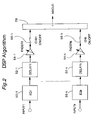
- the digital audio signals supplied from the AD converters 10 or from the digital input interface 16 are allotted to a plurality of input channels in the number of k, as shown by INPUT1 through INPUTk.
- Equalizers 50-1 through 50-k are provided for the respective signal processing channels (#1 through #k) to perform equalizing processing such as frequency characteristics modification on to the audio signals of the respective input channels.
- Delay blocks 52-1 through 52-k are to impart delay processing to the digital audio signals in the respective channels.
- Fader blocks 54-1 through 54-k are to adjust the levels of the audio signals in the respective channels in accordance with the actuation amounts of the respective fader controls on the control panel 6 (to be described in detail herein later).
- On/off switches 56-1 through 56-k are to select whether to output the audio signals of the respective channels or not individually.
- An adder 58 is to add or combine the audio signals from the respective processing channels and outputs the result MIXOUT. The output signal MIXOUT from the adder 58 is supplied to the DA converters 14 and the digital output interface 18.
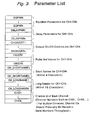
- EQPAR1 through EQPARk are equalizer parameters for setting the conditions in the equalizers 50-1 through 50-k, respectively.
- DELAYPAR1 through DELAYPARk are delay parameters for setting the respective delay times in the respective delay blocks 52-1 through 52-k.
- CHON/OFF1 through CHON/OFFk are channel output on/off control flags for determining the on/off states of the respective on/off switches 56-1 through 56-k in the respective signal processing channels.
- FADER1 through FADERk are Fader set values for determining the respective fader coefficients (signal levels) of the respective fader blocks 54-1 through 54-k.
- CH_SHORTNAME1 through CH_SHORTNAMEk are short names given to the respective signal processing channels #1 through #k and each consists of a character string with not more than four characters.
- CH_LONGNAME1 through CH_LONGNAMEk are long names given to the respective signal processing channels #1 through #k and each consists of a character string with not more than sixteen characters.
- CHID1 through CHIDk are channel identification number, and for example, the consecutive numbers "1" through "k” are given to the 1st through kth channels. In the case of multiple consoles connected together, the channel identification numbers CHIH1 through CHIDk are determined to be consecutive numbers throughout the entire channels.
- the mixing console of the present embodiment can be configured in multiple assemblies of a basic assembly consisting of eight signal processing channels, namely the number "k" of channels can be a multiple of "8".
- Fig. 6, therefore, shows the configuration of the control panel of such one assembly unit.
- Circular knobs 22-1 through 22-8 are attenuators which adjust the signal levels of the audio signals at the equalizers 50-1 through 50-k in the respective channels.
- Rectangular buttons 24-1 through 24-8 are toggle switches which change over from the "on” condition to the "off' condition and vice versa of the respective on/off switches 56-1 through 56-k, every time the button is pushed.
- Each switch button contains a lamp inside to indicate the "on” state and the "off' state of the switch by the lighting and the vanishing of the lamp, respectively.
- Rectangular buttons 26-1 through 26-8 are selection switches to exclusively select one of the channels of which the equalizer (one of 50-1 through 50-k) is subject to parameter setting. Namely, when any one of the selection switches 26-1 through 26-8 is actuated, only the actuated switch button is lit, extinguishing the other switch buttons. The actuated switch keeps the "on" condition until another switch button is depressed.
- control panel 6 further includes a sub-panel (not shown in Fig. 6) for adjusting various parameters to determine the characteristics of the equalizer 50-1 through 50-k so that the parameters of the equalizer (one of 50-1 through 50-k) of the channel of which the selection switch is on are ready to be set arbitrarily by the user.
- Indicator units 28-1 through 28-8 each are to display alphanumeric character strings each consisting of four or less characters.
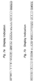
- the indicator units in combination, are available for displaying a complex indication for detailed information such as an indication of "a channel short name + a channel long name + a channel identification number" as shown in Figs. 7a and 7b according to the processing as will be described in detail herein later.
- Figs. 7a and 7b show two examples of complex indication using eight indicator units.
- the indicator unit 28-1 displays the channel short name
- the indicator unit 28-2 exhibits the symbol " ⁇ ”.
- the indicator units 28-3 through 28-6 show the channel long name consisting of up to sixteen characters
- the indicator unit 28-7 exhibits the symbol ">”.
- the indicator 28-8 displays the channel identification number.
- rectangular slide knobs 30-1 through 30-8 are fader controls, of each which the actuation amount determines the gain in the fader block 54-1 through 54-k (of Fig. 2).
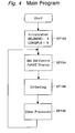
- the main program shown in Fig. 4 is started.
- the predetermined initialization processes take place.
- the selection switch number SELSWNO is set to be "0".
- the selection switch number SELSWNO is a variable representing a channel identification number (one of CHID1 through CHIDk) which is selected by a selection switch (one of 26-1 through 26-8), and a value "0" for this number means that none of the channels is selected.
- the long name display flag LONGFLG is also set to be "0".
- the long name display flag LONGFLG is set to be "1" in the case of a complex indication in which detailed information about one particular channel is displayed using the indicator units 28-1 through 28-8 for the eight signal processing channels as shown in Figs. 7a and 7b, while it is set to be "0" in the case of simple indications in which only a channel short name or a channel identification number is displayed for each one of the eight channels using each indicator unit allotted to each of the channels as shown in Fig. 6.
- a subprogram for selection switch control and name display (Fig. 5) is started. This subprogram is to renew the contents to be displayed by the respective indicator units 28-1 through 28-8 according to the actuated states of the selection switches 26-1 through 26-8.
- a step SP106 a channel setting process executed, wherein the gains of the respective faders 54-1 through 54-8 are set according to the actuated amounts of the respective slide knobs 30-1 through 30-8, and the on/off conditions of the respective on/off switches 56-1 through 56-8 are set according to the actuations of the respective toggle switches 24-1 through 24-8.
- the parameters for the equalizer block and the delay block of the channel under the selected condition are determined according to the actuated conditions in the parameter adjusting panel (not shown).
- the program further proceeds to a step SP108, other various necessary processes are conducted.
- the routine from the step SP104 through SP108 are repeated in the main program.
- This subprogram is invoked as a separate unit subprogram for every eight channels. For example, in the case of a mixing console having twenty-four channels, the subprogram executes three separate processes simultaneously. As the process moves forward to a step SP2 of Fig. 5, the operated conditions (on/off states) of the selection switches 26-1 through 26-8 are detected. And next at a step SP4, the variable "i" is set to be "1".
- a step SP6 judges whether there is an "on” event with respect to a selection switch 26-i (a selection switch 26-1 in the first cycle). More particularly, if the detection result at the step SP2 in the preceding run is "off' and the detection result at the step SP2 in the present run is "on”, the step SP6 judges that there is an "on” event. Assuming the case where there is an "on” event with the selection switch 26-1, the step SP6 judges "YES” and the process goes forward to a step SP8 to judge whether the selection switch number (variable SELSWNO) is other than the value "i".
- the selection switch number SELSWNO is set to be "0" at the initialization step SP102, the judgment at the step SP8 is "YES", and the process moves to a step SP10.
- the step SP10 substitutes "i" ("1" in the first cycle) for the selection switch number SELSWNO.
- the selection switch button 26-i i.e. 26-1 in this first cycle
- all other selection switch buttons are extinguished.
- step SP12 the process goes forward to a step SP12 to judge whether any of the selection switches 26-1 through 26-8 are in the "on" state.
- the judgment is "YES” and the processes moves forward to a step SP14.
- the step SP14 judges whether the long name display flag LONGFLAG is "0". As the long name display flag LONGFLAG is set to be "0" at the initialization step, the judgment here is "YES” and the process proceeds to a step SP16.
- the step SP12 judges "YES” and the process moves to the steps SP14 and SP16.
- the step SP16 judges "NO” without fail.
- the selection switch control/name display subprogram (Fig. 5) is invoked again while the selection switch 26-1 has been kept depressed longer than the predetermined duration T and the process comes to the step SP16 under the variable "i" set to be “1", the judgment here is now "YES”, and the process now goes to a step SP18.
- the step SP18 causes the indicator units 28-1 through 28-8 to display, for the variable "i" (which is now “1"), the short name CH_SHORTNAMEi, the long name CH_LONGNAMEi and the channel identification number CHIDi over the extended display area, that is, along the whole length of the eight indicator units as shown in Fig. 7a or 7b, as a complex indication of the information about the channel "i" (which is now “1").
- the process goes to a step SP20 to set the long name display flag LONGFLG to be "1".
- the processing proceeds through the steps SP14 and SP16 and skips to the step SP28, as long as the selection switch 26-1 is kept depressed, and thus no substantial processing is executed by the present subprogram (Fig. 5).
- the complex indication of the information consisting of the short name CH_SHORTNAMEi, the long name CH_LONGNAMEi and the channel identification number CHIDi about the channel "i" is displayed continuously for the variable "i" with which the step SP18 was executed for the last time.
- step SP12 judges "NO" and the process goes to a step SP22.
- the step SP22 sets the long name display flag LONGFLG to be "0".
- the channel short names CH_SHORTNAME1 through CH_SHORTNAME8 are displayed on the indicator units 28-1 through 28-8, respectively, as simple indications of the information about the respective channels.
- the displayed contents on the control panel are brought back to the initial state.
- the mixing console according to the present embodiment is capable of displaying a complex indication of the information about a channel which is designated by the user depressing the selection switch of the channel for longer than the predetermined duration T, the complex indication being an indication of the detailed information about the designated channel using the indicator units 28-1 through 28-8 for the eight channels.
- each of the indicator units 28-1 through 28-8 can employ display elements of a size of sufficient legibility (even though a few in number) to show details about the designated channel to the user.
- any one of the selection switches 26-1 through 26-8 is kept depressed for more than a predetermined period of time, this actuation determines the contents of the complex indication using the indicators 28-1 through 28-8 (at the step SP18), the displayed contents will not change as long as that depressed key is kept being depressed, even though any other selection switch is additionally depressed.
- a modification is possible in the subprogram so that a complex indication for the channel of the last depressed selection switch (even though momentarily) shall be displayed using the eight indicators 28-1 through 28-8, as long as any of the selection switch is kept being depressed.
- the detailed information about such channels as designated one after another can be confirmed by the complex indication, each in a short time.
- a further modification may be that the information contents to be displayed in a complex mode display such as the short name CH_SHORTNAMEi and the long name CH_LONGNAMEi should be arbitrarily inputted or set on the control panel 6 or by control elements or a computer connected externally. Further alternatively, various character strings or display patterns may be stored in a memory before hand, and any of such stored contents can be selected to be displayed.
- the present invention provides an information display device and method, and also a computer program therefor, in which a predetermined particular operation of a channel control element among a plurality of channel control elements causes a plurality of indicator units respectively for a plurality of channels, as a whole, to display detailed information about the channel of which the channel control element is operated in the particular operational manner.
- the present invention can present to the user the detailed information about an arbitrary channel without deteriorating the legibility or visibility of the characters on the indicator units.
Landscapes
- Engineering & Computer Science (AREA)
- Signal Processing (AREA)
- Circuit For Audible Band Transducer (AREA)
- Stereophonic System (AREA)
- Control Of Amplification And Gain Control (AREA)
- Tone Control, Compression And Expansion, Limiting Amplitude (AREA)
- Input From Keyboards Or The Like (AREA)
Applications Claiming Priority (2)
| Application Number | Priority Date | Filing Date | Title |
|---|---|---|---|
| JP2001203346A JP3620477B2 (ja) | 2001-07-04 | 2001-07-04 | 信号情報表示装置 |
| JP2001203346 | 2001-07-04 |
Publications (3)
| Publication Number | Publication Date |
|---|---|
| EP1276259A2 true EP1276259A2 (de) | 2003-01-15 |
| EP1276259A3 EP1276259A3 (de) | 2009-06-03 |
| EP1276259B1 EP1276259B1 (de) | 2010-09-01 |
Family
ID=19040002
Family Applications (1)
| Application Number | Title | Priority Date | Filing Date |
|---|---|---|---|
| EP02014547A Expired - Lifetime EP1276259B1 (de) | 2001-07-04 | 2002-07-01 | Vorrichtung, Verfahren und Rechnerprogramm zum Anzeigen von Signalverarbeitungsdaten |
Country Status (5)
| Country | Link |
|---|---|
| US (1) | US6985595B2 (de) |
| EP (1) | EP1276259B1 (de) |
| JP (1) | JP3620477B2 (de) |
| CN (2) | CN2691204Y (de) |
| DE (1) | DE60237494D1 (de) |
Families Citing this family (10)
| Publication number | Priority date | Publication date | Assignee | Title |
|---|---|---|---|---|
| JP3882190B2 (ja) * | 2002-07-15 | 2007-02-14 | ヤマハ株式会社 | レベル調整装置 |
| JP3800148B2 (ja) * | 2002-08-19 | 2006-07-26 | ヤマハ株式会社 | 信号処理装置およびその制御方法を実現するためのプログラム |
| US7319765B2 (en) * | 2002-09-06 | 2008-01-15 | Yamaha Corporation | Parameter setting device |
| US7145478B2 (en) * | 2002-12-17 | 2006-12-05 | Evolution Robotics, Inc. | Systems and methods for controlling a density of visual landmarks in a visual simultaneous localization and mapping system |
| US20040236297A1 (en) * | 2003-05-23 | 2004-11-25 | Drzewiecki Brian Michael | Thin, flexible sanitary napkin having a compression resistant absorbent structure |
| US7518055B2 (en) * | 2007-03-01 | 2009-04-14 | Zartarian Michael G | System and method for intelligent equalization |
| JP4254480B2 (ja) * | 2003-10-28 | 2009-04-15 | ヤマハ株式会社 | パラメータ表示方法、パラメータ表示装置およびプログラム |
| JP4884892B2 (ja) * | 2006-09-06 | 2012-02-29 | 株式会社タムラ製作所 | モニタスピーカ制御システム |
| EP2506464A1 (de) | 2011-03-30 | 2012-10-03 | Harman International Industries Ltd. | Audio-Verarbeitungsvorrichtung und Verfahren zur Ausgabe von Statusinformation |
| JP6236748B2 (ja) * | 2015-03-25 | 2017-11-29 | ヤマハ株式会社 | 音処理装置 |
Family Cites Families (7)
| Publication number | Priority date | Publication date | Assignee | Title |
|---|---|---|---|---|
| US5646362A (en) * | 1992-10-12 | 1997-07-08 | Yamaha Corporation | Sound parameter editing device for an electronic musical instrument |
| US5455602A (en) | 1993-03-29 | 1995-10-03 | Texas Instruments Incorporated | Combined modulation schemes for spatial light modulators |
| US5734731A (en) * | 1994-11-29 | 1998-03-31 | Marx; Elliot S. | Real time audio mixer |
| US5608807A (en) * | 1995-03-23 | 1997-03-04 | Brunelle; Thoedore M. | Audio mixer sound instrument I.D. panel |
| JP2937096B2 (ja) * | 1995-10-25 | 1999-08-23 | ヤマハ株式会社 | 楽音設定装置及び方法 |
| CA2261275A1 (en) * | 1996-06-24 | 1997-12-31 | Van Koevering Company | Musical instrument system |
| US7167763B2 (en) | 1997-09-24 | 2007-01-23 | Sony Corporation | Method and apparatus for providing a graphical user interface for a player/recorder system |
-
2001
- 2001-07-04 JP JP2001203346A patent/JP3620477B2/ja not_active Expired - Fee Related
-
2002
- 2002-07-01 EP EP02014547A patent/EP1276259B1/de not_active Expired - Lifetime
- 2002-07-01 DE DE60237494T patent/DE60237494D1/de not_active Expired - Lifetime
- 2002-07-02 CN CNU022409459U patent/CN2691204Y/zh not_active Expired - Fee Related
- 2002-07-02 US US10/189,317 patent/US6985595B2/en not_active Expired - Lifetime
- 2002-07-02 CN CN02141206.5A patent/CN1227895C/zh not_active Expired - Fee Related
Also Published As
| Publication number | Publication date |
|---|---|
| JP2003018111A (ja) | 2003-01-17 |
| CN1227895C (zh) | 2005-11-16 |
| CN1395446A (zh) | 2003-02-05 |
| EP1276259A3 (de) | 2009-06-03 |
| CN2691204Y (zh) | 2005-04-06 |
| DE60237494D1 (de) | 2010-10-14 |
| HK1050457A1 (en) | 2003-06-20 |
| EP1276259B1 (de) | 2010-09-01 |
| JP3620477B2 (ja) | 2005-02-16 |
| US20030007652A1 (en) | 2003-01-09 |
| US6985595B2 (en) | 2006-01-10 |
Similar Documents
| Publication | Publication Date | Title |
|---|---|---|
| US10425054B2 (en) | Operation panel structure and control method and control apparatus for mixing system | |
| US8312375B2 (en) | Digital mixer | |
| JP4321259B2 (ja) | ミキサ装置およびミキサ装置の制御方法 | |
| US8050426B2 (en) | Digital mixer apparatus and editing method therefor | |
| US4628789A (en) | Tone effect imparting device | |
| US7694230B2 (en) | Digital mixer and program | |
| EP1276259B1 (de) | Vorrichtung, Verfahren und Rechnerprogramm zum Anzeigen von Signalverarbeitungsdaten | |
| US7689307B2 (en) | Digital audio mixer | |
| JP4023328B2 (ja) | ミキシングシステムおよびプログラム | |
| EP2278736A2 (de) | Digitalmischer | |
| US8064621B2 (en) | Digital mixer | |
| EP1530197B1 (de) | Verfahren und Programm zur Steuerung eines Parameters und Vorrichtung zum Einstellen eines Parameters | |
| EP2259458A2 (de) | Audiovorrichtung und Verfahren zur Einstellung der Anzahl der Busse in einer Audiovorrichtung | |
| JP4066254B2 (ja) | ディジタルミキサ | |
| US7697703B2 (en) | Digital mixer apparatus | |
| JP4036110B2 (ja) | ミキシングシステムおよびプログラム | |
| JP4107250B2 (ja) | ミキシング装置 | |
| JP4066253B2 (ja) | ディジタルミキサ | |
| JP2007074624A (ja) | デジタルミキサおよびプログラム | |
| JPH03266892A (ja) | 楽音制御パラメータ設定装置 | |
| JP2522081C (de) |
Legal Events
| Date | Code | Title | Description |
|---|---|---|---|
| PUAI | Public reference made under article 153(3) epc to a published international application that has entered the european phase |
Free format text: ORIGINAL CODE: 0009012 |
|
| 17P | Request for examination filed |
Effective date: 20020701 |
|
| AK | Designated contracting states |
Kind code of ref document: A2 Designated state(s): AT BE BG CH CY CZ DE DK EE ES FI FR GB GR IE IT LI LU MC NL PT SE SK TR |
|
| AX | Request for extension of the european patent |
Free format text: AL;LT;LV;MK;RO;SI |
|
| RAP1 | Party data changed (applicant data changed or rights of an application transferred) |
Owner name: YAMAHA CORPORATION |
|
| PUAL | Search report despatched |
Free format text: ORIGINAL CODE: 0009013 |
|
| AK | Designated contracting states |
Kind code of ref document: A3 Designated state(s): AT BE BG CH CY CZ DE DK EE ES FI FR GB GR IE IT LI LU MC NL PT SE SK TR |
|
| AX | Request for extension of the european patent |
Extension state: AL LT LV MK RO SI |
|
| AKX | Designation fees paid |
Designated state(s): DE FR GB IT |
|
| GRAP | Despatch of communication of intention to grant a patent |
Free format text: ORIGINAL CODE: EPIDOSNIGR1 |
|
| RIC1 | Information provided on ipc code assigned before grant |
Ipc: H04H 60/04 20080101AFI20100601BHEP |
|
| GRAS | Grant fee paid |
Free format text: ORIGINAL CODE: EPIDOSNIGR3 |
|
| GRAA | (expected) grant |
Free format text: ORIGINAL CODE: 0009210 |
|
| AK | Designated contracting states |
Kind code of ref document: B1 Designated state(s): DE FR GB IT |
|
| REG | Reference to a national code |
Ref country code: GB Ref legal event code: FG4D |
|
| REF | Corresponds to: |
Ref document number: 60237494 Country of ref document: DE Date of ref document: 20101014 Kind code of ref document: P |
|
| PG25 | Lapsed in a contracting state [announced via postgrant information from national office to epo] |
Ref country code: IT Free format text: LAPSE BECAUSE OF FAILURE TO SUBMIT A TRANSLATION OF THE DESCRIPTION OR TO PAY THE FEE WITHIN THE PRESCRIBED TIME-LIMIT Effective date: 20100901 |
|
| PLBE | No opposition filed within time limit |
Free format text: ORIGINAL CODE: 0009261 |
|
| STAA | Information on the status of an ep patent application or granted ep patent |
Free format text: STATUS: NO OPPOSITION FILED WITHIN TIME LIMIT |
|
| 26N | No opposition filed |
Effective date: 20110606 |
|
| REG | Reference to a national code |
Ref country code: DE Ref legal event code: R097 Ref document number: 60237494 Country of ref document: DE Effective date: 20110606 |
|
| PGFP | Annual fee paid to national office [announced via postgrant information from national office to epo] |
Ref country code: GB Payment date: 20140625 Year of fee payment: 13 |
|
| PGFP | Annual fee paid to national office [announced via postgrant information from national office to epo] |
Ref country code: FR Payment date: 20140708 Year of fee payment: 13 |
|
| PGFP | Annual fee paid to national office [announced via postgrant information from national office to epo] |
Ref country code: DE Payment date: 20150624 Year of fee payment: 14 |
|
| GBPC | Gb: european patent ceased through non-payment of renewal fee |
Effective date: 20150701 |
|
| PG25 | Lapsed in a contracting state [announced via postgrant information from national office to epo] |
Ref country code: GB Free format text: LAPSE BECAUSE OF NON-PAYMENT OF DUE FEES Effective date: 20150701 |
|
| REG | Reference to a national code |
Ref country code: FR Ref legal event code: ST Effective date: 20160331 |
|
| PG25 | Lapsed in a contracting state [announced via postgrant information from national office to epo] |
Ref country code: FR Free format text: LAPSE BECAUSE OF NON-PAYMENT OF DUE FEES Effective date: 20150731 |
|
| REG | Reference to a national code |
Ref country code: DE Ref legal event code: R119 Ref document number: 60237494 Country of ref document: DE |
|
| PG25 | Lapsed in a contracting state [announced via postgrant information from national office to epo] |
Ref country code: DE Free format text: LAPSE BECAUSE OF NON-PAYMENT OF DUE FEES Effective date: 20170201 |