EP1276260A2 - Dispositif de delai differentiel de signal, recepteur et système de communication utilisant ce dispositif - Google Patents
Dispositif de delai differentiel de signal, recepteur et système de communication utilisant ce dispositif Download PDFInfo
- Publication number
- EP1276260A2 EP1276260A2 EP02012478A EP02012478A EP1276260A2 EP 1276260 A2 EP1276260 A2 EP 1276260A2 EP 02012478 A EP02012478 A EP 02012478A EP 02012478 A EP02012478 A EP 02012478A EP 1276260 A2 EP1276260 A2 EP 1276260A2
- Authority
- EP
- European Patent Office
- Prior art keywords
- delay
- signal
- differential signal
- error
- delaying
- Prior art date
- Legal status (The legal status is an assumption and is not a legal conclusion. Google has not performed a legal analysis and makes no representation as to the accuracy of the status listed.)
- Withdrawn
Links
Images


Classifications
-
- H—ELECTRICITY
- H04—ELECTRIC COMMUNICATION TECHNIQUE
- H04J—MULTIPLEX COMMUNICATION
- H04J3/00—Time-division multiplex systems
- H04J3/02—Details
- H04J3/04—Distributors combined with modulators or demodulators
- H04J3/047—Distributors with transistors or integrated circuits
-
- H—ELECTRICITY
- H03—ELECTRONIC CIRCUITRY
- H03K—PULSE TECHNIQUE
- H03K5/00—Manipulating of pulses not covered by one of the other main groups of this subclass
- H03K5/13—Arrangements having a single output and transforming input signals into pulses delivered at desired time intervals
-
- H—ELECTRICITY
- H03—ELECTRONIC CIRCUITRY
- H03L—AUTOMATIC CONTROL, STARTING, SYNCHRONISATION OR STABILISATION OF GENERATORS OF ELECTRONIC OSCILLATIONS OR PULSES
- H03L7/00—Automatic control of frequency or phase; Synchronisation
-
- H—ELECTRICITY
- H04—ELECTRIC COMMUNICATION TECHNIQUE
- H04N—PICTORIAL COMMUNICATION, e.g. TELEVISION
- H04N7/00—Television systems
- H04N7/10—Adaptations for transmission by electrical cable
- H04N7/108—Adaptations for transmission by electrical cable the cable being constituted by a pair of wires
-
- H—ELECTRICITY
- H04—ELECTRIC COMMUNICATION TECHNIQUE
- H04J—MULTIPLEX COMMUNICATION
- H04J3/00—Time-division multiplex systems
- H04J3/02—Details
- H04J3/06—Synchronising arrangements
- H04J3/0635—Clock or time synchronisation in a network
- H04J3/0685—Clock or time synchronisation in a node; Intranode synchronisation
Definitions
- This invention relates to a differential signal-delaying apparatus for delaying a received differential signal in data transmission through a differential signal, and an art related thereto.
- DVI specification Digital Visual Interface Revision 1.0
- http://www.ddwg.org/ has heretofore been established as a standard of an art for transmitting digital video data at high speeds through a differential signal.
- Fig. 7 is a block diagram, illustrating a prior art receiver constructed according to the DIV specification. As illustrated in Fig. 7, the receiver includes a differential-amplifying unit 10, a serial/parallel-converting unit (or a S/P-converting unit) 11, and an 8B10B decoder 12.
- the receiver includes a differential-amplifying unit 10, a serial/parallel-converting unit (or a S/P-converting unit) 11, and an 8B10B decoder 12.
- the differential-amplifying unit 10 receives a differential signal that is sent from a transmitter (not shown) through a pair cable.
- the differential signal includes one signal X1 and another X2, each of which is a serial signal and 10-bit redundant code.
- the differential-amplifying unit 10 generates signal "Z" according to a potential difference between signals X1, X2.
- the S/P-converting unit 11 converts signal Z (a serial signal) from the differential-amplifying unit 11 into a parallel signal.
- the 8B10B decoder 12 decodes the parallel signal (a 10-bit redundant code) from the S/P-converting unit 11, and then provides the decoded signal as 8-bit parallel data.
- Fig. 8 is an illustration, showing timing in order to describe how adversely the differential signal skew affects.
- Fig. 8 (a) is a descriptive illustration, showing the screw.
- Fig. 8 (b) illustrates an eye pattern (an overwritten waveform) of output signal "Z" from the differential-amplifying unit 10 in the presence of the differential signal skew.
- Fig. 8 (c) illustrates another eye pattern (an overwritten waveform) of the same output signal "Z" but in the absence of the skew.
- arrival time difference "T” occurs between one signal X1 and another X2, both of which form a differential signal to be fed into the differential-amplifying unit 10.
- differential signal skew refers to an "intra-pair-skew” as discussed in the DVI specification, but differs from an “inter-pair-skew” as given in the same DVI specification.
- a vide-transmitting system typically employs a pair cable having a length ranging from 2 to 5 meters. In the future, the vide-transmitting system is expected to use a longer pair cable.
- a prior art digital variable delay circuit is disclosed in published Japanese Patent Application Laid-Open No. 4-227313.
- the digital variable delay circuit delays an entered differential signal for output thereof. At that time, delay time is adjusted by the adjustment of a value of a current from a variable electrical current source.
- a purpose of the digital variable delay circuit is to merely control the delay time, not to suppress the differential signal skew-caused errors. Consequently, the circuit as described above is free of countermeasures to suppress such the errors.
- an object of the present invention is to provide a differential signal-delaying apparatus capable of inhibiting the occurrence of differential signal skew-caused errors to the utmost regardless of whether or not a pair cable for transmitting a differential signal is great in length, and further to provide an art related thereto.
- a first aspect of the present invention provides a differential signal-delaying apparatus comprising a first delay unit for delaying a first signal of an entered differential signal in order to generate a first delay signal, a second delay unit for delaying a second signal of the entered differential signal in order to generate a second delay signal, an error-detecting unit for generating an error signal when detecting an error in a signal that is based on the first and second delay signals, a counting unit for counting the number of times of errors per predetermined time upon receipt of the error signal, and a delay control unit for varying a delay time difference that is a difference between respective delay times in the first and second delay unit, wherein the counting unit counts the number of times of errors per predetermined time for each change in delay time difference to be made by the delay control unit, while the delay control unit sets the respective delay times in the first and second delay unit to respective delay times that determine a delay time difference in which the number of times of errors per predetermined time is minimized.
- the above-structured differential signal-delaying apparatus practices the above delay time-setting operation including the step of locating the delay time difference in which the number of times of errors per predetermined time is minimized, and thereby provides a minimized differential signal skew.
- the occurrence of differential signal skew-caused errors is inhibited to an extreme extent. This beneficial effect is provided regardless of whether or not a pair cable for use in feeding the differential signal is large in length.
- the delay control unit starts changing the delay time difference either when the differential signal-delaying apparatus is switched on or when a pair cable for use in entering the differential signal is inserted. Then, the delay control unit sets the respective delay times in the first and second delay unit to respective delay times that determine a delay time difference in which the number of times of errors per predetermined time is minimized.
- the above-structured differential signal-delaying apparatus ensures that the delay time difference in which the number of times of errors per predetermined time is minimized is located when there is a possibility of pair cable replacement. As a result, the differential signal-delaying apparatus is able to handle a possible change in differential signal skew.
- the delay control unit deactivates the error-detecting unit and the counting unit when setting the respective delay times in the first and second delay unit.
- the above-structured differential signal-delaying apparatus reduces power consumption.
- a fourth aspect of the invention provides a differential signal-delaying apparatus comprising a first delay unit for delaying a first signal of an entered differential signal in order to generate a first delay signal, a second delay unit for delaying a second signal of the entered differential signal in order to generate a second delay signal, an error-detecting unit for detecting an error in a signal that is based on the first and second delay signals, and a delay control unit for varying a delay time difference that is a difference between respective delay times in the first and second delay unit, wherein the error-detecting unit detects the error for each change in delay time difference to be made by the delay control unit, while the delay control unit sets the respective delay times in the first and second delay unit to respective delay times that determine a delay time difference in which no error is detected.
- the above-constructed differential signal-delaying apparatus practices the above delay time-setting operation including the step of locating the delay time difference in which no error is detected, and thereby provides a minimized differential signal skew.
- the occurrence of differential signal skew-caused errors is suppressed to the greatest degree.
- This beneficial effect is provided regardless of whether or not a pair cable for use in feeding the differential signal is large in length.
- the differential signal-delaying apparatus as discussed above eliminates a counter for counting the number of times of errors, and such a simpler construction is able to achieve the above beneficial effect.
- the delay control unit starts changing the delay time difference either when the differential signal-delaying apparatus is switched on or when a pair cable for use in entering the differential signal is inserted. Then, the delay control unit sets the respective delay times in the first and second delay unit to respective delay times that determine a delay time difference in which no error is detected.
- the above-constructed differential signal-delaying apparatus ensures that the delay time difference in which no error is detected is located when there is a likelihood of pair cable replacement. As a result, the differential signal-delaying apparatus is able to handle a possible change in differential signal skew.
- the delay control unit deactivates the error-detecting unit when setting the respective delay times in the first and second delay unit.
- the above construction reduces power consumption.
- the delay control unit varies the delay time difference by controlling the respective delay times in the first and second delay unit by means of first and second control signals to be fed into the first and second delay unit, respectively, wherein the delay time in the first delay unit is linearly varied with a voltage of the first control signal, while the delay time in the second delay unit is linearly varied with a voltage of the second control signal.
- the above-structured differential signal-delaying apparatus provides easy control over the delay time difference.
- An eighth aspect of the present invention provides a receiver for receiving a differential signal that includes first and second signals, each of which is a serial signal, comprising a differential signal-delaying unit for delaying the first and second signals of the differential signal in order to provide the delayed first and second signals as first and second delay signals, respectively, a differential-amplifying unit for generating an output signal according to a potential difference between the first and second delay signals, a serial/parallel-converting unit for converting the output signal into a parallel signal, which output signal is a serial signal sent out from the differential-amplifying unit, and a decoder for decoding the parallel signal from the serial/parallel-converting unit, the differential signal-delaying unit comprising a first delay unit for delaying the first signal of the differential signal in order to generate the first delay signal, a second delay unit for delaying the second signal of the differential signal in order to produce the second delay signal, an error-detecting unit for generating an error signal when detecting an error in the parallel signal from the serial/parallel-converting unit,
- the above-structured differential signal-delaying unit having the above construction practices the above delay time-setting operation including the step of locating the delay time difference in which the number of times of errors per predetermined time is minimized, and thereby provides a minimized differential signal skew.
- the occurrence of differential signal skew-caused errors is suppressed to the utmost. This beneficial effect is achievable regardless of whether or not a pair cable for use in receiving the differential signal is great in length.
- the delay control unit starts changing the delay time difference either when the receiver is switched on or when a pair cable for use in feeding the differential signal is inserted into the receiver, and then the delay control unit sets the respective delay times in the first and second delay unit to respective delay times that determine a delay time difference in which the number of times of errors per predetermined time is minimized.
- the above-constructed differential signal-delaying unit ensures that the delay time difference in which the number of times of errors per predetermined time is minimized is located when there is a likelihood of pair cable replacement. As a result, the differential signal-delaying unit is able to take care of a possible change in the differential signal skew.
- the delay control unit deactivates the error-detecting unit and the counting unit when setting the respective delay times in the first and second delay unit.
- This construction reduces power consumption.
- An eleventh aspect of the present invention provides a receiver for receiving a differential signal that includes first and second signals, each of which is a serial signal, comprising a differential signal-delaying unit for delaying the first and second signals of the differential signal in order to provide the delayed first and second signals as first and second delay signals, respectively, a differential-amplifying unit for generating an output signal according to a potential difference between the first and second delay signals, a serial/parallel-converting unit for converting the output signal into a parallel signal, which output signal is a serial signal sent out from the differential-amplifying unit, and a decoder for decoding the parallel signal from the serial/parallel-converting unit, the differential signal-delaying unit comprising a first delay unit for delaying the first signal of the differential signal in order to generate the first delay signal, a second delay unit for delaying the second signal of the differential signal in order to produce the second delay signal, an error-detecting unit for detecting an error in the parallel signal from the serial/parallel-converting unit, and a delay control
- the above-structured differential signal-delaying unit practices the above delay time-setting operation including the step of locating the delay time difference in which no error is detected, and thereby provides a minimized differential signal skew.
- the occurrence of differential signal skew-caused errors is suppressed to an extreme extent.
- This beneficial effect is achievable regardless of whether or not a pair cable for use in receiving the differential signal is great in length.
- the differential signal-delaying unit as discussed above is free of a counter for counting the number of times of errors, and such a simpler construction is able to achieve the above beneficial effect.
- the delay control unit starts changing the delay time difference either when the receiver is switched on or when a pair cable for use in feeding the differential signal is inserted into the receiver, and then the delay control unit sets the respective delay times in the first and second delay unit to respective delay times that determine a delay time difference in which no error is detected.
- the above-constructed differential signal-delaying unit ensures that the delay time difference in which no error is detected is located when there is a possibility of pair cable replacement. As a result, the differential signal-delaying unit is able to take care of a possible change in a differential signal skew.
- the delay control unit deactivates the error-detecting unit when setting the respective delay times in the first and second delay unit.
- This construction reduces power consumption.
- the receiver receives the differential signal that includes first and second signals, each of which is a 10-bit redundant code, while the decoder decodes the parallel signal from the serial/parallel-converting unit, which parallel signal is the 10-bit redundant code, and thereby provides the decoded parallel signal as 8-bit parallel data.
- the above-constructed receiver is possible to handle a redundant code produced by means of an encoding algorithm according to the DVI specification.
- the delay control unit varies the delay time difference by controlling the respective delay times in the first and second delay unit by means of first and second control signals to be entered into the first and second delay unit, respectively.
- the delay time in the first delay unit is linearly varied with a voltage of the first control signal
- the delay time in the second delay unit is linearly varied with a voltage of the second control signal.
- the above-structured delay control unit realizes easy control over the delay time difference.
- a sixteenth aspect of the present invention provides a communication system including a transmitter and a receiver, which are communicated with one another through a pair cable, the receiver receiving a differential signal from the transmitter, the receiver comprising a differential signal-delaying unit for delaying the differential signal, the differential signal-delaying unit comprising a first delay unit for delaying a first signal of the differential signal in order to generate a first delay signal, a second delay unit for delaying a second signal of the differential signal in order to generate a second delay signal, an error-detecting unit for generating an error signal when detecting an error in a signal that is based on the first and second delay signals, a counting unit for counting the number of times of errors per predetermined time upon receipt of the error signal, and a delay control unit for varying a delay time difference that is a difference between respective delay times in the first and second delay unit, wherein the counting unit counts the number of times of errors per predetermined time for each change in delay time difference to be made by the delay control unit, while the delay control unit sets the respective delay times
- the above-structured differential signal-delaying unit practices the above delay time-setting operation including the step of locating the delay time difference in which the number of times of errors per predetermined time is minimized, and thereby provides a minimized differential signal skew.
- the occurrence of differential signal skew-caused errors is suppressed to an extreme extent. This beneficial effect is achievable regardless of whether or not a pair cable for use in transmitting the differential signal is large in length.
- a seventeenth aspect of the present invention provides a communication system including a transmitter and a receiver, which are communicated with one another through a pair cable, the receiver receiving a differential signal from the transmitter, the receiver comprising a differential signal-delaying unit for delaying the differential signal, the differential signal-delaying unit comprising a first delay unit for delaying a first signal of the differential signal in order to generate a first delay signal, a second delay unit for delaying a second signal of the differential signal in order to generate a second delay signal, an error-detecting unit for detecting an error in a signal that is based on the first and second delay signals, and a delay control unit for varying a delay time difference that is a difference between respective delay times in the first and second delay unit, wherein the error-detecting unit detects the error for each change in delay time difference to be made by the delay control unit, while the delay control unit sets the respective delay times in the first and second delay unit to respective delay times that determine a delay time difference in which no error is detected.
- the above-structured differential signal-delaying unit practices the above delay time-setting operation including the step of locating the delay time difference in which no error is detected, and thereby provides a minimized differential signal skew.
- the occurrence of differential signal skew-caused errors is inhibited to the largest extent.
- This beneficial effect is achievable regardless of whether or not a pair cable for use in transmitting the differential signal is large in length.
- the differential signal-delaying unit as discussed above is free of a counter for counting the number of times of errors, and such a simper structure is able to achieve the beneficial effect.
- Fig. 1 is a block diagram, illustrating a communication system according to a first embodiment of the present invention.
- the communication system includes a transmitter 1 and a receiver 2.
- a pair cable 3 interconnects the transmitter 1 and the receiver 2.
- the receiver 2 includes a differential signal-delaying unit 4, a differential-amplifying unit 5, a serial/parallel-converting unit (S/P-converting unit) 6, and a decoder 7.
- the transmitter 1 encodes display information, e.g., a video signal, thereby producing a redundant code.
- the transmitter 1 generates differential signal "S1" according to the resulting redundant code, and then sends differential signal S 1 to the receiver 2 through the pair cable 3.
- transmitter 1 and receiver 2 are replaced by, e.g., a set-top box (STB) and a television, respectively.
- STB set-top box
- Differential signal S1 includes one signal X1 and another X2, which are serial signals and which are opposite in polarity to one another.
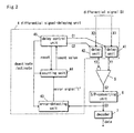
- Fig. 2 is a block diagram, illustrating the receiver 2 of Fig. 1.
- Fig. 2 the same components as those of Fig. 1 are identified by the same reference characters.
- the differential signal-delaying unit 4 includes a pair of delay unit 41, 42, an error-detecting unit 43, a counting unit 44, and a delay control unit 45.
- the pair of delay unit 41, 42 will initially be discussed about behavior thereof.
- One signal X1 is fed into the delay unit 41.
- the delay unit 41 delays the fed signal X1 in accordance with control signal C1 from the delay control unit 45, and then provides the delayed signal X1 as delay signal Y1.
- Another signal X2 is entered into the delay unit 42.
- the delay unit 42 delays the fed signal X2 in accordance with control signal C2 from the delay control unit 45, and then provides the delayed signal X2 as delay signal Y2.
- Fig. 3 is a descriptive illustration, showing details of behavior provided by the delay unit 41 of Fig. 2.
- Fig. 3 (a) is an illustration, showing how the signals enter and leave the delay unit 41.
- Fig. 3 (b) is a descriptive illustration, showing delay time in the delay unit 41.
- Fig. 3 (c) is a graph, illustrating a relationship between a voltage (V) of control signal C1 to be sent to the delay unit 41 and the delay time (psec) in the delay unit 41.
- Fig. 3 (d) is a table, illustrating a relationship between the voltage (V) of control signal C1 and the delay time (psec) in the delay unit 41.
- the delay unit 41 delays the entered signal X1 by an amount of delay time ⁇ in accordance with control signal C1, and then provides the delayed signal X1 as delay signal Y1.
- delay time ⁇ in the delay unit 41 is linearly varied with the voltage of control signal C1.
- a delay time in the delay unit 42 is linearly varied with a voltage of control signal C2 that is sent from the delay control unit 45, and assumes characteristics as illustrated in Figs. 3 (c), 3 (d).
- the delay unit 41 feeds delay signal Y1 into the differential-amplifying unit 5 at one terminal thereof.
- the delay unit 42 enters delay signal Y2 into the differential-amplifying unit 5 at another terminal thereof.
- the differential-amplifying unit 5 generates output signal "S2" according to a potential difference between respective delay signals Y1 and Y2.
- the differential-amplifying unit 5 enters signal S2 (a serial signal) into the serial/parallel-converting unit 6, in which signal S2 (the serial signal) is converted into parallel signal S3.
- the serial/parallel-converting unit 6 feeds parallel signal S3 (a redundant code) into the decoder 7.
- the decoder 7 decodes parallel signal S3 into original data, thereby providing the decoded original data.
- the serial/parallel-converting unit 6 feeds parallel signal S3 (the redundant code) into the error-detecting unit 43.
- the error-detecting unit 43 detects an error in parallel signal S3, and sends out error signal "E" to the counting unit 44 upon detection of the error.
- the counting unit 44 counts the number of times of errors that occur within a predetermined time, upon receipt of error signal "E" that is sent from the error-detecting unit 43 each time when the error-detecting unit 43 detects the error in parallel signal S3.
- the counting unit 44 sends out information (a count value) on the counted times of errors per predetermined time to the delay control unit 45.
- the counting unit 44 has a maximum countable value set therein, and functions to stop counting when counting up to the maximum value.
- the counting unit 44 is provided with an overflow-preventing function.
- the overflow function prevents malfunction of the counting unit 44.
- the differential signal-delaying unit 4 including the delay control unit 45 assumes adjustment and fixed modes.
- delay control unit 45 behaves when the differential signal-delaying unit 4 is in the adjustment mode.
- the delay control unit 45 controls respective voltages of control signals C1, C2 to be directed to the delay unit 41, 42, respectively.
- Such voltage control varies respective delay times in the delay unit 41, 42 in such a manner that a difference (hereinafter called a delay time difference) between the respective delay times in the delay unit 41, 42 is varied at certain time intervals.
- Such a change in delay time difference to be made by the delay control unit 45 refers to respective variations in output timing of delay signal Y1 and that of delay signal Y2.
- the counting unit 44 For each change in delay time difference to be made by the delay control unit 45, the counting unit 44 counts the number of times of errors that occur within a predetermined time, and then sends out a count value to the delay control unit 45.
- the delay control unit 45 sets the respective delay times in the delay unit 41, 42 to respective delay times that determine a delay time difference in which the number of times of errors per predetermined time is minimized.
- the delay control unit 45 sets the respective voltages of control signals C1, C2 to respective voltages in which the number of times of errors per predetermined time is minimized.
- the delay control unit 45 deactivates the error-detecting unit 43 and counting unit 44 after setting the respective voltages of control signals C1, C2, and the differential signal-delaying unit 4 is put into a fixed mode. As a result, reduced power consumption in the fixed mode is achievable.
- the delay control unit 45 resets the count value in the counting unit 44 to zero for each change in delay time difference, while the counting unit 44 counts the number of times of errors per predetermined time for each change in delay time difference.
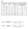
- Fig. 4 is a descriptive illustration, showing behavior of the delay control unit 45 in the adjustment mode.
- Fig. 4 illustrates a relationship between respective voltages of control signal C1, C2 and a delay time difference when a relationship between the voltage of control signal C1 (or control signal C2) and a delay time in the delay unit 41 (or delay unit 42) is established in a manner as illustrated in Figs. 3 (c) and 3 (d).
- the delay time difference is 30 (psec) when control signals C1, C2 have respective voltages of 4 (V) and 1 (V).
- the delay time different is yielded by: the delay time in the delay unit 41 minus that in the delay unit 42.
- the delay control unit 45 varies the respective voltages of control signals C1, C2 in order to vary the delay time difference at certain time intervals, i.e., at 10-psec intervals.
- the counting unit 44 counts the number of times of errors per predetermined time for each change in delay time difference to be made by the delay control unit 45, and then sends out a count value to the delay control unit 45.
- the delay control unit 45 sets the respective voltages of control signals C1, C2 to 2 (V) and 1 (V), respectively, because 2 (V) and 1 (V) are voltages that are determined when the delay time difference is 10 (psec).
- the differential signal-delaying unit 4 is thereafter gone into a fixed mode.
- the delay control unit 45 varies the delay time difference between the delay signals Y1, Y2.
- Such a variation in delay time difference refers to variations in difference in time in which delay signals Y1, Y2 arrive the differential-amplifying unit 5.
- Such a difference in delay signal arrival time is what is called a differential signal skew.
- the differential signal skew is varied with a change in delay time difference to be made by the delay control unit 45.
- the differential signal skew brings about errors whose number of times of the occurrence per predetermined time varies with a change in delay time difference. It can further be thought that a greater number of times of errors per predetermined time increase the differential signal skew, while a smaller number of times of errors per predetermined time decrease the differential signal skew.
- the delay control unit 45 sets the respective delay times in the delay unit 41, 42 to a delay time difference in which the number of times of errors per predetermined time is minimized, i.e., a delay time difference in which the differential signal skew is minimized.
- the above delay time-setting operation including the step of locating the delay time difference in which the number of times of errors per predetermined time is minimized provides a minimized differential signal skew. As a result, the occurrence of differential signal skew-caused errors is inhibited to the utmost.
- the above beneficial effect is achievable regardless of whether or not the pair cable 3 is large in length. More specifically, although the differential signal-delaying unit 4 is thought to receive a differential signal with a greater skew through a longer pair cable 3 than through a shorter one, the above beneficial effect is provided irrespective of how large the skew is when the differential signal-delaying unit 4 receives the differential signal.
- the delay control unit 45 continues to generate control signals C1, C2 after setting the respective voltages thereof to respective voltages in which the number of times of errors per predetermined time is minimized.
- the delay control unit 45 continues to generate control signals C1, C2 after setting the voltages thereof to 2 (V) and 1 (V), respectively, in which the number of times of errors per predetermined time is minimized.
- the delay control unit 45 actuates the error-detecting unit 43 and the counting unit 44, and the differential signal-delaying unit 4 is put into the adjustment mode.
- the differential signal-delaying unit 4 is brought back into the adjustment mode in response to a likelihood of pair cable replacement, even after the differential signal-delaying unit 4 is set into the fixed mode from the adjustment mode.
- the pair cable replacement changes the differential signal skew, and the difference signal skew must be minimized by the above delay time-setting operation that includes the step of locating the delay time difference again in which the number of times of errors per predetermined time is minimized, in order to suppress the occurrence of differential signal skew-caused errors to the utmost.
- the delay time difference is controllable with ease when the respective delay times in the delay unit 41, 42 are linearly varied with the respective voltages of control signals C1, C2, respectively, as illustrated in Figs. 3 (c) and 3 (d).
- Fig. 5 is a descriptive illustration, showing operations of the present embodiment.
- Fig. 5 (a) illustrates an eye pattern (an overwritten waveform) of signal S2 sent from the differential-amplifying unit 5 when the differential signal-delaying unit 4 is in the adjustment mode.
- the shown signal S2 is generated when a differential signal skew is large, not when the number of times of errors per predetermined time is minimized.
- signal S2 has several waveforms (a waveform for each delay time difference).
- Fig.5(a) illustrates one of such waveforms, which includes a large-sized skew.
- Fig. 5 (b) illustrates an eye pattern (an overwritten waveform) of signal S2 sent from the differential-amplifying unit 5 when the differential signal-delaying unit 4 is in the fixed mode.
- the shown signal S2 is generated when the number of times of errors per predetermined time is minimized, or rather when the differential signal skew is minimized.
- the eye pattern of signal S2 in the fixed mode is greater in openness in the direction of time lapse than that in the adjustment mode (Fig. 5 (a)).
- data is set to be 0 (zero) or otherwise 1 (one) at longer time intervals in the fixed mode that sets the respective delay times in the delay unit 41, 42 to a delay time difference in which the number of times of errors per predetermined time is minimized.
- a data value is decided as either 0 (zero) or 1 (one) with improved certainty, and the occurrence of the difference signal skew-caused errors is inhibited to an extreme extent.
- the transmitter 1, serial/parallel-converting unit 6, and decoder 1 as illustrated in Fig. 1 and the error-detecting unit 43 of Fig. 2 are constructed in a manner described below.
- the remaining components are constructed in a manner discussed above.
- the transmitter 1 encodes original 8-bit data (e.g., a 8-bit video signal), thereby producing a 10-bit redundant code including 2-bit redundant bit (hereinafter called a 8B10B code). Such encoding is practiced according to an algorithm that conforms to the DVI specification. The other aspects of the transmitter 1 are similar to those previously described.
- the differential-amplifying unit 5 feeds signal S2 (a 10-bit serial signal) to the serial/parallel-converting unit 6, in which signal S2 is converted into 10-bit parallel signal S3.
- the serial/parallel-converting unit 6 enters parallel signal S3 (the 8B10B code) into decoder 7.
- the decoder 7 decodes parallel signal S3 into original 8-bit parallel data, thereby providing the decoded data.
- Such decoding is practiced according to an algorithm that conforms to the DVI specification.
- the serial/parallel-converting unit 6 feeds parallel signal S3 (the 8B10B code) into the error-detecting unit 43.
- the error-detecting unit 43 detects an error in parallel signal S3. Upon detection of the error, the error-detecting unit 43 sends out error signal "E" to the counting unit 44.
- the error-detecting unit 43 detects a word from the 8B10B code that is fed from the serial/parallel-converting unit 6, which word is absent in an 8B10B code word list (a word list in which the original 8-bit data is provided when the 8B10B code is decoded). Upon detection of the word, the error-detecting unit 43 sends out the error signal to the counting unit 44.
- the error-detecting unit 43 is achievable by means of ROM (a read-only memory) having a 10-bit input width in order to feed 10-bit parallel signal S3 into the error-detecting unit 43 and further having a 1-bit output width in order to generate error signal "E.”
- ROM read-only memory
- the present invention is not limited to ROM.
- the error-detecting unit 43 can be realized by an AND-OR gate, or alternatively by any other methods publicly known to those skilled in the art.
- the above construction allows the communication system according to the present embodiment to be maintained compatible in code with standards according to the DVI specification. This means that the occurrence of differential signal skew-caused errors is limited to an extreme extent, even with the use of a redundant code or rather 8B10B code, which is produced by means of an encoding algorithm according to the DVI specification.
- Fig. 6 is a block diagram, illustrating a receiver according to a second embodiment.
- a communication system including the receiver is similar in construction to the communication system as illustrated in Fig. 1.
- the same components as those of Fig. 2 are identified by the same characters, and descriptions related thereto are omitted.
- a differential signal-delaying unit 8 includes a pair of delay unit 41, 42, an error-detecting unit 46, and a delay control unit 47.
- the differential signal-delaying unit 8 differs in the absence of the counting unit 44 from the differential signal-delaying unit 4 according to the first embodiment as illustrated in Fig. 2.
- the serial/parallel-converting unit 6 feeds parallel signal S3 (a redundant signal) into the error-detecting unit 46, in which an error in parallel signal S3 is detected. Upon detection of the error, the error-detecting unit 46 sends out error signal "E" to the delay control unit 47.
- the delay control unit 47 controls respective voltages of control signals C1, C2 to be entered into the delay unit 41, 42, respectively. Such voltage control varies respective delay times in the delay unit 41, 42 in such a manner that a difference (delay time difference) between the respective delay times in the delay unit 41, 42 is varied at given time intervals.
- the delay control unit 47 sets the respective delay times in the delay unit 41, 42 to respective delay times that determine a delay time difference in which no error is detected by the error-detecting unit 46.
- the delay control unit 47 sets the respective voltages of control signals C1, C2 to respective voltages thereof in which no error is detected.
- the delay control unit 47 deactivates the error-detecting unit 46, and then the differential signal-delaying unit 8 is put into a fixed mode. As a result, reduced power consumption in the fixed mode is achievable.
- the delay control unit 47 checks the error signal from error-detecting unit 46 to see whether an error has been detected.
- the delay control unit 47 sets the respective delay times in the delay unit 41, 42 to a delay time difference in which no error is detected, i.e., a delay time difference in which a differential signal skew is minimized.
- the above delay time-setting operation including the step of locating the delay time difference in which no error is detected provides a minimized differential signal skew, thereby making it feasible to limit the occurrence of differential signal skew-caused errors as much as possible.
- the present embodiment eliminates the counting unit 44 as opposed to the previous embodiment, and such a simpler construction provides the above beneficial effect.
- the delay control unit 47 continues to generate control signals C1, C2 after setting the respective voltages of control signals C1, C2 to respective voltages thereof in which no error is detected.
- the delay control unit 47 actuates the error-detecting unit 46, and the differential signal-delaying unit 8 is put into the adjustment mode. This step is taken for a reason similar to that in the previous embodiment.
Landscapes
- Engineering & Computer Science (AREA)
- Signal Processing (AREA)
- Microelectronics & Electronic Packaging (AREA)
- Computer Networks & Wireless Communication (AREA)
- Physics & Mathematics (AREA)
- Nonlinear Science (AREA)
- Multimedia (AREA)
- Dc Digital Transmission (AREA)
- Detection And Prevention Of Errors In Transmission (AREA)
Applications Claiming Priority (2)
| Application Number | Priority Date | Filing Date | Title |
|---|---|---|---|
| JP2001183183 | 2001-06-18 | ||
| JP2001183183A JP2002374312A (ja) | 2001-06-18 | 2001-06-18 | 差動信号遅延装置、並びに、それを用いた受信装置及び通信システム |
Publications (2)
| Publication Number | Publication Date |
|---|---|
| EP1276260A2 true EP1276260A2 (fr) | 2003-01-15 |
| EP1276260A3 EP1276260A3 (fr) | 2005-10-12 |
Family
ID=19023163
Family Applications (1)
| Application Number | Title | Priority Date | Filing Date |
|---|---|---|---|
| EP02012478A Withdrawn EP1276260A3 (fr) | 2001-06-18 | 2002-06-12 | Dispositif de delai differentiel de signal, recepteur et système de communication utilisant ce dispositif |
Country Status (3)
| Country | Link |
|---|---|
| US (1) | US20020191719A1 (fr) |
| EP (1) | EP1276260A3 (fr) |
| JP (1) | JP2002374312A (fr) |
Cited By (2)
| Publication number | Priority date | Publication date | Assignee | Title |
|---|---|---|---|---|
| WO2005050884A1 (fr) | 2003-11-20 | 2005-06-02 | Nippon Telegraph And Telephone Corporation | Systeme de transmission multiplexee de longueurs d'ondes |
| WO2012135458A1 (fr) * | 2011-04-01 | 2012-10-04 | Opnext Subsystems, Inc. | Alignement de voies de multiplexeur pour des systèmes de données à grande vitesse |
Families Citing this family (16)
| Publication number | Priority date | Publication date | Assignee | Title |
|---|---|---|---|---|
| US4984290A (en) * | 1988-08-04 | 1991-01-08 | Motorola, Inc. | Method of controlling communications in a cellular radiotelephone system |
| EP1435689B1 (fr) * | 2003-01-02 | 2008-03-12 | Texas Instruments Incorporated | Procédé et circuit pour réduire le décalage d'horloge entre deux signaux |
| US7085337B2 (en) * | 2003-09-30 | 2006-08-01 | Keyeye Communications | Adaptive per-pair skew compensation method for extended reach differential transmission |
| US7174279B2 (en) * | 2004-03-31 | 2007-02-06 | Teradyne, Inc. | Test system with differential signal measurement |
| JP5076391B2 (ja) | 2006-08-02 | 2012-11-21 | 日立電線株式会社 | 差動信号伝送システム及びその信号線路のスキュー調整方法 |
| US7405598B2 (en) * | 2006-10-04 | 2008-07-29 | Infineon Technologies Ag | Differential line compensation apparatus, method and system |
| US8037370B2 (en) * | 2007-05-02 | 2011-10-11 | Ati Technologies Ulc | Data transmission apparatus with information skew and redundant control information and method |
| JP2009071533A (ja) * | 2007-09-12 | 2009-04-02 | Advantest Corp | 差動信号伝送装置および試験装置 |
| US8429439B2 (en) * | 2009-05-20 | 2013-04-23 | Quellan, Inc. | Inter-pair skew adjustment |
| US20110013691A1 (en) * | 2009-07-17 | 2011-01-20 | Tektronix, Inc. | Method and apparatus to generate differential skew effect on transition minimized differential signaling signals |
| US8358726B2 (en) * | 2010-06-11 | 2013-01-22 | Nec Laboratories America, Inc. | Method for source synchronous high-speed signal synchronization |
| JP5505512B2 (ja) | 2010-11-05 | 2014-05-28 | 富士通株式会社 | 送受信装置および情報処理装置 |
| JP5653787B2 (ja) * | 2011-02-10 | 2015-01-14 | オリンパス株式会社 | 接続構造及び接続方法 |
| JP6339519B2 (ja) * | 2015-03-31 | 2018-06-06 | 古河電気工業株式会社 | 伝送システム、および伝送方法 |
| CN113066413B (zh) * | 2021-04-20 | 2022-10-21 | 合肥京东方显示技术有限公司 | 一种时钟数据恢复装置及方法 |
| CN115168265A (zh) * | 2022-05-27 | 2022-10-11 | 浙江大华技术股份有限公司 | 差分线对长度差异影响的消除方法、装置和计算机设备 |
Family Cites Families (11)
| Publication number | Priority date | Publication date | Assignee | Title |
|---|---|---|---|---|
| US3873777A (en) * | 1972-05-23 | 1975-03-25 | Japan Broadcasting Corp | Signal transmission system for transmitting a plurality of series of signals |
| US5598389A (en) * | 1993-09-03 | 1997-01-28 | Olympus Optical Co., Ltd. | Signal detector for an optical information reproducing apparatus |
| GB2297209B (en) * | 1995-01-20 | 1999-07-21 | Lsi Logic Corp | Differential delay buffer |
| US5880612A (en) * | 1996-10-17 | 1999-03-09 | Samsung Electronics Co., Ltd. | Signal de-skewing using programmable dual delay-locked loop |
| US5828699A (en) * | 1997-01-30 | 1998-10-27 | Harris Corporation | Automatic differential absolute time delay equalizer |
| US6125157A (en) * | 1997-02-06 | 2000-09-26 | Rambus, Inc. | Delay-locked loop circuitry for clock delay adjustment |
| US6060939A (en) * | 1998-10-21 | 2000-05-09 | International Business Machines Corporation | Digitally controlled differential delay line circuit and method of controlling same |
| US6711227B1 (en) * | 1999-02-05 | 2004-03-23 | Broadcom Corporation | Synchronizing method and apparatus |
| US6628276B1 (en) * | 2000-03-24 | 2003-09-30 | Stmicroelectronics, Inc. | System for high precision signal phase difference measurement |
| JP3739274B2 (ja) * | 2000-10-31 | 2006-01-25 | Kddi株式会社 | 2系統映像の位置ずれ補正装置 |
| US7158567B2 (en) * | 2001-09-11 | 2007-01-02 | Vitesse Semiconductor Corporation | Method and apparatus for improved high-speed FEC adaptive equalization |
-
2001
- 2001-06-18 JP JP2001183183A patent/JP2002374312A/ja active Pending
-
2002
- 2002-06-12 EP EP02012478A patent/EP1276260A3/fr not_active Withdrawn
- 2002-06-14 US US10/172,789 patent/US20020191719A1/en not_active Abandoned
Cited By (6)
| Publication number | Priority date | Publication date | Assignee | Title |
|---|---|---|---|---|
| WO2005050884A1 (fr) | 2003-11-20 | 2005-06-02 | Nippon Telegraph And Telephone Corporation | Systeme de transmission multiplexee de longueurs d'ondes |
| EP1686714A4 (fr) * | 2003-11-20 | 2010-08-18 | Nippon Telegraph & Telephone | Systeme de transmission multiplexee de longueurs d'ondes |
| WO2012135458A1 (fr) * | 2011-04-01 | 2012-10-04 | Opnext Subsystems, Inc. | Alignement de voies de multiplexeur pour des systèmes de données à grande vitesse |
| US8565271B2 (en) | 2011-04-01 | 2013-10-22 | Opnext Subsystems, Inc. | Multiplexer lane alignment for high-speed data systems |
| CN103563276A (zh) * | 2011-04-01 | 2014-02-05 | 奥普内斯特子系统公司 | 用于高速数据系统的多路复用器通道对准 |
| CN103563276B (zh) * | 2011-04-01 | 2015-09-30 | 奥普内斯特子系统公司 | 用于对准多路复用器的通道的方法和系统 |
Also Published As
| Publication number | Publication date |
|---|---|
| US20020191719A1 (en) | 2002-12-19 |
| JP2002374312A (ja) | 2002-12-26 |
| EP1276260A3 (fr) | 2005-10-12 |
Similar Documents
| Publication | Publication Date | Title |
|---|---|---|
| EP1276260A2 (fr) | Dispositif de delai differentiel de signal, recepteur et système de communication utilisant ce dispositif | |
| US8355078B2 (en) | HDMI transmission systems for delivering image signals and packetized audio and auxiliary data and related HDMI transmission methods | |
| US7920601B2 (en) | Vehicular communications system having improved serial communication | |
| KR100875340B1 (ko) | 데이터 비활성 기간에 부채널 데이터를 전송하는 방법 및시스템 | |
| US20020009169A1 (en) | Skew correction apparatus | |
| US9191251B2 (en) | Multilevel signal transmission system capable of transmitting multilevel data signal without signal distortion and correctly determining voltage level | |
| US9491332B2 (en) | Clock transfer circuit, video processing system, and semiconductor integrated circuit | |
| EP2684325B1 (fr) | Dispositif et procédé pour la correction de désalignement des données transmises en série | |
| KR102223031B1 (ko) | 향상된 브레이드 클락 시그널링을 이용한 차동 신호 처리장치 | |
| US7482944B2 (en) | Method and device for receiving sequential instructions | |
| US20160366307A1 (en) | Image data receiving device | |
| US11516430B2 (en) | Video processing method and video processor | |
| US6961095B2 (en) | Digital display jitter correction apparatus and method | |
| US7991096B1 (en) | Data sampling method and apparatus using through-transition counts to reject worst sampling position | |
| CN107197190B (zh) | 一种视频时钟的生成方法及装置 | |
| US8648739B2 (en) | Transmission interface and system using the same | |
| JP2001083927A (ja) | ディスプレイ装置及びその駆動方法 | |
| US20180278667A1 (en) | Multimedia data transmission system and multimedia data transmission method | |
| US9661192B2 (en) | Video signal transmission apparatus | |
| US20080013634A1 (en) | Apparatus and method for high-speed interfacing between integrated circuits | |
| GB2393085A (en) | Restoring synchronous/active signals for transmitted image data | |
| JP7851023B2 (ja) | 送信装置、受信装置および送受信システム | |
| US20260067531A1 (en) | Transmission device, reception device, and transmission and reception system | |
| CN111245435A (zh) | 一种信号解码系统及其解码方法 | |
| KR101773993B1 (ko) | 에러 보상 방법 및 그 방법을 이용하는 송수신 시스템 |
Legal Events
| Date | Code | Title | Description |
|---|---|---|---|
| PUAI | Public reference made under article 153(3) epc to a published international application that has entered the european phase |
Free format text: ORIGINAL CODE: 0009012 |
|
| AK | Designated contracting states |
Kind code of ref document: A2 Designated state(s): AT BE CH CY DE DK ES FI FR GB GR IE IT LI LU MC NL PT SE TR |
|
| AX | Request for extension of the european patent |
Free format text: AL;LT;LV;MK;RO;SI |
|
| PUAL | Search report despatched |
Free format text: ORIGINAL CODE: 0009013 |
|
| AK | Designated contracting states |
Kind code of ref document: A3 Designated state(s): AT BE CH CY DE DK ES FI FR GB GR IE IT LI LU MC NL PT SE TR |
|
| AX | Request for extension of the european patent |
Extension state: AL LT LV MK RO SI |
|
| AKX | Designation fees paid |
Designated state(s): DE FR GB |
|
| STAA | Information on the status of an ep patent application or granted ep patent |
Free format text: STATUS: THE APPLICATION IS DEEMED TO BE WITHDRAWN |
|
| 18D | Application deemed to be withdrawn |
Effective date: 20060413 |