EP1276948B1 - Flexibler zugriegel - Google Patents
Flexibler zugriegel Download PDFInfo
- Publication number
- EP1276948B1 EP1276948B1 EP01927198A EP01927198A EP1276948B1 EP 1276948 B1 EP1276948 B1 EP 1276948B1 EP 01927198 A EP01927198 A EP 01927198A EP 01927198 A EP01927198 A EP 01927198A EP 1276948 B1 EP1276948 B1 EP 1276948B1
- Authority
- EP
- European Patent Office
- Prior art keywords
- flexible
- mounting bracket
- arm
- flexible arm
- annular groove
- Prior art date
- Legal status (The legal status is an assumption and is not a legal conclusion. Google has not performed a legal analysis and makes no representation as to the accuracy of the status listed.)
- Expired - Lifetime
Links
- 229920002725 thermoplastic elastomer Polymers 0.000 claims description 4
- 239000013536 elastomeric material Substances 0.000 claims 4
- 230000037361 pathway Effects 0.000 claims 1
- 229920001971 elastomer Polymers 0.000 description 12
- 239000005060 rubber Substances 0.000 description 10
- 238000009434 installation Methods 0.000 description 3
- 230000003247 decreasing effect Effects 0.000 description 2
- 239000000806 elastomer Substances 0.000 description 2
- 238000004519 manufacturing process Methods 0.000 description 2
- 230000013011 mating Effects 0.000 description 2
- 244000043261 Hevea brasiliensis Species 0.000 description 1
- 238000010276 construction Methods 0.000 description 1
- 238000002955 isolation Methods 0.000 description 1
- 230000014759 maintenance of location Effects 0.000 description 1
- 230000004048 modification Effects 0.000 description 1
- 238000012986 modification Methods 0.000 description 1
- 239000002991 molded plastic Substances 0.000 description 1
- 229920003052 natural elastomer Polymers 0.000 description 1
- 229920001194 natural rubber Polymers 0.000 description 1
- 239000012858 resilient material Substances 0.000 description 1
Images


Classifications
-
- E—FIXED CONSTRUCTIONS
- E05—LOCKS; KEYS; WINDOW OR DOOR FITTINGS; SAFES
- E05C—BOLTS OR FASTENING DEVICES FOR WINGS, SPECIALLY FOR DOORS OR WINDOWS
- E05C19/00—Other devices specially designed for securing wings, e.g. with suction cups
- E05C19/06—Other devices specially designed for securing wings, e.g. with suction cups in which the securing part if formed or carried by a spring and moves only by distortion of the spring, e.g. snaps
-
- E—FIXED CONSTRUCTIONS
- E05—LOCKS; KEYS; WINDOW OR DOOR FITTINGS; SAFES
- E05C—BOLTS OR FASTENING DEVICES FOR WINGS, SPECIALLY FOR DOORS OR WINDOWS
- E05C19/00—Other devices specially designed for securing wings, e.g. with suction cups
- E05C19/10—Hook fastenings; Fastenings in which a link engages a fixed hook-like member
-
- E—FIXED CONSTRUCTIONS
- E05—LOCKS; KEYS; WINDOW OR DOOR FITTINGS; SAFES
- E05B—LOCKS; ACCESSORIES THEREFOR; HANDCUFFS
- E05B15/00—Other details of locks; Parts for engagement by bolts of fastening devices
- E05B15/0006—Devices for aligning wing and frame; Anti-rattling devices
-
- E—FIXED CONSTRUCTIONS
- E05—LOCKS; KEYS; WINDOW OR DOOR FITTINGS; SAFES
- E05B—LOCKS; ACCESSORIES THEREFOR; HANDCUFFS
- E05B15/00—Other details of locks; Parts for engagement by bolts of fastening devices
- E05B15/02—Striking-plates; Keepers; Bolt staples; Escutcheons
- E05B15/0205—Striking-plates, keepers, staples
- E05B2015/023—Keeper shape
- E05B2015/0235—Stud-like
-
- E—FIXED CONSTRUCTIONS
- E05—LOCKS; KEYS; WINDOW OR DOOR FITTINGS; SAFES
- E05B—LOCKS; ACCESSORIES THEREFOR; HANDCUFFS
- E05B15/00—Other details of locks; Parts for engagement by bolts of fastening devices
- E05B15/16—Use of special materials for parts of locks
- E05B15/1635—Use of special materials for parts of locks of plastics materials
- E05B2015/165—Use of special materials for parts of locks of plastics materials for bolts
-
- E—FIXED CONSTRUCTIONS
- E05—LOCKS; KEYS; WINDOW OR DOOR FITTINGS; SAFES
- E05B—LOCKS; ACCESSORIES THEREFOR; HANDCUFFS
- E05B83/00—Vehicle locks specially adapted for particular types of wing or vehicle
- E05B83/16—Locks for luggage compartments, car boot lids or car bonnets
- E05B83/24—Locks for luggage compartments, car boot lids or car bonnets for car bonnets
- E05B83/243—Hood clamps, i.e. individually actuated, usually yielding hooks
-
- Y—GENERAL TAGGING OF NEW TECHNOLOGICAL DEVELOPMENTS; GENERAL TAGGING OF CROSS-SECTIONAL TECHNOLOGIES SPANNING OVER SEVERAL SECTIONS OF THE IPC; TECHNICAL SUBJECTS COVERED BY FORMER USPC CROSS-REFERENCE ART COLLECTIONS [XRACs] AND DIGESTS
- Y10—TECHNICAL SUBJECTS COVERED BY FORMER USPC
- Y10S—TECHNICAL SUBJECTS COVERED BY FORMER USPC CROSS-REFERENCE ART COLLECTIONS [XRACs] AND DIGESTS
- Y10S292/00—Closure fasteners
- Y10S292/49—Toggle catches
-
- Y—GENERAL TAGGING OF NEW TECHNOLOGICAL DEVELOPMENTS; GENERAL TAGGING OF CROSS-SECTIONAL TECHNOLOGIES SPANNING OVER SEVERAL SECTIONS OF THE IPC; TECHNICAL SUBJECTS COVERED BY FORMER USPC CROSS-REFERENCE ART COLLECTIONS [XRACs] AND DIGESTS
- Y10—TECHNICAL SUBJECTS COVERED BY FORMER USPC
- Y10T—TECHNICAL SUBJECTS COVERED BY FORMER US CLASSIFICATION
- Y10T292/00—Closure fasteners
- Y10T292/08—Bolts
- Y10T292/087—Loops
-
- Y—GENERAL TAGGING OF NEW TECHNOLOGICAL DEVELOPMENTS; GENERAL TAGGING OF CROSS-SECTIONAL TECHNOLOGIES SPANNING OVER SEVERAL SECTIONS OF THE IPC; TECHNICAL SUBJECTS COVERED BY FORMER USPC CROSS-REFERENCE ART COLLECTIONS [XRACs] AND DIGESTS
- Y10—TECHNICAL SUBJECTS COVERED BY FORMER USPC
- Y10T—TECHNICAL SUBJECTS COVERED BY FORMER US CLASSIFICATION
- Y10T292/00—Closure fasteners
- Y10T292/08—Bolts
- Y10T292/087—Loops
- Y10T292/0874—Spring-arm catch
-
- Y—GENERAL TAGGING OF NEW TECHNOLOGICAL DEVELOPMENTS; GENERAL TAGGING OF CROSS-SECTIONAL TECHNOLOGIES SPANNING OVER SEVERAL SECTIONS OF THE IPC; TECHNICAL SUBJECTS COVERED BY FORMER USPC CROSS-REFERENCE ART COLLECTIONS [XRACs] AND DIGESTS
- Y10—TECHNICAL SUBJECTS COVERED BY FORMER USPC
- Y10T—TECHNICAL SUBJECTS COVERED BY FORMER US CLASSIFICATION
- Y10T292/00—Closure fasteners
- Y10T292/37—Portable securer plate or bar
- Y10T292/379—Sliding holding member
Definitions
- This invention relates generally to draw latches for use in securing two closure members together. More specifically, the present invention relates to draw latches of the flexible or elastic type.
- draw latches are generally known in the art.
- One such type, an over-center draw latch is disclosed in U.S. Patent Numbers 3,181,095, issued May 4, 1965 , 3,466,076, issued Sept. 9, 1969 , Des. 324,165, issued February 25, 1992 , and Des. 333,775, issued March 9, 1993 , each of which is assigned to Southco, Inc.
- the latches disclosed in these patents essentially comprise a keeper and a one-piece part having three segments, namely a base segment, a locking segment, and an intermediate segment, wherein the intermediate segment is flexibly connected to the base and locking segments. When in a latched condition, the locking segment is detachably connected to the keeper and is in overlying relation to the keeper, the base segment, and the intermediate segment.
- latches were often considered desirable because they provided positive over-center latching, were lightweight, and also were inexpensive to manufacture. Furthermore, these latches were attractive in appearance. Typically, however, these latches were of a molded plastic construction and were incapable of use in situations where high loads were placed on the latch. Another disadvantage in these latches was the fact that considerable precision was required in the installation of the latch and the keeper in order for the latch to operate properly.
- Flexible draw latches are also known in the art and have been used for many years. Perhaps the most simple example of a flexible draw latch comprises a mounting bracket, a rubber stretch arm affixed to the bracket, and a keeper. These flexible draw latches are typically used to secure loose-fitting hoods or covers on heavy machinery or mechanical equipment. In operation, the rubber stretch arm would be pulled up and into engagement with the keeper, whereby the elasticity of the rubber arm would keep the hood or cover secure. Although these latches were not very pleasing in appearance and did not provide the more positive over-center latching action, they were considered desirable because the flexibility of the rubber arm compensated for misalignment of the bracket and keeper during installation.
- lever-assisted flexible draw latches comprise a bracket, a rubber stretch arm, a lever handle and a keeper.
- the rubber stretch arm is connected at one end to the bracket and connected at the other end to the lever at a point intermediate the ends of the lever.
- the lever handle was inserted in the keeper and pivoted to stretch the rubber arm and then seating to secure the latch with a positive over-center action.
- US 1,400,953 describes a flexible draw latch, wherein the flexible arm connected to a mounting bracket is provided by two telescopic parts being spring biased with respect to each other. Neither the flexible arm nor the mounting bracket comprises guide means for facilitating pivoting of the flexible arm.
- the present invention provides a flexible draw latch which has improved operating features and which has advantages of being easy to use, install and to construct.
- the present invention comprises a flexible draw latch for use in securing two closure members together, comprising a keeper adapted to be affixed to one of the members, a mounting bracket adapted to be affixed to the other member, and a flexible arm pivotally held by the mounting bracket.
- the arm is pivotally maintained at one end thereof by the mounting bracket, and swings from an open relaxed position toward the keeper, and is flexed to connect with the keeper.
- the flexible draw latch features a guide which preferably can comprise an annular groove disposed in the mounting portion of the arm.
- the mounting bracket likewise, is configured with a pair of mounting bosses with which the annular groove of the arm mates for correspondence in order to facilitate the smooth pivoting of the latch arm and to provide a hold-open feature.
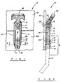
- a flexible draw latch 10 comprising a keeper 11, a mounting bracket 12, and a flexible arm member 13.
- the flexible arm is comprised of a flexible, resilient material, such as, for example, an elastomer.
- suitable elastomers include natural rubber and thermoplastic elastomer (TPE).
- TPE thermoplastic elastomer
- the keeper 11 is adapted for being affixed to a closure member, such, for example, the closure panel 100, and preferably comprises a substantially cylindrical body member 14 having a bore 15 disposed therein for mounting and a retaining lip 16 at the end thereof.
- a flange 17 is provided at the cylindrical member at the end thereof opposite the lip 16.
- the keeper 11 is affixed to a member, such as, for example, a corresponding frame or panel 100 with a screw 20 or other suitable fastener disposed within the bore 15 of cylindrical body portion 14.
- the flange 17 facilitates the retention of the keeper 11 and the distribution of the force load across the panel 100 or frame 101.
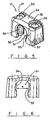
- the mounting bracket 12 is shown in a separate view in Fig. 5 .
- the mounting bracket 12 has mounting means for attachment of the mounting bracket 12 to a panel member, such as, for example, the closure panel 100 shown in Figs. 1-3 .
- the mounting means can comprise bores 26, 27 provided in the bracket 12 and through which fastening members, such as the screws 30, 31 as shown in Fig. 1 , extend to connect with the panel 100.
- fastening members can comprise threaded bolts which can extend through the panel 100 and be secured with a matingly associated nut.
- the mounting member 12 is provided with wells 32, 33 which are disposed in the upper surface 34 to accommodate the heads of the corresponding respective fastening members, such as the screws 30, 31.
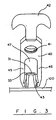
- the flexible arm member 13 is shown in Fig. 4 having a body portion 40 with a first aperture 41 therein, a lifting portion 42 disposed at one end thereof, and a mounting portion 43.
- the body portion 40 further has a pair of legs 45, 46 which connect with the mounting portion 43 to define a second aperture 47.
- the mounting bracket 12 is shown comprising a generally u-shaped configuration.
- the mounting bracket 50 further has a space 51 therein, through which, as shown in Fig. 4 , the mounting portion 43 of the flexible arm 13 passes.
- the mounting bracket 12 retains the flexible arm 13 of the latch 10 on the closure panel 100.
- the latch arm 13 is therefore able to pivot relative to the mounting bracket 12.
- the guide means is provided for facilitating the pivoting of the flexible arm member 13 throughout its pivot range.
- the guide means is shown in Fig. 4 comprising an annular groove 50 disposed in the mounting portion 43 of the arm 13.
- the annular groove 50 is tapered from each edge thereof to its center, forming a generally concave configuration.
- the guide means further is shown comprising groove-engaging means disposed on said mounting bracket 12 which is matingly associated for contact with the annular groove 50 of the flexible arm 13.
- the groove-engaging means preferably comprises an arcuate surface portion, such as the arcuate surfaces 55, 56 disposed on opposite sides of the mounting bracket space 51.
- posts or bosses 57, 58 can be employed on which the arcuate surfaces 55, 56 can be provided.
- the bosses 57, 58 preferably can have the mounting bores 26, 27 disposed therein.
- the radius of curvature of the arcuate surfaces 55, 56 is configured for mating association with the annular groove 50 of the arm mounting portion 43.
- the arcuate surfaces 55, 56 are spaced apart to narrow the opening 51 at a zone between the bosses 57, 58, the dimension of the narrowing defined by the distance between the bosses 57, 58 in this zone being represented by the double arrow "a" in Fig. 6 .
- the groove 50 of the mounting portion 43 is held between the bosses 57, 58 and is guided by the arcuate surfaces 55, 56 throughout its pivot range.
- the flexible arm 13 has a pivot range which permits the arm 13 to pivot from its fully open position shown by broken lines in Fig. 2 , to its latched position where it is secured to a keeper 11.
- bores 26, 27 can also be blind such that the bores end below the top surface 34 of the mounting bracket and are thus not visible.
- screws can be inserted into the bores 26, 27 such that the screw heads are positioned on the reverse side of the closure panel 100, relative to the side of the panel 100 on which the mounting bracket 12 is provided, in order to secure the mounting bracket 12 to the panel 100.
- the latch arm 13 is moved from its unlatched position by pivoting in the direction of double arrow "b" so that the first aperture 41 aligns with the keeper 11.
- the flexible arm member 13 preferably is stretched and the first aperture 41 drawn over the lip 16 of the keeper 11 and onto the keeper body 14.
- unlatching is accomplished by pulling the arm 13 to slightly stretch the arm 13 to allow the aperture 41 to clear the lip 16 of the keeper 11.
- the arm 13 may then be pivotally moved off of the keeper 11.
- the latch of the present invention due to the presence of a flexible, resilient locking member, provides all of the advantages associated with flexible draw latches.
- the flexibility of the locking member insures a positive latching action, even if the mounting bracket and the keeper are not in precise alignment, and thus compensates for misalignment of the bracket and keeper during installation.
- the load or tension generated by the locking member can be varied, within a particular range, by simply increasing or decreasing the distance between the mounting bracket and the keeper to provide a lesser or greater degree of stretch in the locking member when the latch is closed.
- the distance is too short the locking member will not properly engage the keeper and the latch will be ineffective.
- the latch will tend to release spontaneously because the stretch capabilities of the locking member have been exceeded.
- the minimum diameter of the mounting portion 43 at the bottom of the groove 50 and/or the dimensions of the groove 50 are selected such that there is frictional engagement between the arcuate surfaces 55 and 56 of the bosses 57 and 58 and the concave surface of the groove 50. This frictional engagement provides a hold-open feature by preventing uncontrolled pivotal movement of the arm 13 when the arm 13 is unlatched and not being actively moved by a user.
- the function of the groove 50 may optionally be enhanced by a pair of spaced-apart, annular projecting ridges provided on either side of the groove 50. These annular ridges would project radially outward relative to the remaining portions of the mounting portion 43. Also, these annular projecting ridges may in whole or in part define the annular groove 50.
- the lifting portion 42 is in the form of a T-shaped handle which is integrally made with the remaining portions of the arm 13.
- the lifting portion 42 provides a means for allowing a user to grasp and manipulate the arm 13. For example, the user may grasp the lifting portion 42 to stretch and pivotally move the arm 13.
- the keeper illustrated in Fig. 7 has a blind bore for engagement by a screw inserted from the side of the panel 101 opposite the side on which the keeper 11 is mounted.
- the keeper 11 may be provided with a counter-sunk through hole similar to bores 26 and 27, and the keeper may be secured to closure member 101 by a screw inserted through the top of the keeper such that the head of the screw is positioned near the end of the keeper having the lip 16.
- the invention disclosed herein is industrially applicable for releasably securing one closure member to another.
Landscapes
- Engineering & Computer Science (AREA)
- Mechanical Engineering (AREA)
- Clamps And Clips (AREA)
Claims (14)
- Flexibles Zugschloss (10) für die Verwendung bei der Verbindung zweier zu verschließender Elemente, welches umfasst:(a) ein Halteteil (11), das für die Befestigung an einem ersten zu verschließenden Element (101) ausgelegt ist,(b) einen Befestigungsbügel (12), der für die Befestigung an einem zweiten zu verschließenden Element (100) ausgelegt ist, und(c) einen flexiblen Arm (13), der schwenkbar mit dem Befestigungsbügel (12) verbunden und dafür ausgelegt ist, nach Wahl lösbar mit dem Halteteil (11) in Eingriff zu treten, wobei der Arm (13) einen Befestigungsabschnitt (43) an seinem einen Ende aufweist, der in schwenkbarer Verbindung mit dem Befestigungsbügel (12) gehalten wird,
gekennzeichnet dadurch, dass er ferner umfasst(d) ein Führungselement (50, 55, 56), das das Schwenken des flexiblen Arms (13) erleichtert, wobei das Führungselement eine Ringnut (50) umfasst, die auf dem Befestigungsabschnitt (43) des Arms (13) angeordnet ist, und ein Paar bogenförmiger Flächen (55, 56), die auf dem Befestigungsbügel (12) angeordnet sind. - Flexibles Zugschloss (10) nach Anspruch 1, wobei der flexible Arm (13) einen Hauptabschnitt umfasst, der eine erste Öffnung darin hat, einen Hebeabschnitt und einen Befestigungsabschnitt (43), wobei das Führungselement eine Ringnut (50) umfasst, die auf dem Befestigungsabschnitt (43) angebracht ist und wobei der Befestigungsbügel (12) mindestens einen Abschnitt umfasst, der sich in die Ringnut (50) erstreckt, um die Positionierung des Befestigungsabschnitts des flexiblen Arms im Verhältnis zu dem Befestigungsbügel zu erleichtern.
- Flexibles Zugschloss (10) nach Anspruch 2, wobei der mindestens eine Abschnitt des Befestigungsbügels (12), der sich in die Ringnut (50) erstreckt, reibschlüssig mit der Ringnut (50) in Eingriff tritt, um eine Offenhaltungsfunktion bereitzustellen, die unkontrolliert schwenkende Bewegungen des flexiblen Arms (13) verhindert, wenn der flexible Arm (13) entriegelt ist.
- Flexibles Zugschloss (10) nach Anspruch 1, wobei die Ringnut (50) eine konkave Ausgestaltung aufweist.
- Flexibles Zugschloss (10) nach Anspruch 4, wobei der Befestigungsbügel (12) passend ausgestaltete bogenförmige Abschnitte aufweist, die an jeder Seite der Ringnut (50) des Befestigungsabschnittes (43) angebracht sind, und wobei die bogenförmigen Abschnitte der konkaven Form der Ringnut (50) entsprechen.
- Flexibles Zugschloss (10) nach Anspruch 1, wobei die Ringnut (50) eine bogenförmige Ausgestaltung aufweist, und wobei der Befestigungsbügel (12) passend ausgestaltete bogenförmige Abschnitte aufweist, die zur Verwendung auf gegenüberliegenden Seiten des Befestigungsabschnittes (43) des flexiblen Arms (13) angebracht sind, wobei die Ringnut (50) derart angeordnet ist, dass sie mit den passend ausgestalteten bogenförmigen Abschnitten des Befestigungsbügels (12) in Eingriff tritt.
- Flexibles Zugschloss (10) nach Anspruch 1, wobei der flexible Arm (13) einen Hauptabschnitt mit einer ersten Öffnung darin, einen Hebeabschnitt umfasst, und wobei der flexible Arm ferner eine zweite Öffnung umfasst, die in dem Hauptabschnitt ausgebildet und teilweise durch den Befestigungsabschnitt (43) definiert ist, wobei der Befestigungsbügel (12) ein im Wesentlichen U-förmiges Element umfasst, das derart ausgelegt ist, dass es an das das zweite zu verschließendes Element montiert werden kann, und wobei der Befestigungsabschnitt (43) des flexiblen Arms (13) sich durch das im Wesentlichen U-förmige Element erstreckt und schwenkbar durch dieses gehalten wird, wenn der Befestigungsbügel (12) auf dem zweiten zu verschließendes Element montiert ist.
- Flexibles Zugschloss (10) nach Anspruch 1, wobei der flexible Arm (13) aus elastomerem Material besteht.
- Flexibles Zugschloss (10) nach Anspruch 8, wobei das elastomere Material ein thermoplastisches Elastomer ist.
- Flexibles Zugschloss (10) nach Anspruch 1, wobei der Befestigungsbügel (12) bogenförmige Flächen umfasst, die sich in die Ringnut (50) erstrecken, um das Führen des flexiblen Arms (13) in einem Schwenkbereich relativ zu dem Befestigungsbügel (12) zu erleichtern.
- Flexibles Zugschloss (10) nach Anspruch 2, wobei der flexible Arm (13) in einen länglichen Zustand gestreckt ist und eingezogen werden kann, wenn der flexible Arm (13) in einer vollständig geschlossenen Stellung ist.
- Flexibles Zugschloss (10) nach Anspruch 1,
wobei der flexible Arm (13) einen Hebebereich an seinem einen Ende und einen Befestigungsbereich (43) an seinem einen Ende aufweiset, und wobei der Befestigungsbügel (12) eine Öffnung durch diese aufweist, durch die sich der Befestigungsbereich (43) erstreckt, wobei sich die Ringnut (50) verjüngt, und eine im Wesentlichen konkave Ausgestaltung bildet, und
wobei der Befestigungsbügel (12) ein Paar Stützen aufweist, die an die Öffnung angrenzen und an gegenüberliegenden Seiten davon sowie an gegenüberliegende Seiten des Befestigungsbereiches (43) des flexiblen Arms (13) angeordnet sind, so dass die Stützen voneinander beabstandet angeordnet sind und einen Pfad dazwischen definieren, der die Öffnung durch den Befestigungsbügel (12) verengt. - Flexibles Zugschloss (10) nach Anspruch 12, wobei der flexible Arm (13) aus elastomerem Material besteht.
- Flexibles Zugschloss (10) nach Anspruch 13, wobei das elastomere Material ein thermoplastisches Elastomer ist.
Applications Claiming Priority (3)
| Application Number | Priority Date | Filing Date | Title |
|---|---|---|---|
| US557589 | 2000-04-22 | ||
| US09/557,589 US6398272B1 (en) | 2000-04-22 | 2000-04-22 | Flexible draw latch |
| PCT/US2001/012698 WO2001081697A1 (en) | 2000-04-22 | 2001-04-19 | Flexible draw latch |
Publications (3)
| Publication Number | Publication Date |
|---|---|
| EP1276948A1 EP1276948A1 (de) | 2003-01-22 |
| EP1276948A4 EP1276948A4 (de) | 2010-04-07 |
| EP1276948B1 true EP1276948B1 (de) | 2011-10-12 |
Family
ID=24226065
Family Applications (1)
| Application Number | Title | Priority Date | Filing Date |
|---|---|---|---|
| EP01927198A Expired - Lifetime EP1276948B1 (de) | 2000-04-22 | 2001-04-19 | Flexibler zugriegel |
Country Status (3)
| Country | Link |
|---|---|
| US (1) | US6398272B1 (de) |
| EP (1) | EP1276948B1 (de) |
| WO (1) | WO2001081697A1 (de) |
Cited By (2)
| Publication number | Priority date | Publication date | Assignee | Title |
|---|---|---|---|---|
| USD849253S1 (en) | 2015-04-17 | 2019-05-21 | Vision Quest Industries Incorporated | Orthotic device |
| US12186222B2 (en) | 2019-12-05 | 2025-01-07 | Vision Quest Industries Incorporated | Orthopedic device having wrap and single strap |
Families Citing this family (61)
| Publication number | Priority date | Publication date | Assignee | Title |
|---|---|---|---|---|
| US20110119859A1 (en) * | 2009-09-03 | 2011-05-26 | Frei Tibor | Latch arrangement |
| US8910819B2 (en) | 2010-11-29 | 2014-12-16 | Yeti Coolers, Llc | Insulating container and latching mechanism |
| US9328543B2 (en) * | 2012-11-29 | 2016-05-03 | B/E Aerospace, Inc. | Galley cart bay door latch |
| USD748452S1 (en) * | 2014-11-11 | 2016-02-02 | Rtic Coolers, LLC | Latch |
| USD747950S1 (en) * | 2014-11-11 | 2016-01-26 | Rtic Coolers, LLC | Latch |
| USD747951S1 (en) * | 2014-11-11 | 2016-01-26 | Rtic Coolers, LLC | Latch |
| USD750953S1 (en) * | 2014-11-11 | 2016-03-08 | Rtic Coolers, LLC | Latch |
| WO2016137729A1 (en) * | 2015-02-27 | 2016-09-01 | Sonoco Development, Inc. | Container with pivoting latch |
| US9994166B2 (en) * | 2015-08-19 | 2018-06-12 | Ford Global Technologies, Llc | Dual molded grab handle spacer for a motor vehicle |
| WO2017028478A1 (zh) * | 2015-08-19 | 2017-02-23 | 佛山市顺德区美的洗涤电器制造有限公司 | 用于洗碗机的洗涤篮组件、托盘组件及洗碗机 |
| US10807659B2 (en) | 2016-05-27 | 2020-10-20 | Joseph L. Pikulski | Motorized platforms |
| US10071303B2 (en) | 2015-08-26 | 2018-09-11 | Malibu Innovations, LLC | Mobilized cooler device with fork hanger assembly |
| USD818323S1 (en) | 2016-01-29 | 2018-05-22 | The Metal Ware Corporation | Plug for a cooler |
| USD807123S1 (en) * | 2016-01-29 | 2018-01-09 | The Metal Ware Corporation | Cooler |
| USD807124S1 (en) | 2016-01-29 | 2018-01-09 | The Metal Ware Corporation | Cooler |
| US11027907B2 (en) * | 2016-06-29 | 2021-06-08 | Eufouric Brands, Llc | Container with closures |
| USD933449S1 (en) | 2016-11-22 | 2021-10-19 | Dometic Sweden Ab | Latch |
| US11535425B2 (en) | 2016-11-22 | 2022-12-27 | Dometic Sweden Ab | Cooler |
| US10130171B2 (en) * | 2017-02-08 | 2018-11-20 | Intermetro Industries Corporation | Insulated transport cabinets for food and the like |
| USD844277S1 (en) | 2017-02-08 | 2019-03-26 | Intermetro Industries Corporation | Front-loaded insulated transport cabinet |
| USD873020S1 (en) | 2017-06-12 | 2020-01-21 | Yeti Coolers, Llc | Container |
| USD828028S1 (en) | 2017-06-12 | 2018-09-11 | Yeti Coolers, Llc | Container |
| USD828029S1 (en) | 2017-06-12 | 2018-09-11 | Yeti Coolers, Llc | Container |
| US12108853B2 (en) | 2019-01-06 | 2024-10-08 | Yeti Coolers, Llc | Luggage system |
| USD838983S1 (en) | 2017-06-12 | 2019-01-29 | Yeti Coolers, Llc | Container |
| US11976498B2 (en) | 2017-06-12 | 2024-05-07 | Yeti Coolers, Llc | Container and latching system |
| WO2018231826A1 (en) | 2017-06-12 | 2018-12-20 | Yeti Coolers, Llc | Container and latching system |
| USD872485S1 (en) | 2017-06-12 | 2020-01-14 | Yeti Coolers, Llc | Container |
| USD872478S1 (en) | 2017-06-12 | 2020-01-14 | Yeti Coolers, Llc | Container |
| USD869160S1 (en) | 2017-06-12 | 2019-12-10 | Yeti Coolers, Llc | Container |
| US11685573B2 (en) | 2017-06-12 | 2023-06-27 | Yeti Coolers, Llc | Carry strap for container |
| AU201717615S (en) | 2017-06-12 | 2018-01-15 | Yeti Coolers | Container |
| USD840150S1 (en) | 2017-06-12 | 2019-02-12 | Yeti Coolers, Llc | Container |
| USD838984S1 (en) | 2017-06-12 | 2019-01-29 | Yeti Coolers, Llc | Container |
| USD826027S1 (en) | 2017-06-19 | 2018-08-21 | The Metal Ware Corporation | Latch |
| USD836995S1 (en) | 2017-06-19 | 2019-01-01 | The Metal Ware Corporation | Cooler |
| USD845080S1 (en) * | 2017-10-23 | 2019-04-09 | Rtic Ip, Llc | Cooler |
| USD845082S1 (en) * | 2017-11-01 | 2019-04-09 | Rtic Ip, Llc | Cooler |
| USD845081S1 (en) * | 2017-11-01 | 2019-04-09 | Rtic Ip, Llc | Cooler |
| US10538365B2 (en) * | 2018-01-16 | 2020-01-21 | Cascade Mountain Technologies, Llc | Insulating device and latch |
| USD904829S1 (en) | 2018-12-11 | 2020-12-15 | Yeti Coolers, Llc | Container accessories |
| USD907445S1 (en) | 2018-12-11 | 2021-01-12 | Yeti Coolers, Llc | Container accessories |
| US10766672B2 (en) | 2018-12-12 | 2020-09-08 | Yeti Coolers, Llc | Insulating container |
| US11970313B2 (en) | 2018-12-12 | 2024-04-30 | Yeti Coolers, Llc | Insulating container |
| USD965409S1 (en) | 2018-12-12 | 2022-10-04 | Yeti Coolers, Llc | Latch portion |
| US12225993B2 (en) | 2019-01-06 | 2025-02-18 | Yeti Coolers, Llc | Luggage system |
| MX2021008199A (es) | 2019-01-06 | 2021-11-12 | Yeti Coolers Llc | Sistema de equipaje. |
| DE102019102491A1 (de) * | 2019-01-31 | 2020-08-06 | Hettich-Oni Gmbh & Co. Kg | Klappenbeschlag für ein Möbel |
| US11555644B2 (en) * | 2019-05-20 | 2023-01-17 | Wool Street LLC | Insulated cooler system |
| USD961926S1 (en) | 2020-06-30 | 2022-08-30 | Yeti Coolers, Llc | Luggage |
| USD963344S1 (en) | 2020-06-30 | 2022-09-13 | Yeti Coolers, Llc | Luggage |
| USD951643S1 (en) | 2020-06-30 | 2022-05-17 | Yeti Coolers, Llc | Luggage |
| USD954436S1 (en) | 2020-06-30 | 2022-06-14 | Yeti Coolers, Llc | Luggage |
| USD994438S1 (en) | 2020-12-16 | 2023-08-08 | Yeti Coolers, Llc | Container |
| USD985937S1 (en) | 2020-12-16 | 2023-05-16 | Yeti Coolers, Llc | Container |
| USD960648S1 (en) | 2020-12-16 | 2022-08-16 | Yeti Coolers, Llc | Container accessory |
| CN221852779U (zh) * | 2021-06-09 | 2024-10-18 | 科尔曼公司 | 冷却器 |
| US20230019028A1 (en) * | 2021-07-19 | 2023-01-19 | Evan Tull | Multi-Purpose Receptacle Lid Securement System |
| GB2626752B (en) * | 2023-01-31 | 2025-01-29 | Tailfin Ltd | A latch mechanism |
| USD1109584S1 (en) * | 2023-02-10 | 2026-01-20 | Southco, Inc. | Latch |
| USD1083550S1 (en) * | 2024-01-26 | 2025-07-15 | Solo Brands, Llc | Latch |
Family Cites Families (13)
| Publication number | Priority date | Publication date | Assignee | Title |
|---|---|---|---|---|
| US357240A (en) * | 1887-02-08 | Trunk-fastener | ||
| US1400953A (en) * | 1920-11-10 | 1921-12-20 | Carl R Hennicke | Hood-fastener |
| FR1139269A (fr) * | 1955-06-18 | 1957-06-27 | Système de verrouillage | |
| US3479701A (en) * | 1967-08-16 | 1969-11-25 | Gen Electric | Latch device |
| US3782765A (en) * | 1972-06-13 | 1974-01-01 | Caoutchouc Tech Soc | Latch assembly |
| US4270668A (en) * | 1980-02-05 | 1981-06-02 | Shop-Vac Corporation | Buckle or latch for holding lid to container |
| US4828298A (en) | 1986-11-07 | 1989-05-09 | Southco, Inc. | Flexible draw latch |
| US4804215A (en) | 1986-11-07 | 1989-02-14 | Southco, Inc. | Flexible draw latch |
| US4830413A (en) * | 1987-05-08 | 1989-05-16 | Southco, Inc. | Flexible draw latch |
| US4801165A (en) * | 1987-07-15 | 1989-01-31 | Buckhorn Rubber Products, Inc. | Hood latch |
| USD324165S (en) | 1989-10-04 | 1992-02-25 | Southco, Inc. | Flexible draw latch |
| USD333775S (en) | 1991-02-20 | 1993-03-09 | Southco, Inc. | Flexible draw latch |
| US6076865A (en) * | 1998-01-22 | 2000-06-20 | Southco, Inc. | Draw latch |
-
2000
- 2000-04-22 US US09/557,589 patent/US6398272B1/en not_active Expired - Lifetime
-
2001
- 2001-04-19 EP EP01927198A patent/EP1276948B1/de not_active Expired - Lifetime
- 2001-04-19 WO PCT/US2001/012698 patent/WO2001081697A1/en not_active Ceased
Cited By (3)
| Publication number | Priority date | Publication date | Assignee | Title |
|---|---|---|---|---|
| USD849253S1 (en) | 2015-04-17 | 2019-05-21 | Vision Quest Industries Incorporated | Orthotic device |
| USD898204S1 (en) | 2015-04-17 | 2020-10-06 | Vision Quest Industries Incorporated | Orthotic device |
| US12186222B2 (en) | 2019-12-05 | 2025-01-07 | Vision Quest Industries Incorporated | Orthopedic device having wrap and single strap |
Also Published As
| Publication number | Publication date |
|---|---|
| WO2001081697A1 (en) | 2001-11-01 |
| US6398272B1 (en) | 2002-06-04 |
| EP1276948A4 (de) | 2010-04-07 |
| EP1276948A1 (de) | 2003-01-22 |
Similar Documents
| Publication | Publication Date | Title |
|---|---|---|
| EP1276948B1 (de) | Flexibler zugriegel | |
| US4804215A (en) | Flexible draw latch | |
| US4830413A (en) | Flexible draw latch | |
| US4828298A (en) | Flexible draw latch | |
| US5728976A (en) | Detachable cover for wire ducts having a living hinge | |
| US4477947A (en) | Drawstring fastener | |
| US3889992A (en) | Latch assembly | |
| EP1095584B1 (de) | Zuglasche für Reissverschluss | |
| US5669638A (en) | Fastening device | |
| CA2317563A1 (en) | Swell latch assembly | |
| KR100361265B1 (ko) | 슬라이드 파스너용 슬라이더의 지퍼 견인부 | |
| EP0291816B1 (de) | Reissverschlussschieber | |
| US5078438A (en) | Gate closure latch | |
| US6305725B1 (en) | One-piece slam-action pawl latch | |
| US4644611A (en) | Snap hook | |
| US5586793A (en) | Lock for slide bolt latches | |
| US5492377A (en) | Window lock | |
| US12612812B2 (en) | Locks | |
| US20040148742A1 (en) | Cord locking device and an article including such device | |
| GB2293410A (en) | Snap buckle with a protective cover | |
| GB2352471A (en) | Attachment device | |
| EP0133051B1 (de) | Beschlagteil für ein Fenster, eine Tür oder ähnlichen Verschluss | |
| GB2197020A (en) | Fastening | |
| KR100322494B1 (ko) | 체인지 케이블 클립 | |
| KR930005031Y1 (ko) | 자물쇠 |
Legal Events
| Date | Code | Title | Description |
|---|---|---|---|
| PUAI | Public reference made under article 153(3) epc to a published international application that has entered the european phase |
Free format text: ORIGINAL CODE: 0009012 |
|
| 17P | Request for examination filed |
Effective date: 20021108 |
|
| AK | Designated contracting states |
Kind code of ref document: A1 Designated state(s): AT BE CH CY DE DK ES FI FR GB GR IE IT LI LU MC NL PT SE TR |
|
| RBV | Designated contracting states (corrected) |
Designated state(s): DE GB |
|
| A4 | Supplementary search report drawn up and despatched |
Effective date: 20100310 |
|
| RIC1 | Information provided on ipc code assigned before grant |
Ipc: E05B 15/02 20060101ALN20100304BHEP Ipc: E05C 19/06 20060101ALI20100304BHEP Ipc: E05C 19/10 20060101AFI20011105BHEP Ipc: E05B 65/19 20060101ALN20100304BHEP |
|
| 17Q | First examination report despatched |
Effective date: 20100802 |
|
| GRAP | Despatch of communication of intention to grant a patent |
Free format text: ORIGINAL CODE: EPIDOSNIGR1 |
|
| RIC1 | Information provided on ipc code assigned before grant |
Ipc: E05B 15/02 20060101ALN20110414BHEP Ipc: E05C 19/10 20060101AFI20110414BHEP Ipc: E05C 19/06 20060101ALI20110414BHEP Ipc: E05B 65/19 20060101ALN20110414BHEP |
|
| GRAS | Grant fee paid |
Free format text: ORIGINAL CODE: EPIDOSNIGR3 |
|
| GRAA | (expected) grant |
Free format text: ORIGINAL CODE: 0009210 |
|
| AK | Designated contracting states |
Kind code of ref document: B1 Designated state(s): DE GB |
|
| REG | Reference to a national code |
Ref country code: GB Ref legal event code: FG4D |
|
| REG | Reference to a national code |
Ref country code: DE Ref legal event code: R096 Ref document number: 60145500 Country of ref document: DE Effective date: 20111208 |
|
| PLBE | No opposition filed within time limit |
Free format text: ORIGINAL CODE: 0009261 |
|
| STAA | Information on the status of an ep patent application or granted ep patent |
Free format text: STATUS: NO OPPOSITION FILED WITHIN TIME LIMIT |
|
| 26N | No opposition filed |
Effective date: 20120713 |
|
| REG | Reference to a national code |
Ref country code: DE Ref legal event code: R097 Ref document number: 60145500 Country of ref document: DE Effective date: 20120713 |
|
| GBPC | Gb: european patent ceased through non-payment of renewal fee |
Effective date: 20120419 |
|
| PG25 | Lapsed in a contracting state [announced via postgrant information from national office to epo] |
Ref country code: GB Free format text: LAPSE BECAUSE OF NON-PAYMENT OF DUE FEES Effective date: 20120419 |
|
| PGFP | Annual fee paid to national office [announced via postgrant information from national office to epo] |
Ref country code: DE Payment date: 20140623 Year of fee payment: 14 |
|
| REG | Reference to a national code |
Ref country code: DE Ref legal event code: R119 Ref document number: 60145500 Country of ref document: DE |
|
| PG25 | Lapsed in a contracting state [announced via postgrant information from national office to epo] |
Ref country code: DE Free format text: LAPSE BECAUSE OF NON-PAYMENT OF DUE FEES Effective date: 20151103 |