EP1277164B1 - Fälschungsabwehr-authentifizierungsverfahren für optische speicherkarten und hybride chipkarten - Google Patents
Fälschungsabwehr-authentifizierungsverfahren für optische speicherkarten und hybride chipkarten Download PDFInfo
- Publication number
- EP1277164B1 EP1277164B1 EP01909110A EP01909110A EP1277164B1 EP 1277164 B1 EP1277164 B1 EP 1277164B1 EP 01909110 A EP01909110 A EP 01909110A EP 01909110 A EP01909110 A EP 01909110A EP 1277164 B1 EP1277164 B1 EP 1277164B1
- Authority
- EP
- European Patent Office
- Prior art keywords
- wavelength
- recording material
- optical
- reflectivity
- card
- Prior art date
- Legal status (The legal status is an assumption and is not a legal conclusion. Google has not performed a legal analysis and makes no representation as to the accuracy of the status listed.)
- Expired - Lifetime
Links
Images

Classifications
-
- G—PHYSICS
- G06—COMPUTING OR CALCULATING; COUNTING
- G06K—GRAPHICAL DATA READING; PRESENTATION OF DATA; RECORD CARRIERS; HANDLING RECORD CARRIERS
- G06K19/00—Record carriers for use with machines and with at least a part designed to carry digital markings
- G06K19/06—Record carriers for use with machines and with at least a part designed to carry digital markings characterised by the kind of the digital marking, e.g. shape, nature, code
- G06K19/08—Record carriers for use with machines and with at least a part designed to carry digital markings characterised by the kind of the digital marking, e.g. shape, nature, code using markings of different kinds or more than one marking of the same kind in the same record carrier, e.g. one marking being sensed by optical and the other by magnetic means
- G06K19/10—Record carriers for use with machines and with at least a part designed to carry digital markings characterised by the kind of the digital marking, e.g. shape, nature, code using markings of different kinds or more than one marking of the same kind in the same record carrier, e.g. one marking being sensed by optical and the other by magnetic means at least one kind of marking being used for authentication, e.g. of credit or identity cards
-
- G—PHYSICS
- G06—COMPUTING OR CALCULATING; COUNTING
- G06K—GRAPHICAL DATA READING; PRESENTATION OF DATA; RECORD CARRIERS; HANDLING RECORD CARRIERS
- G06K7/00—Methods or arrangements for sensing record carriers, e.g. for reading patterns
- G06K7/10—Methods or arrangements for sensing record carriers, e.g. for reading patterns by electromagnetic radiation, e.g. optical sensing; by corpuscular radiation
- G06K7/12—Methods or arrangements for sensing record carriers, e.g. for reading patterns by electromagnetic radiation, e.g. optical sensing; by corpuscular radiation using a selected wavelength, e.g. to sense red marks and ignore blue marks
-
- G—PHYSICS
- G07—CHECKING-DEVICES
- G07D—HANDLING OF COINS OR VALUABLE PAPERS, e.g. TESTING, SORTING BY DENOMINATIONS, COUNTING, DISPENSING, CHANGING OR DEPOSITING
- G07D7/00—Testing specially adapted to determine the identity or genuineness of valuable papers or for segregating those which are unacceptable, e.g. banknotes that are alien to a currency
- G07D7/06—Testing specially adapted to determine the identity or genuineness of valuable papers or for segregating those which are unacceptable, e.g. banknotes that are alien to a currency using wave or particle radiation
- G07D7/12—Visible light, infrared or ultraviolet radiation
- G07D7/1205—Testing spectral properties
-
- G—PHYSICS
- G07—CHECKING-DEVICES
- G07F—COIN-FREED OR LIKE APPARATUS
- G07F7/00—Mechanisms actuated by objects other than coins to free or to actuate vending, hiring, coin or paper currency dispensing or refunding apparatus
- G07F7/08—Mechanisms actuated by objects other than coins to free or to actuate vending, hiring, coin or paper currency dispensing or refunding apparatus by coded identity card or credit card or other personal identification means
- G07F7/086—Mechanisms actuated by objects other than coins to free or to actuate vending, hiring, coin or paper currency dispensing or refunding apparatus by coded identity card or credit card or other personal identification means by passive credit-cards adapted therefor, e.g. constructive particularities to avoid counterfeiting, e.g. by inclusion of a physical or chemical security-layer
Definitions
- the present invention relates to optical memory card security methods and apparatus.
- Optical memory cards are known. Such cards may be distinguished from electronic or flash memory cards which rely upon non-volatile integrated circuit chips to retain data. Optical memory cards contain laser recording material to contain data, similar to recordable compact disks called CD-Rs and may, or may not, also contain an integrated circuit chip. When an optical memory card also contains an integrated circuit chip it is known as a hybrid smart card. Providing security for optical data cards is an important consideration.
- U.S. Patent No. 5,932,865 to Drexler teaches a method for inhibiting the counterfeiting of electronic cash cards by bonding an optical memory stripe to the card, recording optical validation data on a specific location on the optical memory stripe by forming a plurality of spots in a surrounding field of reflective layer, reading the optical data on the stripe by detecting an optical reflective contrast between the surrounding field and the recorded spots and comparing the data to a reference.
- U.S. Patent No. 4,863,819 to Drexler teaches an optical data card comprising a film substrate layer, a highly reflective layer and an optical storage layer with a pattern of clear and partially clear data marks revealing reflectivity in the underlying reflective layer.
- the reflective layer is highly reflective at a read beam wavelength in the red or near infrared range and less reflective at actinic wavelengths either in the blue/green range or in the ultraviolet range.
- U.S. Patent No. 4,312,938 to Drexler teaches a method for making a broadband laser recording and storage data medium by a stepwise procedure involving normal photographic development of an exposed photosensitive silver-halide emulsion followed by fogging and silver diffusion transfer.
- U.S. Patent No. 4,745,268 to Drexler teaches the use of two optical systems to read visually readable information and laser recorded machine readable information on an information card.
- U.S. Patent No. 4,754,128 to Takeda et al teaches an optical card comprising a card substrate and a light reflective layer on the card substrate.
- the light reflective layer comprises an optical higher reflection layer and an optical lower reflection layer.
- the optical higher reflection layer has an optical information pattern formed.
- U.S. Patent No. 5,300,764 to Hoshino et al teaches an optical identification label consisting of an area of a hologram or diffraction grating which is transparent to visible light but reflects incident light with a specific reflective directivity. By identifying the reflectivity directivity, it is possible to identify the authenticity of the label and the object to which the identification label is affixed.
- optical memory cards are governmental agencies. Such cards are used by the Immigration and Naturalization Service (INS) for its Permanent Resident Card, also known as the "Green Card", and by the U.S. Department of State for its LaserVisa card used by Mexican citizens who make frequent visits to the USA. All of these cards use the Drexon TM media for laser recording of data, a registered trademark of Drexler Technology Corporation for a silver particle-based material. There is a concern about attempts to counterfeit these optical memory cards using reflective laser recording media other than Drexon TM media. Imitation laser recordable materials typically would use either vacuum deposited metal films or laser beam sensitive dyes.
- US 5,760,384 against which the claims are delimited, discloses a method of authentication of an optical storage medium where a broadband ray emitter emits light having different wavelengths onto the surface of the optical storage medium. Using two photo detectors the reflectivity of a recording material at different wavelengths is determined. The broad wavelengths band ray emitter emits in a range from 400-1000 nm. On the surface of the medium the reflectance of a first wave length is much higher than a second wave length. A discrimination of the optical storage medium being an authentic one or a faked medium is made by comparing the reflectance at the two different wavelengths.
- the predetermined (authentic) recording material is an infrared absorber.
- the authenticating system of US 5,568,251 uses a thin film multilayer coating on a substrate for optical verification. Due to the Etalon effect of the multilayer coating, the light emitted to the multilayer coating is differently reflected and absorbed in dependency of the wavelength. Sequentially light at different wavelengths is emitted to the coating and the reflected light is detected. The presence or absence of reflected light intensity at predetermined wavelengths within predetermined limits is used to determine the authenticity.
- Drexon TM a laser recording material
- Drexon TM a laser recording material
- An optical memory card containing an optical memory stripe or a hybrid smart card containing an optical memory stripe and an integrated circuit chip are proven to be authentic or nonauthentic by testing the optical properties of the optical memory stripe on the card. If the optical memory stripe of the card being tested exhibits the same optical reflectivity characteristics that silver particle-based laser recording material Drexon TM does at different wavelengths, the card is authentic. Otherwise, it is rejected.
- the reflective substrate being tested is illuminated with a beam of light generally in the red wavelength range.
- the optical reflectivity of the substrate is measured and recorded.
- the substrate is then illuminated with light of a different wavelength. If the optical reflectivity characteristics at both wavelengths displayed by the substrate being tested match the optical reflectivity characteristics of the silver particle-based laser recording material Drexon TM at the same wavelengths, the substrate is authentic and the card is accepted. This way, if a counterfeiter uses a material other than silver particle-based laser recording material Drexon TM in the optical recording strip, the unique reflectivity characteristics of Drexon TM will not be exhibited and the card will be rejected.
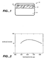
- an optical memory card 11 having a size common to most credit cards.
- the card's substrate material 13 is a dielectic, usually a plastic. Polycarbonate is preferred.
- the card carries a chip inside as shown in U.S. Patent Nos. 5,365,655 and 5,134,773 .
- the surface of the finish of the base for the card should have low specular reflectivity, preferably less than 10%.
- Substrate 13 carries strip or patch 17.
- the strip is typically 35mm or 16mm wide and extends the length of the card. Alternatively, the strip or patch may have other sizes and orientation.
- the strip is relatively thin, typically 60-200 microns, although this is not critical. Strips or patches of laser recording material may be applied to both sides of card 11. The strip or patch may be applied to the card by any convenient method which achieves flatness.
- the strip or patch 17 is adhered to the card with an adhesive and is covered by a transparent laminating sheet 76 seen in Fig. 4 which serves to keep strip 17 flat, as well as protecting the strip from dust and scratches.
- Sheet 76 is a thin, transparent plastic sheet laminating material or a coating such as a transparent lacquer. The material is preferably made of polycarbonate plastic.
- the high resolution laser recording material 74 which forms strip 17 is a reflective recording material which has been developed for use as a direct-read-after-write (DRAW) material.
- DRAW direct-read-after-write
- Materials which are preferred are those having a reflectivity of 25 to 55% and low power recording capability.
- Typical recording media are described in U.S. Patent Nos. 4,314,260 ; 4,298,684 ; 4,278,758 ; 4,278,756 and 4,269,917 , all assigned to the assignee of the present invention.
- the laser recording material which is selected should be compatible with the laser which is used for writing on it. Some materials are more sensitive than others at certain wavelengths. Good sensitivity to near infrared light is preferred because near infrared is affected least by scratches and dirt on the transparent laminating sheet.
- the selected recording material should have a favorable signal-to-noise ratio and form high contrast data bits with the read/write system with which it is used.
- the material should not lose data when subjected to temperatures of about 180°F (82°C) for long periods.
- the material should also be capable of recording at speeds of at least several thousand bits/second. This generally precludes the use of materials that require long heating times or that rely on slow chemical reactions in the presence of heat, which may permit recording of only a few bits/second.
- a large number of highly reflective laser recording materials have been used for optical data disk applications.
- Drexon TM the preferred recording material, consists of a thin, organic film or colloidal matrix that contains a thin layer of silver particles. Drexon TM is produced by a chemical silver diffusion transfer of photographic emulsions, creating a reflective recording surface. A method of making Drexon TM and the Drexon TM material are described in U.S. Patent Nos. 4,312,938 and 4,284,716 .
- a unique characteristic of the silver particle-based laser recording material is that it displays different reflectivity values at different wavelengths. For example, at near infrared wavelengths Drexon TM has a lower reflectivity than in the red wavelength. In contrast, a sputtered electrically conducting metal coating would have a relatively constant reflectivity over the same range of wavelengths.
- Fig. 2 illustrates how the reflectance of silver particle-based laser recording material Drexon TM varies with wavelength.
- Visible light has a wavelength of approximately 380nm to 700nm.
- red light has a wavelength range of approximately 630nm to 670nm.
- Infrared light has a wavelength range of 780nm or longer.
- Wavelengths at 570nm or shorter or 700nm or longer show a noticeable drop in reflectance.
- a card to be tested for validity is provided.
- the card has an optical memory strip bonded to it.
- a red light beam is focused onto the strip.
- the source of the red light beam is a helium-neon gas laser, a laser diode or a light emitting diode (LED).
- the reflected light beam is collected in a photodetector and the optical reflectivity is measured.
- at least one light beam outside of the red light wavelength range is focused onto the strip using an LED or semiconductor laser.
- the light beam may be of any wavelength which when focused on a silver particle-based laser recording material Drexon TM strip results in a reflectance value that is less than the reflectance value exhibited when a red light beam is focused on the silver particle-based laser recording material Drexon TM strip.
- Fig. 2 indicates the wavelengths of light which when focused on the Drexon TM strip cause a decrease in the reflectance of the strip when compared to the red wavelength range.
- a light beam having a wavelength that is either at least 140nm longer than or shorter than the wavelength of the red light beam is focused onto the strip being tested.
- the reflected light beam is collected in a photodetector and the optical reflectivity is measured.
- step 31 the reflectivity in the red wavelength of the strip being tested is compared with the reflectivity in the wavelength that is 140nm longer or shorter than the red wavelength of the strip being tested.
- a decision 80 is then made as to whether the card is valid, i.e. has a strip containing silver particle-based laser recording material Drexon TM . If the optical reflectivity of the substrate being tested in the red wavelength is at least 5% greater than the optical reflectivity of the substrate being tested in the wavelength that is at least 140nm longer or shorter than the red wavelength range, the card is accepted as indicated in step 82. This occurs when the strip being tested contains silver particle-based laser recording material Drexon TM , as is indicated by the curve in Fig.
- the card is rejected as indicated in step 84.
- more than two light beams of varying wavelengths may be focused on one substrate. The reflectivity of the substrate at different wavelengths may be measured sequentially.
- wavelengths other than those at least 140nm longer than or shorter than the red wavelength range may be used. However, these other wavelengths may result in a change in reflectance of the silver particle-based laser recording material Drexon TM surface that is not as noticeable.
- the wavelength that is at least 140nm longer or shorter than the red wavelength is preferred as it displays a more noticeable drop in reflectance when compared to the reflectance in the red wavelength range than does a wavelength that is not at least 140nm longer or shorter.
- a wavelength that is not at least 140nm longer or shorter than the wavelength of red light may be used, but a more precise measurement of reflectivity will be required which may require more expensive equipment.
- the card that is accepted displays the same unique reflectivity qualities that silver particle-based laser recording material Drexon TM does at different wavelengths.
- the strip may contain prerecorded data.
- Data is recorded by forming microscopic data spots in the field of the reflective layer itself, thereby altering the reflectivity in the data spot.
- Data is read by detecting the optical reflective contrast between the surrounding reflective field of unrecorded areas and the recorded spots. Spot reflectivity of less than half the reflectivity of the surrounding field produces a contrast ratio of at least two to one, which is more than sufficient contrast for reading. Reflectivity of the strip field of about 40% to 50% is preferred with reflectivity of a spot in the reflective field being less than 10%, thus creating a contrast ratio of four or five to one.
- Data strip 17 is intended to provide a data record and has digital information indicia.
- Digital machine readable data is written in individual tracks extending in a longitudinal direction, as indicated by the spot patterns 19 and are usually read in reflection, rather than in transmission.
- the information density is great because each of the spots in the spot pattern is approximately 0.6 to 3 microns in diameter with a typical spacing of about 0.6 to 3 microns between spots.
- the spots are recorded by a laser in the usual way, for example, as shown in U.S. Patent No. 4,278,756 to Bouldin et al .
- a card substrate 70 carries an optional secondary substrate 72 which is a thin flexible material, only a few mils thick carrying a laser recording material 74.
- the secondary substrate 72 is adhered to the primary substrate 70 by means of an adhesive or sticky substance.
- the laser recording material may be any of the materials previously discussed. However, in accord with the present invention, a silver particle-based laser recording material having variable reflectivity as a function of wavelength such as Drexon TM is used.
- a transparent protective coating or cover 76 is applied over the laser recording material.
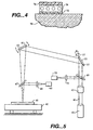
- a laser writing apparatus is illustrated in Fig. 5 which illustrates the side view of the lengthwise dimension of the medium of Fig. 1 consisting of a data strip having digital information in combination with microscopic data spot information on a card.
- the data strip portion 41 of the medium is usually received in a movable holder 42 which brings the strip into the trajectory of a laser beam.
- a laser light source 43 preferably a pulsed semiconductor laser of near infrared or red wavelength emits a beam 45 which passes through collimating and focusing optics 47.
- the beam is sampled by a beam splitter 49 which transmits a portion of the beam through a focusing lens 51 to a photodetector 53.
- the detector 53 confirms laser writing.
- the beam is then directed to a first servo controlled mirror 55 which is mounted for rotation along axis 57 in the direction indicated by arrows B.
- the purpose of the mirror 55 is to find lateral edges of the data strip in a coarse mode of operation and then in a fine mode of operation identify data paths or sites which exist predetermined distances from the edges.
- the beam is directed toward a mirror 61.
- the mirror is mounted for rotation at pivot 63.
- the purpose of the mirror 55 is for fine control of motion of the beam along the length of the data strip. Coarse control of the lengthwise portion of the data strip relative to the beam is achieved by motion of the movable holder 42.
- the position of the holder may be established by a linear motor and used by a closed loop position servo system of the type used in magnetic disk drives. Reference position information in the form of reflective data tracks is prerecorded or pre-formatted on the card so that position error signals may be generated and used as feedback in motor control.
- the mirror 55 Upon reading one data path, the mirror 55 is slightly rotated. The motor moves holder 42 lengthwise so that the path can be read again, and so on.
- mirror 55 For writing microscopic data spots, mirror 55 is used to identify sites at predetermined distances from the edges. Mirror 57 moves the scanning beam lengthwise from site to site. Upon reading one row of sites, mirror 55 is slightly rotated. Within a site, mirrors 55 and 57 cooperate to move the beam in either a zig-zag pattern or a raster-like pattern. Laser data spots are written at designated locations within a data track. When one site is written, mirrors 55 and 57 move the beam to the next site.
- the incident laser beam should deliver sufficient laser energy to the surface for the recording material to create microscopic data spots in the data writing mode, but should not cause significant disruption of the surface so as to cause difficulty in the lower beam power data and reading mode.
- the wavelength of the laser should be compatible with the recording material to achieve this purpose. In the read mode, power is approximately 5% to 10% of the recording or writing power.
- Differences in reflectivity between a data spot and surrounding material are detected by well-known methods.
- the reflectivity of the material surrounding a data spot, or the test spot is measured at different wavelengths as described above.
- the reflectivity of the test spot at the red wavelength is compared to the reflectivity of the test spot at one or more wavelengths that exhibit a decrease in reflectance when compared to the reflectance of silver particle-based laser recording material Drexon TM at the red wavelength range.
- a light beam with a wavelength at least 140nm longer than or shorter than the wavelength of the red light illuminates the surface being tested. Then, if the reflectivity in the red wavelength range of the substrate being tested is at least 5% greater than the reflectivity in the other range, the card is rendered authentic.
Landscapes
- Physics & Mathematics (AREA)
- Engineering & Computer Science (AREA)
- General Physics & Mathematics (AREA)
- Health & Medical Sciences (AREA)
- General Health & Medical Sciences (AREA)
- Toxicology (AREA)
- Theoretical Computer Science (AREA)
- Electromagnetism (AREA)
- Artificial Intelligence (AREA)
- Computer Vision & Pattern Recognition (AREA)
- Spectroscopy & Molecular Physics (AREA)
- Computer Security & Cryptography (AREA)
- Credit Cards Or The Like (AREA)
- Optical Recording Or Reproduction (AREA)
Claims (9)
- Verfahren zur Authentifizierung einer optischen Speicherkarte (11), die ein Aufzeichnungsmaterial (74) mit einem variablen, von der Wellenlänge abhängigen Reflexionsvermögen aufweist, wobei das Verfahren umfasst:Beleuchten einer Oberfläche des Aufzeichnungsmaterials (74) mit Licht mit einer ersten Wellenlänge im Bereich von 630 nm bis 670 nm und einer zweiten Wellenlänge;Reflektieren des Lichts von der getesteten Oberfläche, um das reflektierte Licht in einem Photodetektor (65) zu sammeln;Ermitteln der Werte des optischen Reflexionsvermögens des Lichts für die getestete Oberfläche bei den mindestens zwei Wellenlängen;Vergleichen der Werte des optischen Reflexionsvermögens der mindestens zwei Wellenlängen; undAkzeptieren der optischen Speicherkarte (11) als authentische Karte, die ein vorbestimmtes Aufzeichnungsmaterial (74) enthält, wenn der Wert des optischen Reflexionsvermögens der ersten Wellenlänge größer ist als der Wert des optischen Reflexionsvermögens der zweiten Wellenlänge;dadurch gekennzeichnet, dass
das vorbestimmte Aufzeichnungsmaterial (74) ein Laseraufzeichnungsmaterial auf Silberpartikelbasis ist;
der Beleuchtungsschritt das Beleuchten der Oberfläche des Laseraufzeichnungsmaterials (74) mit mindestens zwei einfallenden Lichtstrahlen (45) umfasst, wobei der erste einfallende Lichtstrahl die erste Wellenlänge aufweist und der zweite einfallende Lichtstrahl die zweite Wellenlänge aufweist; und
die zweite Wellenlänge kürzer als 550 nm oder länger als 730 nm ist. - Verfahren nach Anspruch 1, wobei die Basis der optischen Speicherkarte ein spiegelndes Reflexionsvermögen von weniger als 10 % aufweist.
- Verfahren nach Anspruch 1, wobei Testpunkte auf dem Laseraufzeichnungsmaterial (74), die verwendet werden, um die Reflexionsvermögenswerte zu messen, an verschiedenen Stellen liegen.
- Verfahren nach Anspruch 1, wobei die mindestens zwei einfallenden Lichtstrahlen durch eine Laserdiode oder eine Leuchtdiode erzeugt werden.
- Verfahren nach Anspruch 1, wobei der erste einfallende Lichtstrahl durch einen Helium-Neon-Gaslaser erzeugt wird.
- Verfahren nach Anspruch 1, wobei das Messen der Reflexionsvermögenswerte der mindestens zwei Wellenlängen nacheinander stattfindet.
- Verfahren nach Anspruch 1, wobei nur ein Photodetektor (65) verwendet wird, um die reflektierten Lichtstrahlen der ersten und der zweiten Wellenlänge zu erfassen.
- Verfahren nach Anspruch 1, wobei ein integrierter Schaltungschip an der optischen Speicherkarte (11) angebracht ist.
- Verfahren nach Anspruch 2, wobei die mindestens zwei einfallenden Lichtstrahlen um mindestens 140 Nanometer in der Wellenlänge voneinander getrennt sind.
Applications Claiming Priority (3)
| Application Number | Priority Date | Filing Date | Title |
|---|---|---|---|
| US09/548,703 US6290130B1 (en) | 2000-04-13 | 2000-04-13 | Anti-counterfeit authentication method for optical memory cards and hybrid smart cards |
| US548703 | 2000-04-13 | ||
| PCT/US2001/004390 WO2001080165A1 (en) | 2000-04-13 | 2001-02-08 | Anti-counterfeit authentication method for optical memory cards and hybrid smart cards |
Publications (3)
| Publication Number | Publication Date |
|---|---|
| EP1277164A1 EP1277164A1 (de) | 2003-01-22 |
| EP1277164A4 EP1277164A4 (de) | 2006-03-01 |
| EP1277164B1 true EP1277164B1 (de) | 2007-12-05 |
Family
ID=24190039
Family Applications (1)
| Application Number | Title | Priority Date | Filing Date |
|---|---|---|---|
| EP01909110A Expired - Lifetime EP1277164B1 (de) | 2000-04-13 | 2001-02-08 | Fälschungsabwehr-authentifizierungsverfahren für optische speicherkarten und hybride chipkarten |
Country Status (6)
| Country | Link |
|---|---|
| US (1) | US6290130B1 (de) |
| EP (1) | EP1277164B1 (de) |
| AU (1) | AU2001236896A1 (de) |
| CA (1) | CA2402782C (de) |
| DE (1) | DE60131740T2 (de) |
| WO (1) | WO2001080165A1 (de) |
Families Citing this family (8)
| Publication number | Priority date | Publication date | Assignee | Title |
|---|---|---|---|---|
| US6472238B1 (en) * | 2000-02-09 | 2002-10-29 | Therma-Wave, Inc. | Evaluation of etching processes in semiconductors |
| US7140540B2 (en) * | 2002-05-08 | 2006-11-28 | Lasercard Corporation | Method of making secure personal data card |
| US7143953B2 (en) * | 2002-12-27 | 2006-12-05 | Konica Minolta Holdings, Inc. | IC card, IC card manufacturing method, IC card manufacturing apparatus and IC card judgement system |
| US7128258B1 (en) | 2004-02-10 | 2006-10-31 | Bsi2000, Inc. | Optical immunization card |
| US7355944B2 (en) * | 2004-11-12 | 2008-04-08 | General Electric Company | Authenticatable media and method of authenticating |
| US20080106379A1 (en) * | 2006-11-03 | 2008-05-08 | Lasercard Corporation | Antenna using optical recording media |
| US8661889B2 (en) * | 2009-07-16 | 2014-03-04 | Duane C. Blake | AURA devices and methods for increasing rare coin value |
| FR3064790B1 (fr) * | 2017-03-30 | 2019-06-07 | Peripheriques Et Materiels De Controle P M C | Machine et procede de fonctionnement pour identifier un recepisse de pari frauduleux |
Family Cites Families (16)
| Publication number | Priority date | Publication date | Assignee | Title |
|---|---|---|---|---|
| US4312938A (en) | 1979-07-06 | 1982-01-26 | Drexler Technology Corporation | Method for making a broadband reflective laser recording and data storage medium with absorptive underlayer |
| US4745268A (en) | 1981-02-27 | 1988-05-17 | Drexler Technology Corporation | Personal information card system |
| CH653459A5 (de) * | 1981-04-16 | 1985-12-31 | Landis & Gyr Ag | Dokument mit einem sicherheitsfaden und verfahren zur echtheitspruefung desselben. |
| CH653162A5 (de) * | 1981-10-27 | 1985-12-13 | Landis & Gyr Ag | Einrichtung zur echtheitspruefung von dokumenten. |
| US4514085A (en) * | 1982-06-28 | 1985-04-30 | Beckman Instruments, Inc. | Marking and authenticating documents with liquid crystal materials |
| US4526466A (en) * | 1983-09-01 | 1985-07-02 | Rca Corporation | Technique for verifying genuineness of authenticating device |
| DE3650414T2 (de) | 1985-02-18 | 1996-06-20 | Dainippon Printing Co Ltd | Prozess zum Herstellen von optischen Datenkarten. |
| US4788129A (en) * | 1986-04-23 | 1988-11-29 | Drexler Technology Corporation | High contrast optical memory tape |
| US4863819A (en) | 1986-09-11 | 1989-09-05 | Drexler Technology Corporation | Read-only optical data card |
| US4983817A (en) * | 1989-03-01 | 1991-01-08 | Battelle Memorial Institute | Background compensating bar code readers |
| JP2561186B2 (ja) | 1991-09-11 | 1996-12-04 | 日本発条株式会社 | 対象物の識別構造 |
| DE4241663C2 (de) * | 1992-12-04 | 1997-05-28 | Borus Spezialverfahren | Verfahren zur Kennzeichnung und Erkennung eines Gegenstands |
| US5568251A (en) * | 1994-03-23 | 1996-10-22 | National Research Council Of Canada | Authenticating system |
| KR960032233A (ko) * | 1995-01-20 | 1996-09-17 | 후지타 히로미치 | 정보기억매체 |
| JP3068483B2 (ja) * | 1996-02-08 | 2000-07-24 | 株式会社東芝 | パターン読み出し方法、および光学的信号読み取り装置 |
| US5932865A (en) | 1996-12-09 | 1999-08-03 | Drexler Technology Corporation | Anti-counterfeit validation method for electronic cash cards employing an optical memory stripe |
-
2000
- 2000-04-13 US US09/548,703 patent/US6290130B1/en not_active Expired - Lifetime
-
2001
- 2001-02-08 WO PCT/US2001/004390 patent/WO2001080165A1/en not_active Ceased
- 2001-02-08 CA CA002402782A patent/CA2402782C/en not_active Expired - Fee Related
- 2001-02-08 EP EP01909110A patent/EP1277164B1/de not_active Expired - Lifetime
- 2001-02-08 DE DE60131740T patent/DE60131740T2/de not_active Expired - Fee Related
- 2001-02-08 AU AU2001236896A patent/AU2001236896A1/en not_active Abandoned
Also Published As
| Publication number | Publication date |
|---|---|
| EP1277164A4 (de) | 2006-03-01 |
| CA2402782A1 (en) | 2001-10-25 |
| CA2402782C (en) | 2008-10-07 |
| WO2001080165A1 (en) | 2001-10-25 |
| AU2001236896A1 (en) | 2001-10-30 |
| EP1277164A1 (de) | 2003-01-22 |
| DE60131740T2 (de) | 2008-10-30 |
| DE60131740D1 (de) | 2008-01-17 |
| US6290130B1 (en) | 2001-09-18 |
Similar Documents
| Publication | Publication Date | Title |
|---|---|---|
| CA2357002C (en) | Validation method for electronic cash cards and digital identity cards utilizing optical data storage | |
| EP0323969B1 (de) | Optisches datensystem mit doppelbündel | |
| US6318633B1 (en) | Method and system for laser writing on smart/optical cards data pixels usable in e-commerce transactions | |
| US5241165A (en) | Erasable optical wallet-size data card | |
| CA1262776A (en) | Personal information card system | |
| US5461239A (en) | Method and apparatus for coding and reading information in diffraction gratings using the divergence of diffracted light beams | |
| US4711996A (en) | Redundant optical recording of information in different formats | |
| US5421619A (en) | Laser imaged identification card | |
| US4680458A (en) | Laser recording and storage medium | |
| US4835376A (en) | Laser read/write system for personal information card | |
| GB2167595A (en) | A laser recordable wallet-size plastics card and a method of making same | |
| GB2167225A (en) | Data system containing a high capacity optical contrast laser recordable wallet-size plastics card | |
| EP0324831A1 (de) | Auslöschbare, optische datenkarte im taschenformat | |
| CA2402782C (en) | Anti-counterfeit authentication method for optical memory cards and hybrid smart cards | |
| US5932865A (en) | Anti-counterfeit validation method for electronic cash cards employing an optical memory stripe | |
| CA1215175A (en) | Optical data retrieval system using multi-spectral light sources | |
| US4362930A (en) | Data carrier card | |
| JPH01210391A (ja) | カード型メモリ | |
| KR940011671B1 (ko) | 정보 저장 카드용 진정성 확인 시스템 | |
| JPH10214321A (ja) | 記録カード、その使用方法及びその読みとり装置 | |
| JP2000048146A (ja) | 光記録媒体記録再生装置及び光記録媒体 | |
| JPH07120382B2 (ja) | 情報記憶カードの識別構造 | |
| JPH04238088A (ja) | 多値光記録媒体およびその読み出し方式 |
Legal Events
| Date | Code | Title | Description |
|---|---|---|---|
| PUAI | Public reference made under article 153(3) epc to a published international application that has entered the european phase |
Free format text: ORIGINAL CODE: 0009012 |
|
| 17P | Request for examination filed |
Effective date: 20021112 |
|
| AK | Designated contracting states |
Kind code of ref document: A1 Designated state(s): AT BE CH CY DE DK ES FI FR GB GR IE IT LI LU MC NL PT SE TR |
|
| AX | Request for extension of the european patent |
Free format text: AL;LT;LV;MK;RO;SI |
|
| RBV | Designated contracting states (corrected) |
Designated state(s): DE FR GB IT |
|
| RAP1 | Party data changed (applicant data changed or rights of an application transferred) |
Owner name: LASERCARD CORPORATION |
|
| A4 | Supplementary search report drawn up and despatched |
Effective date: 20060118 |
|
| RIC1 | Information provided on ipc code assigned before grant |
Ipc: G01N 21/17 20060101ALI20060112BHEP Ipc: G01J 3/00 20060101ALI20060112BHEP Ipc: G07D 7/06 20060101ALI20060112BHEP Ipc: G07F 7/08 20060101ALI20060112BHEP Ipc: G06K 7/08 20060101ALI20060112BHEP Ipc: G06K 19/06 20060101ALI20060112BHEP Ipc: G06K 7/10 20060101AFI20011101BHEP |
|
| 17Q | First examination report despatched |
Effective date: 20060518 |
|
| GRAP | Despatch of communication of intention to grant a patent |
Free format text: ORIGINAL CODE: EPIDOSNIGR1 |
|
| GRAS | Grant fee paid |
Free format text: ORIGINAL CODE: EPIDOSNIGR3 |
|
| GRAA | (expected) grant |
Free format text: ORIGINAL CODE: 0009210 |
|
| AK | Designated contracting states |
Kind code of ref document: B1 Designated state(s): DE FR GB IT |
|
| REG | Reference to a national code |
Ref country code: GB Ref legal event code: FG4D |
|
| REF | Corresponds to: |
Ref document number: 60131740 Country of ref document: DE Date of ref document: 20080117 Kind code of ref document: P |
|
| PGFP | Annual fee paid to national office [announced via postgrant information from national office to epo] |
Ref country code: IT Payment date: 20080225 Year of fee payment: 8 Ref country code: GB Payment date: 20080226 Year of fee payment: 8 Ref country code: DE Payment date: 20080229 Year of fee payment: 8 |
|
| ET | Fr: translation filed | ||
| PGFP | Annual fee paid to national office [announced via postgrant information from national office to epo] |
Ref country code: FR Payment date: 20080225 Year of fee payment: 8 |
|
| PLBE | No opposition filed within time limit |
Free format text: ORIGINAL CODE: 0009261 |
|
| STAA | Information on the status of an ep patent application or granted ep patent |
Free format text: STATUS: NO OPPOSITION FILED WITHIN TIME LIMIT |
|
| 26N | No opposition filed |
Effective date: 20080908 |
|
| GBPC | Gb: european patent ceased through non-payment of renewal fee |
Effective date: 20090208 |
|
| REG | Reference to a national code |
Ref country code: FR Ref legal event code: ST Effective date: 20091030 |
|
| PG25 | Lapsed in a contracting state [announced via postgrant information from national office to epo] |
Ref country code: DE Free format text: LAPSE BECAUSE OF NON-PAYMENT OF DUE FEES Effective date: 20090901 |
|
| PG25 | Lapsed in a contracting state [announced via postgrant information from national office to epo] |
Ref country code: GB Free format text: LAPSE BECAUSE OF NON-PAYMENT OF DUE FEES Effective date: 20090208 Ref country code: FR Free format text: LAPSE BECAUSE OF NON-PAYMENT OF DUE FEES Effective date: 20090302 |
|
| PG25 | Lapsed in a contracting state [announced via postgrant information from national office to epo] |
Ref country code: IT Free format text: LAPSE BECAUSE OF NON-PAYMENT OF DUE FEES Effective date: 20090208 |