EP1277261B1 - Dispositif calorifuge, notamment pour des corps allonges - Google Patents
Dispositif calorifuge, notamment pour des corps allonges Download PDFInfo
- Publication number
- EP1277261B1 EP1277261B1 EP01925575A EP01925575A EP1277261B1 EP 1277261 B1 EP1277261 B1 EP 1277261B1 EP 01925575 A EP01925575 A EP 01925575A EP 01925575 A EP01925575 A EP 01925575A EP 1277261 B1 EP1277261 B1 EP 1277261B1
- Authority
- EP
- European Patent Office
- Prior art keywords
- arrangement according
- protective arrangement
- thermally protective
- protective layer
- thermally
- Prior art date
- Legal status (The legal status is an assumption and is not a legal conclusion. Google has not performed a legal analysis and makes no representation as to the accuracy of the status listed.)
- Expired - Lifetime
Links
- 238000009413 insulation Methods 0.000 title abstract description 10
- 239000011241 protective layer Substances 0.000 claims abstract description 93
- 230000001681 protective effect Effects 0.000 claims description 63
- 229910052751 metal Inorganic materials 0.000 claims description 55
- 239000002184 metal Substances 0.000 claims description 55
- 239000010410 layer Substances 0.000 claims description 40
- 239000011521 glass Substances 0.000 claims description 37
- 239000003365 glass fiber Substances 0.000 claims description 28
- 238000005470 impregnation Methods 0.000 claims description 22
- 239000011248 coating agent Substances 0.000 claims description 12
- 239000004033 plastic Substances 0.000 claims description 10
- 229920003023 plastic Polymers 0.000 claims description 10
- 239000010935 stainless steel Substances 0.000 claims description 10
- 229910001220 stainless steel Inorganic materials 0.000 claims description 10
- 229910000570 Cupronickel Inorganic materials 0.000 claims description 8
- YOCUPQPZWBBYIX-UHFFFAOYSA-N copper nickel Chemical compound [Ni].[Cu] YOCUPQPZWBBYIX-UHFFFAOYSA-N 0.000 claims description 8
- 238000000576 coating method Methods 0.000 claims description 7
- 229910045601 alloy Inorganic materials 0.000 claims description 6
- 239000000956 alloy Substances 0.000 claims description 6
- 229910052782 aluminium Inorganic materials 0.000 claims description 6
- 229920002635 polyurethane Polymers 0.000 claims description 6
- 239000004814 polyurethane Substances 0.000 claims description 6
- 229920002379 silicone rubber Polymers 0.000 claims description 6
- 239000004945 silicone rubber Substances 0.000 claims description 6
- RYGMFSIKBFXOCR-UHFFFAOYSA-N Copper Chemical compound [Cu] RYGMFSIKBFXOCR-UHFFFAOYSA-N 0.000 claims description 5
- 229920002050 silicone resin Polymers 0.000 claims description 5
- 238000005507 spraying Methods 0.000 claims description 5
- XAGFODPZIPBFFR-UHFFFAOYSA-N aluminium Chemical compound [Al] XAGFODPZIPBFFR-UHFFFAOYSA-N 0.000 claims description 4
- VYPSYNLAJGMNEJ-UHFFFAOYSA-N Silicium dioxide Chemical compound O=[Si]=O VYPSYNLAJGMNEJ-UHFFFAOYSA-N 0.000 claims description 2
- 229910052802 copper Inorganic materials 0.000 claims description 2
- 239000010949 copper Substances 0.000 claims description 2
- 238000007654 immersion Methods 0.000 claims description 2
- 238000002791 soaking Methods 0.000 claims description 2
- 239000004753 textile Substances 0.000 claims description 2
- 239000012255 powdered metal Substances 0.000 claims 2
- 229920000271 Kevlar® Polymers 0.000 claims 1
- 239000004411 aluminium Substances 0.000 claims 1
- 229910010293 ceramic material Inorganic materials 0.000 claims 1
- 239000000470 constituent Substances 0.000 claims 1
- 239000003431 cross linking reagent Substances 0.000 claims 1
- 239000004761 kevlar Substances 0.000 claims 1
- 239000004005 microsphere Substances 0.000 claims 1
- 238000011084 recovery Methods 0.000 claims 1
- 230000000284 resting effect Effects 0.000 claims 1
- 230000002459 sustained effect Effects 0.000 claims 1
- 239000003981 vehicle Substances 0.000 claims 1
- 239000004020 conductor Substances 0.000 description 23
- 239000004744 fabric Substances 0.000 description 23
- 229920001296 polysiloxane Polymers 0.000 description 13
- 238000005299 abrasion Methods 0.000 description 11
- 230000017525 heat dissipation Effects 0.000 description 10
- 238000009940 knitting Methods 0.000 description 10
- 239000000463 material Substances 0.000 description 6
- 238000005520 cutting process Methods 0.000 description 5
- 230000015572 biosynthetic process Effects 0.000 description 4
- 239000000834 fixative Substances 0.000 description 4
- 230000007774 longterm Effects 0.000 description 3
- -1 polypropylene Polymers 0.000 description 3
- 150000003839 salts Chemical class 0.000 description 3
- 238000009991 scouring Methods 0.000 description 3
- 239000002966 varnish Substances 0.000 description 3
- 239000004971 Cross linker Substances 0.000 description 2
- 239000004952 Polyamide Substances 0.000 description 2
- 239000004743 Polypropylene Substances 0.000 description 2
- 239000004809 Teflon Substances 0.000 description 2
- 229920006362 Teflon® Polymers 0.000 description 2
- AZDRQVAHHNSJOQ-UHFFFAOYSA-N alumane Chemical compound [AlH3] AZDRQVAHHNSJOQ-UHFFFAOYSA-N 0.000 description 2
- 239000004760 aramid Substances 0.000 description 2
- 238000001816 cooling Methods 0.000 description 2
- 230000007797 corrosion Effects 0.000 description 2
- 238000005260 corrosion Methods 0.000 description 2
- 230000006378 damage Effects 0.000 description 2
- 230000000694 effects Effects 0.000 description 2
- 239000012530 fluid Substances 0.000 description 2
- 238000004519 manufacturing process Methods 0.000 description 2
- 230000000149 penetrating effect Effects 0.000 description 2
- 229920002647 polyamide Polymers 0.000 description 2
- 229920001155 polypropylene Polymers 0.000 description 2
- 239000000843 powder Substances 0.000 description 2
- 125000006850 spacer group Chemical group 0.000 description 2
- XLYOFNOQVPJJNP-UHFFFAOYSA-N water Substances O XLYOFNOQVPJJNP-UHFFFAOYSA-N 0.000 description 2
- VYZAMTAEIAYCRO-UHFFFAOYSA-N Chromium Chemical compound [Cr] VYZAMTAEIAYCRO-UHFFFAOYSA-N 0.000 description 1
- 229920000114 Corrugated plastic Polymers 0.000 description 1
- 229910000792 Monel Inorganic materials 0.000 description 1
- 208000027418 Wounds and injury Diseases 0.000 description 1
- 238000010521 absorption reaction Methods 0.000 description 1
- 229920006231 aramid fiber Polymers 0.000 description 1
- 229920003235 aromatic polyamide Polymers 0.000 description 1
- 238000005452 bending Methods 0.000 description 1
- 230000015556 catabolic process Effects 0.000 description 1
- 239000000919 ceramic Substances 0.000 description 1
- 238000002144 chemical decomposition reaction Methods 0.000 description 1
- 239000003795 chemical substances by application Substances 0.000 description 1
- 229910052804 chromium Inorganic materials 0.000 description 1
- 239000011651 chromium Substances 0.000 description 1
- 238000010073 coating (rubber) Methods 0.000 description 1
- 238000010276 construction Methods 0.000 description 1
- 230000001419 dependent effect Effects 0.000 description 1
- 230000005489 elastic deformation Effects 0.000 description 1
- 229920001971 elastomer Polymers 0.000 description 1
- 238000004870 electrical engineering Methods 0.000 description 1
- 238000010292 electrical insulation Methods 0.000 description 1
- 230000009970 fire resistant effect Effects 0.000 description 1
- 230000008642 heat stress Effects 0.000 description 1
- 238000010438 heat treatment Methods 0.000 description 1
- 239000003779 heat-resistant material Substances 0.000 description 1
- 208000014674 injury Diseases 0.000 description 1
- 239000011810 insulating material Substances 0.000 description 1
- 239000004922 lacquer Substances 0.000 description 1
- 238000002844 melting Methods 0.000 description 1
- 230000008018 melting Effects 0.000 description 1
- 238000000034 method Methods 0.000 description 1
- 239000003973 paint Substances 0.000 description 1
- 239000000049 pigment Substances 0.000 description 1
- 229920000573 polyethylene Polymers 0.000 description 1
- 229920000915 polyvinyl chloride Polymers 0.000 description 1
- 239000004800 polyvinyl chloride Substances 0.000 description 1
- 230000001012 protector Effects 0.000 description 1
- 230000000717 retained effect Effects 0.000 description 1
- 238000000926 separation method Methods 0.000 description 1
- 238000010008 shearing Methods 0.000 description 1
- 238000007711 solidification Methods 0.000 description 1
- 230000008023 solidification Effects 0.000 description 1
- 239000004834 spray adhesive Substances 0.000 description 1
- 230000006641 stabilisation Effects 0.000 description 1
- 238000011105 stabilization Methods 0.000 description 1
- 230000035882 stress Effects 0.000 description 1
- 239000000126 substance Substances 0.000 description 1
- 230000008093 supporting effect Effects 0.000 description 1
Images




Classifications
-
- B—PERFORMING OPERATIONS; TRANSPORTING
- B60—VEHICLES IN GENERAL
- B60R—VEHICLES, VEHICLE FITTINGS, OR VEHICLE PARTS, NOT OTHERWISE PROVIDED FOR
- B60R16/00—Electric or fluid circuits specially adapted for vehicles and not otherwise provided for; Arrangement of elements of electric or fluid circuits specially adapted for vehicles and not otherwise provided for
- B60R16/02—Electric or fluid circuits specially adapted for vehicles and not otherwise provided for; Arrangement of elements of electric or fluid circuits specially adapted for vehicles and not otherwise provided for electric constitutive elements
- B60R16/0207—Wire harnesses
- B60R16/0215—Protecting, fastening and routing means therefor
-
- H—ELECTRICITY
- H02—GENERATION; CONVERSION OR DISTRIBUTION OF ELECTRIC POWER
- H02G—INSTALLATION OF ELECTRIC CABLES OR LINES, OR OF COMBINED OPTICAL AND ELECTRIC CABLES OR LINES
- H02G15/00—Cable fittings
- H02G15/08—Cable junctions
-
- H—ELECTRICITY
- H02—GENERATION; CONVERSION OR DISTRIBUTION OF ELECTRIC POWER
- H02G—INSTALLATION OF ELECTRIC CABLES OR LINES, OR OF COMBINED OPTICAL AND ELECTRIC CABLES OR LINES
- H02G15/00—Cable fittings
- H02G15/08—Cable junctions
- H02G15/18—Cable junctions protected by sleeves, e.g. for communication cable
-
- D—TEXTILES; PAPER
- D07—ROPES; CABLES OTHER THAN ELECTRIC
- D07B—ROPES OR CABLES IN GENERAL
- D07B2201/00—Ropes or cables
- D07B2201/20—Rope or cable components
- D07B2201/2083—Jackets or coverings
- D07B2201/2088—Jackets or coverings having multiple layers
-
- D—TEXTILES; PAPER
- D07—ROPES; CABLES OTHER THAN ELECTRIC
- D07B—ROPES OR CABLES IN GENERAL
- D07B2201/00—Ropes or cables
- D07B2201/20—Rope or cable components
- D07B2201/2083—Jackets or coverings
- D07B2201/209—Jackets or coverings comprising braided structures
-
- D—TEXTILES; PAPER
- D07—ROPES; CABLES OTHER THAN ELECTRIC
- D07B—ROPES OR CABLES IN GENERAL
- D07B2201/00—Ropes or cables
- D07B2201/20—Rope or cable components
- D07B2201/2083—Jackets or coverings
- D07B2201/20907—Jackets or coverings comprising knitted structures
-
- D—TEXTILES; PAPER
- D07—ROPES; CABLES OTHER THAN ELECTRIC
- D07B—ROPES OR CABLES IN GENERAL
- D07B2205/00—Rope or cable materials
- D07B2205/30—Inorganic materials
- D07B2205/3021—Metals
- D07B2205/3085—Alloys, i.e. non ferrous
-
- D—TEXTILES; PAPER
- D07—ROPES; CABLES OTHER THAN ELECTRIC
- D07B—ROPES OR CABLES IN GENERAL
- D07B2401/00—Aspects related to the problem to be solved or advantage
- D07B2401/20—Aspects related to the problem to be solved or advantage related to ropes or cables
- D07B2401/202—Environmental resistance
- D07B2401/2035—High temperature resistance
-
- H—ELECTRICITY
- H02—GENERATION; CONVERSION OR DISTRIBUTION OF ELECTRIC POWER
- H02G—INSTALLATION OF ELECTRIC CABLES OR LINES, OR OF COMBINED OPTICAL AND ELECTRIC CABLES OR LINES
- H02G3/00—Installations of electric cables or lines or protective tubing therefor in or on buildings, equivalent structures or vehicles
- H02G3/02—Details
- H02G3/04—Protective tubing or conduits, e.g. cable ladders or cable troughs
- H02G3/0462—Tubings, i.e. having a closed section
- H02G3/0481—Tubings, i.e. having a closed section with a circular cross-section
Definitions
- the invention relates to a particularly abrasion and abrasion resistant Thermal protection device, in particular for sheathing elongated bodies near heat sources, e.g. in Motor vehicles.
- elongated are usually elongated in motor vehicle construction or elongated bodies, e.g. Fluid lines, such as hydraulic or Pneumatic lines or pneumatic hoses, or electrical Cable harnesses to protect against mechanical influences, in particular for protection against heat and abrasion and against abrasion e.g. covered with corrugated plastic pipes.
- Fluid lines such as hydraulic or Pneumatic lines or pneumatic hoses, or electrical Cable harnesses to protect against mechanical influences, in particular for protection against heat and abrasion and against abrasion e.g. covered with corrugated plastic pipes.
- corrugated tubes also grouping the conductor wires into a wiring harness reached.
- Common corrugated pipes are made of polypropylene or polyamide and have only a limited thermal resilience so that electrical lines, hoses or the like, which, for example, in vehicles near heat sources, e.g. near the engine, a turbocharger, an exhaust system or the like are laid through such corrugated pipes are not adequately protected from damaging heat.
- Glass fiber hoses are known, for example on the outside are overmolded with a silicone layer.
- a silicone layer is to protect against electrical Breakdown, i.e. to optimize electrical insulation properties known.
- a protective device coated in this way is also in a temperature range up to approx. 250 ° C briefly mechanically resistant. In temperature ranges The silicone layer is damaged above 250 ° C, so that its mechanical and thermal protective effect is lost.
- Such a heat protection device is from the publications GB-A-2 184 512, DE-A-198 00 167 and WO-A-9904 194 are known.
- the object of the invention is to provide a heat protection device for Bodies, especially elongated bodies such as Wiring harnesses or To create fluid lines, which are particularly high zonal heat load withstands long term and prevents the heat can damage the protected body.
- the heat protection device should also be insensitive against mechanical stress, such as chafing and Be abrasion.
- the heat protection device should also be flexible simply constructed and inexpensive to manufacture.
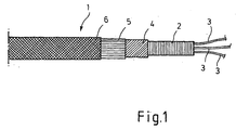
- Thermal protection device 1 hereinafter also protective device called, for sheathing, for example, in a corrugated tube 2 or electrical wire 3 laid as a wire harness a first inner one pointing to the conductor wires 3 to be encased heat-resistant protective layer 4, a second, the inner Protective layer 4 surrounding heat-dissipating protective layer 5 and preferably an outer, surrounding the heat dissipation layer 5 third protective layer 6, which is also heat-dissipating and mechanically resistant protective layer is formed on.
- the first inner heat-resistant protective layer 4 is preferably designed as a braided or bobbin-made tube body, the braided strands being made of glass filament threads.
- the first inner protective layer 4 is preferably designed as a braided glass silk tube, the filaments being made of an E glass, a D glass, an R glass or an AR glass, preferably of an E glass with a density ⁇ ⁇ 2.6 g / cm 3 are produced.
- the glass filaments have their softening point in the range between about 770 ° C and 990 ° C, especially at about 845 ° C (E-glass). Such glass filaments have a heat resistance with essentially unchanged properties up to approx. 400 ° C (for E glass) or 700 ° C (for R glass) and 1100 ° C (AR glass).
- the glass filaments have a relatively low thermal conductivity ⁇ , which is approximately 0.8 to 1.2 W / mK, in particular 1.0 W / mK.
- the Glass filaments have a tensile strength of approximately 2500 MPa, in particular up to 3400 MPa (E-glass).
- Glass fiber hoses from the Glass filaments mentioned are also fire resistant and not combustible.
- the first inner, heat-resistant protective layer 4 is also advantageously 'impregnated or lacquered with it a mechanical bond between the filaments or threads is formed and thus the glass fiber hose is a permanent, receives a self-supporting spatial shape in cross-section and maintains this during further processing or processing.
- Impregnations are suitable as impregnation for the glass silk tube based on silicone or polyurethane, the Silicone impregnation temperature resistant up to about 220 ° C and the polyurethane impregnation temperature resistant up to about 155 ° C is.
- the less expensive impregnations are advantageous selected from polyurethane and silicone.
- the impregnation or impregnation of the glass silk tube material with lacquer only serves to stabilize the shape of the glass fiber tube until assembly.
- the impregnation or varnish impregnation of the glass silk hose also facilitates the handling of the glass fiber hoses because at one end of the cut edge of the glass silk hoses Threads or filaments held together by the impregnation and thus fraying at the ends of the glass fiber tube is reliably prevented.
- the second protective layer 5 consists of a good heat conductor Material, in particular made of metal e.g. made of a copper-nickel alloy (e.g. NiCu30Fe) and is a metal wire mesh structure, especially as a textile mesh structure, e.g. as Wire mesh or knitted wire formed.
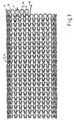
- the second protective layer 5 as a catchy metal wire knit from a metal wire 8 trained.
- the metal wire 8 is e.g. from one Copper-nickel alloy and has a diameter of e.g. 0.114 mm.
- the wire 8 is by means of a circular knitting process tangled in a spiral all the way around, so that stitches 9 are trained.
- the stitches 9 have a stitch height H, too Called mesh length, in the range of 0.5 to 4 mm, in particular 1.0 to 2.0 mm and have a mesh spacing W, also called mesh division, for example 1 to 4 mm, in particular 1.4 to 2.5 mm.
- Fig. 4 is the second Protective layer 5 by means of two wires 10, 11 in a two-thread spiral circular knitted, each formed by the wire 10 Stitches 10a forming free stitches 11a are connected by means of the wire 11, the free stitches 11a in the following circulation in the same way from the wire 10 are connected to form free stitches 10a.
- Such a thing two-course knitting of two wires 10, 11 has the advantage that after cutting off such a knitted tube body in In contrast to the catchy tubular body an unintentional one Separation from an end e.g. Cutting edge of the Hose body is prevented because e.g.
- the second protective layer 5 is optionally adjacent a third protective layer 6, which is considered to be mechanically resistant and preferably also formed a heat-dissipating protective layer is arranged.
- the outermost protective layer 6 is analog to the second protective layer 5 as a metal wire mesh structure, formed in particular as a metal wire mesh, the Knitting wire 8, 10, 11 (see FIG. 3) preferably from a stainless steel, in particular containing 12% to 18% chromium is trained. It is essential that for the material of the outermost Protective layer 6 a metal is selected, which in the electro-chemical voltage series close to that for the second Protective layer 5 is selected metal, so that under the influence of moisture an electro-chemical decomposition of the knitted metal is avoided.
- the mesh size W and the mesh height H of the protective layer 6 can be the same as that of the protective layer 5 but they are expediently a little larger or smaller, thus the protective layer 6 outside the protective layer 5 lies and the meshes of the layers 5, 6 not if possible can interlock. This ensures that the meshes Protective layer 5 does not come into contact with a part of the scouring partner come and are not destroyed.
- a protective device 1 according to the invention is basically suitable for direct sheathing of individual conductor wires 3, in particular a layer structure made of a glass fiber tube 4, a second protective layer 5 e.g. from a copper-nickel alloy knitted fabric and possibly an outermost one Protective layer 6 e.g. made from a stainless steel knit.
- the object to be protected e.g. the wire bundle Lay the conductor wires 3 in an area in which a very high, there is peak-like and temporary heat exposure, such as. in congested heat areas after parking a motor vehicle, so is between the protective device 1 and the protective object expediently arranged a corrugated tube 2, in which the conductor wires 3 to be protected are laid. Due to the geometry of the corrugated tube 2 only touch the wave crests, the innermost protective layer 4 and the wave troughs the conductor wires 3, so that the heat input from the protective layer 4 is reduced in the corrugated tube 2.
- the corrugated tube 2 as a spacer between the Conductor wires 3 and the first protective layer 4 acts, the in the groove-shaped spaces between two wave crests of the corrugated tube 2 existing air also has a heat-insulating effect.
- the passage time of heat acting on the protective device 1 inside the Corrugated tube 2 are significantly extended.
- a corrugated tube 2 does not contribute significantly to heat Temperature reduction of the long-term indoor temperature, which is decisive for the thermal load the conductor wires 3, at. In this respect it is timed in areas constant heat exposure mostly without further ado the use of a corrugated tube 2 is dispensed with.
- a fixing plastic layer covering the mesh 8, 10a, 11a of the layers 5, 6 in terms of spatial shape by embedding stabilized with each other and fixed on the glass fiber tube can be provided.
- a binding layer can, for example a thin silicone impregnation penetrating the mesh layer or paint layer. Also suitable for this is a spray adhesive coating.
- Such stabilization and fixing the protective layers 5, 6 on the glass fiber tube 4 also has the advantage that when cutting a protection device 1 according to the invention the knitted layers do not change and in particular the cut edges of the glass fiber tube 4, the protective layer 5 and the protective layer 6 after cutting off, align with each other, even a piece Protective layer 5 and / or 6 behind the cutting edge according to Art stripping can be removed from the glass fiber hose 4 can without affecting the remaining knitted fabric.
- Zone acting on the protective device 1 according to the invention Heat e.g. Radiant heat strikes locally in the extreme Protective layer 6, for example the stainless steel knitted hose, and in the thermally conductive protective layer 5 consisting e.g. from a Knitted aluminum and is from the stainless steel wires 8 to Part to cooler areas of the stainless steel knitted hose derived and the other part by heat conduction to the heat conductive Protective layer 5, e.g. the copper-nickel alloy knitted fabric, issued. Also takes place in the heat-conducting layer 5 a quick dissipation of the zonal heat in Areas of the protective layer 5 that do not have such a thermal load exhibit.
- the extreme Protective layer 6 for example the stainless steel knitted hose
- the thermally conductive protective layer 5 consisting e.g. from a Knitted aluminum and is from the stainless steel wires 8 to Part to cooler areas of the stainless steel knitted hose derived and the other part by heat conduction to the heat conductive Protective layer 5, e.g. the copper
- the thermally conductive protective layers there is due to the thermally conductive protective layers the lower ambient temperature directly above the type of "Cooling ribs" acting meshes 9, 10a, 11a heat removed, see above that a kind of cooling in the area of zonal heat stress takes place.
- the innermost protective layer 4 in the exemplary embodiment the glass silk tube, is heat resistant and a poor heat conductor, so that the introduced into the innermost protective layer 4 Heat only to a very low, at least tolerable Part of the parts covered by the innermost protective layer 4 arrives.
- the heat dissipation mainly takes place in Longitudinal direction of the protective device 1 towards cooler areas, where heat can be dissipated to the environment. additionally has a heat-insulating effect for the conductor wires to be encased, as above already mentioned, one between the conductor wires 3 and the inner one Protective layer 4 arranged corrugated tube 2, which conditionally through its wave-shaped jacket geometry as a spacer between the conductor wires to be protected and the innermost Protective layer 4 acts, so that on the one hand due to the very small Contact surfaces of the corrugated tube 2 both with the innermost Protective layer 4 as well as with the conductor wires 3 as well the air cushions between wave crests the heat transfer from the heated innermost protective layer 4 to the protective conductor wires 3 is reduced again.
- the protective casing 1 according to the invention from the innermost protective layer 4 and the heat dissipation layer 5 and optionally the outermost protective layer 6 it in a particularly cost-effective and space-saving manner possible, for example conductor wires, which are thermally and mechanically, especially in abrasive areas of a motor vehicle are to be relocated before these influences to protect reliably and effectively.
- one protection device according to the invention has a very small wall thickness on and is due to the formation of the protective layers 5, 6 as Metal wire structures very light and sufficient in a wide range bendable or flexible.
- the protective layer 5 and / or 6 to knit at least two threads from at least two wires because as described above, it is difficult to cut such a knitted fabric and also by pulling on one of the wires 10, 11 after the formation of a knot a constriction of the end of the knitted tube can be effected so that in a simple manner and an axial fixation of the layers 5, 6 on the glass fiber tube 4 can be reached.
- protective layer 5 and / or 6 can also be used as Knitted fabric, braid, fabric or the like metal wire structures be formed, the outermost protective layer 6 expediently free passages, e.g. Meshes or interstices between braids so that e.g. Radiant heat if possible hit the underlying heat dissipation layer 5 unhindered can.
- a further protective device 1 points as inner protective layer 4 analogous to the protective layers described above 4, for example also a glass silk tube on which of at least one surrounding the glass fiber tube another protective layer 5 or 6 made of a metal wire mesh structure is surrounded, the metal wire 8,10,11 a has a concentrically layered structure in cross section.
- the metal wire 8, 10, 11 is made in accordance with DIN 17743 a NiCu30Fe (Monel).
- the selected material has a high thermal conductivity due to the high copper content and is also particularly corrosion-resistant, especially against salt water.
- the wire 8, 10, 11 preferably has a diameter of approximately 0.114 mm, with metal wires depending on the application 8,10,11 with a diameter of 0.05 to 0.60 mm as well as metal wires 8,10,11 with round, flat or any Cross section are applicable.
- the metal wire structure 24 (FIG. 7) double-stranded single-stranded or double-stranded to train in two courses, i.e. the knitted fabric is out a metal wire strand 16 consisting preferably of two im essential metal wires 8, 10, 11 running side by side or knitted in two threads.
- the knitted fabric can be a smooth knitted fabric or a knitted fabric be formed with an oblique or arrow curl.
- the advantage here is that such a close-knit fabric one without additional fixation on the glass fiber tube guaranteed relatively tight fit in the axial direction.
- a close-knit knitting shows with a wire diameter from e.g. 0.114 mm, for example, a mesh height H of about 1 up to 2 mm and / or a mesh size W of about 1 to 2 mm.
- full surface immersion fixings e.g. with silicone used or only the ends of the protective device 1, for example in a silicone or rubber bath or the like suitable baths are dipped so that the metal wire structures stabilized and fixed on the one hand and on the other hand their protruding wire ends to reduce the risk of injury are embedded.
- the protection device 1 dissipative amount of heat with one or more Protective layer (s) 5, 6 made of one or more wires 8, 10, 11 with a layer structure approximately corresponds to that with a structure a heat-dissipating protective layer 5 and a mechanical one resistant heat-dissipating protective layer 6 corresponds or even surpasses them. It is also advantageous that a Protective device 1 with a layer 13, 14, 15 Metal wire 8,10,11 especially for use in corrosive Environment, e.g. in an environment containing salt water, because the formation of a galvanic element and thus a Contact corrosion due to the contact of two different materials electrochemical potential is excluded.
- FIG. 7 Another embodiment of the protective device according to the invention 1 ( Figure 7) has a plastic layer 20 with a to the body 21 to be protected underside 22 and one from the body 21 to be protected, and the top 23 Metal wire mesh structure 24, with wire sections 25 of the the wires 8, 10, 11 forming the metal wire mesh 24 at least partially in a body to be protected 21 facing away region of the plastic layer 20, in particular penetrating the top 23, in the plastic of the plastic layer 20 are arranged embedded.
- the metal wire mesh structures 24 can optionally also as Woven, knitted, braided, preferably in the form of a knitted fabric his.
- the plastic layer is preferably made of silicone, polyurethane, Polyethene, polypropene, polyamide, polyvinyl chloride or like.
- the protective device 1 integrally formed with the body 21 to be protected.
- Protective device 1 is e.g. with only an average lower Heat applied to a conductor wire to be protected advantageous, the insulation of the conductor wire, which e.g. out Silicone or the like heat-resistant material is formed is, directly with a metal wire mesh 24 or to surround several of the prescribed embodiment.
- a direct knitting of the wire insulation is suitable for this according to one or more of the aforementioned embodiments, being particularly advantageous in the production of such a heat-protected conductor wire, the metal wire structure immediately after applying the insulation the still soft or not yet hardened insulation mass to apply so that e.g. the knitted stitches, at least in some areas, d. H. with a wire section 25 in the insulating material can penetrate and so after complete hardening the conductor wire insulation at least partially, d. H. at least with a portion 26 of the cross section of the wire 8,10,11 are embedded and fixed.
- Such an increase in heat and / or abrasion resistance can of course also be used for other bodies, e.g. piping or outside or inside surfaces of other bodies in which the body is first covered with a holding layer 20, in particular a plastic layer 20 is provided and a Protective layer 5, 6 from a metal wire mesh 24 in the still soft holding layer 20 is inserted or knitted, so that at least partial areas 25 of the metal wire structure 24 forming metal wires 8,10,11 embedded in the holding layer 20 are.
- any suitable body can be applied accordingly a holding layer, in particular a plastic holding layer, in which a metal wire structure 24 is at least partially embedded is completely or partially heat and / or abrasion resistant be formed.
- the protective device 1 has good sound absorbing properties and especially in a flat, mat-like design also suitable as a sound absorption device.
- a braided glass fiber tube is used as the first protective layer 4 4 made of glass silk threads e.g. dtex 68 x 2 one to four threads; e.g. single thread up to one Inner tube diameter of about 13mm; two-ply (there are two threads side by side) up to an inner tube diameter of about 20mm; three threads (there are three threads next to each other) with inner diameters of about 20 to 25mm; quadruple (there are four threads next to each other) with inner diameters of over 25mm.
- glass silk threads e.g. dtex 68 x 2 one to four threads
- two-ply there are two threads side by side
- three threads there are three threads next to each other
- quadruple there are four threads next to each other with inner diameters of over 25mm.
- the stitches and / or the threads are expediently through a appropriate heat treatment of the braided hose in places surface fused together so that a support for the hose structure consisting of the braid is brought about, which is an inherently firm round, but flexible Hose shape guaranteed.
- the braided hose structure is preferred Silicone rubber or polyurethane, preferably only on the outside, e.g. thinly coated by impregnation or spraying, the Coating is solidified and preferably the braid structure remains raised on the outside.
- the impregnation or spraying takes place e.g. with only one gram per linear meter Hose with the thin coating agent. Subsequently the coating is heat-treated for solidification.
- glass fiber tube are expediently dependent different types of glass filament from the expected heat peaks used.
- expected temperatures up to 400 ° C is suitable for permanent temperature resistance E-glass; up to about 700 ° C R-glass and up to about 1100 ° C quartz glass.
- the inherently stable flexible hose of the protective layer 4 is shown in a knitting machine with a tubular tubular knit Metal wire for the formation of heat in the case of zonal heat influences dissipative protective layer 5 tightly knitted so that the Knitted tubular fabric of the protective layer 5 expediently making contact sits on the protective layer 4.
- the metal wire of the protective layer 5 is e.g. made of a copper-nickel alloy up to a wire thickness of 0.114mm or made of stainless steel up to a wire thickness of 0.14mm.
- Stainless steel or NiCu30Fe wire is used especially when if the flexible hose according to the invention is also resistant to road salt should be.
- the mesh size of the knitted fabric should be so narrow be as possible. It is based on the narrowest possible Bending radius of the metal wire. Preferably, it becomes two-wire knitted in a circular shape.
- the knitted fabric sits relatively loosely and can be moved on the flexible hose 4. It is on the flexible Hose 4 with a thin silicone resin coating or a silicone resin-silicone rubber crosslinker coating Embedding stabilized and fixed. The coating takes place e.g. by superficial impregnation or spraying, the Knitted structure remains sublime. Conveniently done impregnation with e.g. 10g soaking agent per linear meter Tube. After the impregnation, the fixative is solidified, e.g. dried at over 100 ° C.
- the wire regions protruding radially on the surface are preferred removes the coating agent from the meshes, which e.g. by appropriate stripping after the impregnation or the Spraying is done. This exposure of wire areas the heat transfer of the zonally occurring heat becomes a wire mesh favored and thus the heat dissipation in the wire mesh accelerated.
- the solidified coating agent supports the mesh structure and anchored them on the flexible tube 4, the Sufficient flexibility and restoring forces are maintained stay.
- a knitting mesh coating agent to use that up to about 50 wt .-%, in particular 5 - 30, preferably 7 - 20% by weight of a metal powder, e.g. contains an aluminum and / or copper powder homogeneously distributed.
- the knitting stitch coating agent can be used to increase the insulation performance additionally or exclusively micro hollow spheres made of ceramic or the aforementioned types of glass.
- the invention also relates to a less abrasion resistant but cheaper embodiment, in which the knitted fabric of the protective layer 5 is missing and the fixative of the braided Glass silk tubing up to about 50% by weight, in particular 5-30, preferably 7-20% by weight of metal powder, e.g. Aluminum and / or Contains copper powder distributed homogeneously, with the fixative is preferably a silicone resin or a silicone resin plus There is silicone rubber plus crosslinker.
- This fixative are known pigment pastes, manufactured essentially made of aluminum and / or copper powder, pasted with aromatic aliphatic hydrocarbons. For further Heat dissipation is this embodiment of the invention still with one of the metal wire mesh structures described above equipped.
- the warranty a high shear strength described flexible, heat-dissipating, abrasion-resistant and abrasion protection Hose lined with a hose made of Keflar (aramid).
- This hose which e.g. braided from aramid fibers or is knitted, prevents shearing through in a manner known per se the flexible protective tube 1, e.g. in the case of one Automobile crashes due to sheared body parts.
- electrical generator lines and battery lines with the Keflar casing of the flexible according to the invention Hose protected.
Landscapes
- Engineering & Computer Science (AREA)
- Mechanical Engineering (AREA)
- Laminated Bodies (AREA)
- Knitting Of Fabric (AREA)
- Insulated Conductors (AREA)
- Yarns And Mechanical Finishing Of Yarns Or Ropes (AREA)
- Thermal Insulation (AREA)
Claims (36)
- Dispositif de protection thermique pour un corps à longue portée, chargé thermiquement dans des zones extérieures, par exemple pour des conduits de véhicules, présentant au moins une première couche de protection (4) interne orientée vers le corps, résistante à la chaleur et composée de silionne ainsi qu'un moyen présentant du métal répartissant sur des surfaces importantes et conduisant la chaleur localisée dans une zone, caractérisé en ce que le moyen est une entité à mailles avec des filaments métalliques.
- Dispositif de protection thermique selon la revendication 1, caractérisé en ce que le moyen est un métal.
- Dispositif de protection thermique selon la revendication 2, caractérisé en ce que la couche de protection (4) composée de silionne tressée est formée à l'aide de brins tressés de filaments de verre.
- Dispositif de protection thermique selon l'une quelconque ou plusieurs des revendications 1 à 3, caractérisé en ce que la couche de protection (4) est formée comme une tubulure autoportante flexible.
- Dispositif de protection thermique selon l'une quelconque ou plusieurs des revendications 3 et / ou 4, caractérisé en ce que les filaments de verre se composent de verre E ou de verre D ou de verre R ou de verre AR ou de verre de quartz.
- Dispositif de protection thermique selon l'une quelconque ou plusieurs des revendications 3 à 5, caractérisé en ce que les filaments sont fondus les uns avec les autres par contact en surface à un point donné.
- Dispositif de protection thermique selon l'une quelconque ou plusieurs des revendications 1 à 6, caractérisé en ce que la couche de protection (4) garantit une résistance longue durée à une température entre 400 et 1 100°C.
- Dispositif de protection thermique selon l'une quelconque ou plusieurs des revendications 4 à 7, caractérisé en ce que le tube en silionne formant la couche de protection (4) est fabriqué à partir de fils de silionne présentant une résistance dtex de 68 x 2.
- Dispositif de protection thermique selon l'une quelconque ou plusieurs des revendications 4 à 8, caractérisé en ce que la tubulure en silionne est tressée avec un à quatre fils.
- Dispositif de protection thermique selon l'une quelconque ou plusieurs des revendications 4 à 9, caractérisé en ce que le support de la tubulure est imprégné.
- Dispositif de protection thermique selon la revendication 10, caractérisé en ce que l'imprégnation est constituée par pénétration ou arrosage avec un caoutchouc en silicone ou du polyuréthane, la surface interne de la tubulure étant de préférence exempte de tout produit d'imprégnation.
- Dispositif de protection thermique selon la revendication 11, caractérisé en ce que la tubulure est imprégnée à l'aide d'un gramme de produit d'imprégnation par mètre de course.
- Dispositif de protection thermique selon l'une quelconque ou plusieurs des revendications 10 à 12, caractérisé en ce que la tubulure en silionne est formée de manière à se repositionner de façon élastique.
- Dispositif de protection thermique selon la revendication 13, caractérisé en ce que l'entité en mailles filamentaires forme au moins une couche de protection (5) qui entoure, de préférence, la couche de protection (4) en forme de tubulure notamment et ce, de façon adjacente.
- Dispositif de protection thermique selon la revendication 14, caractérisé en ce que l'entité de mailles de filaments métalliques est une entité en mailles textiles.
- Dispositif de protection thermique selon la revendication 15, caractérisé en ce que l'entité en mailles est un tricot avec des mailles (9).
- Dispositif de protection thermique selon la revendication 16, caractérisé en ce que le tricot est tricoté de façon arrondie sous forme de spirales.
- Dispositif de protection thermique selon les revendications 16 et / ou 17, caractérisé en ce que le tricot est à fil unique.
- Dispositif de protection thermique selon les revendications 16 et / ou 17, caractérisé en ce que le tricot comprend plusieurs fils.
- Dispositif de protection thermique selon l'une quelconque ou plusieurs des revendications 16 à 19, caractérisé en ce que le tricot est à pas simple.
- Dispositif de protection thermique selon l'une quelconque ou plusieurs des revendications 16 à 19, caractérisé en ce que le tricot est à pas multiples.
- Dispositif de protection thermique selon l'une quelconque ou plusieurs des revendications 1 à 21, caractérisé en ce que plusieurs couches de protection (5, 6) juxtaposées agissant comme conducteurs thermiques sont prévues.
- Dispositif de protection thermique selon l'une quelconque ou plusieurs des revendications 1 à 22, caractérisé en ce que l'entité à mailles filamentaires notamment de la couche de protection (5) se compose d'un alliage nickel-cuivre, notamment Ni-Cu30Fe.
- Dispositif de protection thermique selon l'une quelconque ou plusieurs des revendications 1 à 23, caractérisé en ce que l'entité à mailles filamentaires notamment de la couche de protection (6) se compose d'un métal noble.
- Dispositif de protection thermique selon l'une quelconque des revendications de 1 à 24, caractérisé en ce que les filaments métalliques présentent un diamètre de 0,05 à 0,6 mm.
- Dispositif de protection thermique selon l'une quelconque ou plusieurs des revendications 1 à 25, caractérisé en ce que le tricot est réalisé avec des mailles étroites et de préférence avec une hauteur de mailles de 1 à 5 mm et une largeur de mailles de 1 à 5 mm également.
- Dispositif de protection thermique selon l'une quelconque ou plusieurs des revendications 1 à 26, caractérisé en ce que l'entité à mailles filamentaires se trouve en retrait dans un revêtement en matière plastique, lequel revêtement stabilise la maille (9) de la couche (5 et / ou 6) en fonction de la forme de l'espace et se fixe sur la tubulure en silionne.
- Dispositif de protection thermique selon la revendication 27, caractérisé en ce que le produit d'insertion se compose de résine de silicones ou de résine de silicones plus du caoutchouc de silicones plus un agent de réticulation.
- Dispositif de protection thermique selon la revendication 28, caractérisé en ce que le moyen d'insertion est présent selon une quantité de 5 à 20 g par mètre de course de la tubulure, notamment de 8 à 12 g par mètre de course.
- Dispositif de protection thermique selon l'une quelconque ou plusieurs des revendications 27 à 29, caractérisé en ce que les zones de filaments existant de façon radiale à la surface des mailles (9) sont exemptes de produit d'insertion.
- Dispositif de protection thermique selon l'une quelconque ou plusieurs des revendications 27 à 30, caractérisé en ce que le produit d'insertion est une poudre métallique.
- Dispositif de protection thermique selon l'une quelconque des revendications précédentes, caractérisé en ce que le produit d'insertion contient de la poudre d'aluminium et / ou de la poudre de cuivre.
- Dispositif de protection thermique selon l'une quelconque des revendications précédentes, caractérisé en ce que le produit d'insertion contient des microbilles creuses en céramique et / ou en verre.
- Dispositif de protection thermique selon les revendications 31 ou 32, caractérisé en ce que la poudre de métal est contenue selon des quantités allant jusqu'à 50 % en poids, notamment de 5 à 30, de préférence de 7 à 20 % en poids.
- Dispositif de protection thermique selon l'une quelconque ou plusieurs des revendications 1 à 34, caractérisé en ce qu'il présente une tubulure en Kevlar, qui est agencée entre l'objet à protéger et la couche de protection (4).
- Dispositif de protection thermique selon l'une quelconque où plusieurs des revendications 1 à 35, caractérisé en ce qu'il est formé comme une entité plate.
Applications Claiming Priority (5)
| Application Number | Priority Date | Filing Date | Title |
|---|---|---|---|
| DE20007644U DE20007644U1 (de) | 2000-04-27 | 2000-04-27 | Wärme- und/oder Abriebschutzvorrichtung für längliche Körper, insbesondere für Kabelbäume |
| DE20007644U | 2000-04-27 | ||
| DE20012388U DE20012388U1 (de) | 2000-04-27 | 2000-07-17 | Wärme- und/oder Schall- und/oder Abriebschutzvorrichtung, insbesondere für Kabelbäume |
| DE20012388U | 2000-07-17 | ||
| PCT/EP2001/004791 WO2001084685A1 (fr) | 2000-04-27 | 2001-04-27 | Dispositif calorifuge, notamment pour des corps allonges |
Publications (2)
| Publication Number | Publication Date |
|---|---|
| EP1277261A1 EP1277261A1 (fr) | 2003-01-22 |
| EP1277261B1 true EP1277261B1 (fr) | 2004-03-03 |
Family
ID=26056229
Family Applications (1)
| Application Number | Title | Priority Date | Filing Date |
|---|---|---|---|
| EP01925575A Expired - Lifetime EP1277261B1 (fr) | 2000-04-27 | 2001-04-27 | Dispositif calorifuge, notamment pour des corps allonges |
Country Status (5)
| Country | Link |
|---|---|
| EP (1) | EP1277261B1 (fr) |
| AT (1) | ATE261201T1 (fr) |
| AU (1) | AU2001252277A1 (fr) |
| ES (1) | ES2217140T3 (fr) |
| WO (1) | WO2001084685A1 (fr) |
Families Citing this family (7)
| Publication number | Priority date | Publication date | Assignee | Title |
|---|---|---|---|---|
| DE10300921A1 (de) * | 2003-01-13 | 2004-07-22 | Verta Ag | Schutzvorrichtung für langgestreckte Gegenstände |
| DE10329857B3 (de) * | 2003-07-02 | 2004-12-30 | Verta Ag | Schutzvorrichtung für längliche Körper |
| DE102006027498B4 (de) * | 2006-06-14 | 2017-12-28 | Iprotex Gmbh & Co. Kg | Mechanisches Schutzschlauchsystem für elektrische Leitungen, insbesondere in Kraftfahrzeugen |
| DE102006056645B4 (de) * | 2006-11-30 | 2008-11-13 | Ffa Automotive Ag | Schutzvorrichtung für Kabel und dergleichen |
| DE102013203538A1 (de) * | 2013-03-01 | 2014-09-04 | Fränkische Industrial Pipes GmbH & Co. KG | Strickschrumpfschlauch und Verfahren zu dessen Herstellung |
| AU2017428895B2 (en) | 2017-08-23 | 2021-09-09 | Fuchs Petrolub Se | Improvements to protective covers for conduits such as cables and/or hoses |
| DE102020109019A1 (de) * | 2020-04-01 | 2021-10-07 | Bayerische Motoren Werke Aktiengesellschaft | Rotor sowie elektrische Maschine |
Family Cites Families (3)
| Publication number | Priority date | Publication date | Assignee | Title |
|---|---|---|---|---|
| DE3544810A1 (de) * | 1985-12-18 | 1987-06-19 | Eilentropp Hew Kabel | Schutzhuelle gegen hitze- und feuereinwirkung von aussen fuer strangfoermiges gut |
| DE19800167A1 (de) * | 1997-01-08 | 1998-07-09 | Volkswagen Ag | Hochtemperaturfeste Leitung |
| US6051291A (en) * | 1997-07-18 | 2000-04-18 | Federal-Mogul Systems Protection Group, Inc. | Heat reflective sleeve with insulating air pocket |
-
2001
- 2001-04-27 WO PCT/EP2001/004791 patent/WO2001084685A1/fr not_active Ceased
- 2001-04-27 ES ES01925575T patent/ES2217140T3/es not_active Expired - Lifetime
- 2001-04-27 AU AU2001252277A patent/AU2001252277A1/en not_active Abandoned
- 2001-04-27 AT AT01925575T patent/ATE261201T1/de not_active IP Right Cessation
- 2001-04-27 EP EP01925575A patent/EP1277261B1/fr not_active Expired - Lifetime
Also Published As
| Publication number | Publication date |
|---|---|
| AU2001252277A1 (en) | 2001-11-12 |
| ATE261201T1 (de) | 2004-03-15 |
| ES2217140T3 (es) | 2004-11-01 |
| WO2001084685A1 (fr) | 2001-11-08 |
| EP1277261A1 (fr) | 2003-01-22 |
Similar Documents
| Publication | Publication Date | Title |
|---|---|---|
| EP3183737B1 (fr) | Jeu de câbles et procédé de production d'un tel jeu de câbles | |
| EP0499089B1 (fr) | Tuyau flexible de protection pour objets allongés | |
| DE112017005691B4 (de) | Kabelbaum und Kabelbaumherstellungsverfahren | |
| EP3600829B1 (fr) | Gaine textile | |
| DE10329857B3 (de) | Schutzvorrichtung für längliche Körper | |
| DE69801666T2 (de) | Huelse mit einer sekundaeren thermischen beschichtung | |
| EP0350732A2 (fr) | Câble formé, élité | |
| EP1985166B1 (fr) | Tissu de blindage | |
| EP1437264A1 (fr) | Dispositif de protection pour des objets allongés | |
| EP1277261A1 (fr) | Dispositif calorifuge, notamment pour des corps allonges | |
| DE102006056645B4 (de) | Schutzvorrichtung für Kabel und dergleichen | |
| WO2009030376A1 (fr) | Câble hélicoïdal à fil floconneux | |
| EP3600828B1 (fr) | Gaine textile rétractable radialement | |
| DE20309934U1 (de) | Schutzvorrichtung für Kabel u.dgl. | |
| DE20012388U1 (de) | Wärme- und/oder Schall- und/oder Abriebschutzvorrichtung, insbesondere für Kabelbäume | |
| EP1463177A1 (fr) | Procédé pour produire un tube tissé, tricoté ou tressé | |
| DE102004022337B4 (de) | Verfahren zur Herstellung einer Schutzvorrichtung für langgestreckte Gegenstände | |
| DE1946753C3 (de) | Elektrisch beheizbares Band | |
| DE102004041452A1 (de) | Elektrische Leitung | |
| EP2535628A2 (fr) | Élément de passage pour un fluide | |
| DE202006018227U1 (de) | Schutzvorrichtung für Kabel u.dgl. | |
| DE202011005596U1 (de) | Schlauch zur Führung von Fluiden | |
| DE10205338A1 (de) | Schlauch und Herstellung desselben | |
| DE202004007199U1 (de) | Schutzvorrichtung für langgestreckte Gegenstände | |
| DE102014119751B4 (de) | Verfahren zur Herstellung einer Schutzvorrichtung |
Legal Events
| Date | Code | Title | Description |
|---|---|---|---|
| PUAI | Public reference made under article 153(3) epc to a published international application that has entered the european phase |
Free format text: ORIGINAL CODE: 0009012 |
|
| 17P | Request for examination filed |
Effective date: 20020830 |
|
| AK | Designated contracting states |
Kind code of ref document: A1 Designated state(s): AT BE CH CY DE DK ES FI FR GB GR IE IT LI LU MC NL PT SE TR |
|
| AX | Request for extension of the european patent |
Free format text: AL;LT;LV;MK;RO;SI |
|
| GRAP | Despatch of communication of intention to grant a patent |
Free format text: ORIGINAL CODE: EPIDOSNIGR1 |
|
| GRAS | Grant fee paid |
Free format text: ORIGINAL CODE: EPIDOSNIGR3 |
|
| GRAA | (expected) grant |
Free format text: ORIGINAL CODE: 0009210 |
|
| AK | Designated contracting states |
Kind code of ref document: B1 Designated state(s): AT BE CH CY DE DK ES FI FR GB GR IE IT LI LU MC NL PT SE TR |
|
| PG25 | Lapsed in a contracting state [announced via postgrant information from national office to epo] |
Ref country code: IT Free format text: LAPSE BECAUSE OF FAILURE TO SUBMIT A TRANSLATION OF THE DESCRIPTION OR TO PAY THE FEE WITHIN THE PRESCRIBED TIME-LIMIT;WARNING: LAPSES OF ITALIAN PATENTS WITH EFFECTIVE DATE BEFORE 2007 MAY HAVE OCCURRED AT ANY TIME BEFORE 2007. THE CORRECT EFFECTIVE DATE MAY BE DIFFERENT FROM THE ONE RECORDED. Effective date: 20040303 Ref country code: IE Free format text: LAPSE BECAUSE OF FAILURE TO SUBMIT A TRANSLATION OF THE DESCRIPTION OR TO PAY THE FEE WITHIN THE PRESCRIBED TIME-LIMIT Effective date: 20040303 Ref country code: TR Free format text: LAPSE BECAUSE OF FAILURE TO SUBMIT A TRANSLATION OF THE DESCRIPTION OR TO PAY THE FEE WITHIN THE PRESCRIBED TIME-LIMIT Effective date: 20040303 Ref country code: GB Free format text: LAPSE BECAUSE OF FAILURE TO SUBMIT A TRANSLATION OF THE DESCRIPTION OR TO PAY THE FEE WITHIN THE PRESCRIBED TIME-LIMIT Effective date: 20040303 Ref country code: CY Free format text: LAPSE BECAUSE OF FAILURE TO SUBMIT A TRANSLATION OF THE DESCRIPTION OR TO PAY THE FEE WITHIN THE PRESCRIBED TIME-LIMIT Effective date: 20040303 Ref country code: FI Free format text: LAPSE BECAUSE OF FAILURE TO SUBMIT A TRANSLATION OF THE DESCRIPTION OR TO PAY THE FEE WITHIN THE PRESCRIBED TIME-LIMIT Effective date: 20040303 Ref country code: NL Free format text: LAPSE BECAUSE OF FAILURE TO SUBMIT A TRANSLATION OF THE DESCRIPTION OR TO PAY THE FEE WITHIN THE PRESCRIBED TIME-LIMIT Effective date: 20040303 |
|
| REG | Reference to a national code |
Ref country code: GB Ref legal event code: FG4D Free format text: NOT ENGLISH |
|
| REG | Reference to a national code |
Ref country code: CH Ref legal event code: EP |
|
| REG | Reference to a national code |
Ref country code: IE Ref legal event code: FG4D Free format text: GERMAN |
|
| REF | Corresponds to: |
Ref document number: 50101619 Country of ref document: DE Date of ref document: 20040408 Kind code of ref document: P |
|
| PG25 | Lapsed in a contracting state [announced via postgrant information from national office to epo] |
Ref country code: AT Free format text: LAPSE BECAUSE OF NON-PAYMENT OF DUE FEES Effective date: 20040427 Ref country code: LU Free format text: LAPSE BECAUSE OF NON-PAYMENT OF DUE FEES Effective date: 20040427 |
|
| PG25 | Lapsed in a contracting state [announced via postgrant information from national office to epo] |
Ref country code: BE Free format text: LAPSE BECAUSE OF NON-PAYMENT OF DUE FEES Effective date: 20040430 Ref country code: MC Free format text: LAPSE BECAUSE OF NON-PAYMENT OF DUE FEES Effective date: 20040430 |
|
| PG25 | Lapsed in a contracting state [announced via postgrant information from national office to epo] |
Ref country code: SE Free format text: LAPSE BECAUSE OF FAILURE TO SUBMIT A TRANSLATION OF THE DESCRIPTION OR TO PAY THE FEE WITHIN THE PRESCRIBED TIME-LIMIT Effective date: 20040603 Ref country code: GR Free format text: LAPSE BECAUSE OF FAILURE TO SUBMIT A TRANSLATION OF THE DESCRIPTION OR TO PAY THE FEE WITHIN THE PRESCRIBED TIME-LIMIT Effective date: 20040603 Ref country code: DK Free format text: LAPSE BECAUSE OF FAILURE TO SUBMIT A TRANSLATION OF THE DESCRIPTION OR TO PAY THE FEE WITHIN THE PRESCRIBED TIME-LIMIT Effective date: 20040603 |
|
| NLV1 | Nl: lapsed or annulled due to failure to fulfill the requirements of art. 29p and 29m of the patents act | ||
| LTIE | Lt: invalidation of european patent or patent extension |
Effective date: 20040303 |
|
| GBV | Gb: ep patent (uk) treated as always having been void in accordance with gb section 77(7)/1977 [no translation filed] |
Effective date: 20040303 |
|
| REG | Reference to a national code |
Ref country code: IE Ref legal event code: FD4D |
|
| BERE | Be: lapsed |
Owner name: VERTA A.G. Effective date: 20040430 |
|
| REG | Reference to a national code |
Ref country code: ES Ref legal event code: FG2A Ref document number: 2217140 Country of ref document: ES Kind code of ref document: T3 |
|
| ET | Fr: translation filed | ||
| PLBE | No opposition filed within time limit |
Free format text: ORIGINAL CODE: 0009261 |
|
| STAA | Information on the status of an ep patent application or granted ep patent |
Free format text: STATUS: NO OPPOSITION FILED WITHIN TIME LIMIT |
|
| 26N | No opposition filed |
Effective date: 20041206 |
|
| REG | Reference to a national code |
Ref country code: FR Ref legal event code: TP |
|
| REG | Reference to a national code |
Ref country code: ES Ref legal event code: PC2A |
|
| PGFP | Annual fee paid to national office [announced via postgrant information from national office to epo] |
Ref country code: FR Payment date: 20060329 Year of fee payment: 6 |
|
| PG25 | Lapsed in a contracting state [announced via postgrant information from national office to epo] |
Ref country code: PT Free format text: LAPSE BECAUSE OF NON-PAYMENT OF DUE FEES Effective date: 20040803 |
|
| PG25 | Lapsed in a contracting state [announced via postgrant information from national office to epo] |
Ref country code: DE Free format text: LAPSE BECAUSE OF NON-PAYMENT OF DUE FEES Effective date: 20071102 |
|
| PG25 | Lapsed in a contracting state [announced via postgrant information from national office to epo] |
Ref country code: FR Free format text: LAPSE BECAUSE OF NON-PAYMENT OF DUE FEES Effective date: 20070430 |
|
| PGRI | Patent reinstated in contracting state [announced from national office to epo] |
Ref country code: DE Effective date: 20080609 |
|
| REG | Reference to a national code |
Ref country code: ES Ref legal event code: PC2A |
|
| PGFP | Annual fee paid to national office [announced via postgrant information from national office to epo] |
Ref country code: CH Payment date: 20090903 Year of fee payment: 9 |
|
| REG | Reference to a national code |
Ref country code: CH Ref legal event code: PL |
|
| PG25 | Lapsed in a contracting state [announced via postgrant information from national office to epo] |
Ref country code: LI Free format text: LAPSE BECAUSE OF NON-PAYMENT OF DUE FEES Effective date: 20100430 Ref country code: CH Free format text: LAPSE BECAUSE OF NON-PAYMENT OF DUE FEES Effective date: 20100430 |
|
| PGFP | Annual fee paid to national office [announced via postgrant information from national office to epo] |
Ref country code: ES Payment date: 20120423 Year of fee payment: 12 |
|
| REG | Reference to a national code |
Ref country code: ES Ref legal event code: FD2A Effective date: 20150526 Ref country code: DE Ref legal event code: R082 Ref document number: 50101619 Country of ref document: DE Representative=s name: PATENTANWAELTE WEICKMANN & WEICKMANN, DE Ref country code: DE Ref legal event code: R082 Ref document number: 50101619 Country of ref document: DE Representative=s name: WEICKMANN & WEICKMANN PATENTANWAELTE - RECHTSA, DE Ref country code: DE Ref legal event code: R081 Ref document number: 50101619 Country of ref document: DE Owner name: FRAENKISCHE INDUSTRIAL PIPES GMBH & CO. KG, DE Free format text: FORMER OWNER: FRAENKISCHE ADVANCED SOLUTIONS AG, REBSTEIN, CH Ref country code: DE Ref legal event code: R082 Ref document number: 50101619 Country of ref document: DE Representative=s name: WEICKMANN & WEICKMANN PATENT- UND RECHTSANWAEL, DE |
|
| REG | Reference to a national code |
Ref country code: DE Ref legal event code: R081 Ref document number: 50101619 Country of ref document: DE Owner name: FRAENKISCHE INDUSTRIAL PIPES GMBH & CO. KG, DE Free format text: FORMER OWNER: FRAENKISCHE ADVANCED SOLUTIONS AG, REBSTEIN, CH Effective date: 20150526 Ref country code: DE Ref legal event code: R082 Ref document number: 50101619 Country of ref document: DE Representative=s name: PATENTANWAELTE WEICKMANN & WEICKMANN, DE Effective date: 20150526 |
|
| PG25 | Lapsed in a contracting state [announced via postgrant information from national office to epo] |
Ref country code: ES Free format text: LAPSE BECAUSE OF NON-PAYMENT OF DUE FEES Effective date: 20140428 |
|
| PGFP | Annual fee paid to national office [announced via postgrant information from national office to epo] |
Ref country code: DE Payment date: 20190315 Year of fee payment: 19 |
|
| REG | Reference to a national code |
Ref country code: DE Ref legal event code: R119 Ref document number: 50101619 Country of ref document: DE |
|
| PG25 | Lapsed in a contracting state [announced via postgrant information from national office to epo] |
Ref country code: DE Free format text: LAPSE BECAUSE OF NON-PAYMENT OF DUE FEES Effective date: 20201103 |