EP1277509A2 - Vorrichtung zum Auftrennen eines Fluidgemisches - Google Patents
Vorrichtung zum Auftrennen eines Fluidgemisches Download PDFInfo
- Publication number
- EP1277509A2 EP1277509A2 EP02015823A EP02015823A EP1277509A2 EP 1277509 A2 EP1277509 A2 EP 1277509A2 EP 02015823 A EP02015823 A EP 02015823A EP 02015823 A EP02015823 A EP 02015823A EP 1277509 A2 EP1277509 A2 EP 1277509A2
- Authority
- EP
- European Patent Office
- Prior art keywords
- chamber
- working chamber
- fluid mixture
- die
- cross
- Prior art date
- Legal status (The legal status is an assumption and is not a legal conclusion. Google has not performed a legal analysis and makes no representation as to the accuracy of the status listed.)
- Granted
Links
Images


Classifications
-
- C—CHEMISTRY; METALLURGY
- C02—TREATMENT OF WATER, WASTE WATER, SEWAGE, OR SLUDGE
- C02F—TREATMENT OF WATER, WASTE WATER, SEWAGE, OR SLUDGE
- C02F1/00—Treatment of water, waste water, or sewage
- C02F1/44—Treatment of water, waste water, or sewage by dialysis, osmosis or reverse osmosis
- C02F1/444—Treatment of water, waste water, or sewage by dialysis, osmosis or reverse osmosis by ultrafiltration or microfiltration
-
- B—PERFORMING OPERATIONS; TRANSPORTING
- B01—PHYSICAL OR CHEMICAL PROCESSES OR APPARATUS IN GENERAL
- B01D—SEPARATION
- B01D17/00—Separation of liquids, not provided for elsewhere, e.g. by thermal diffusion
- B01D17/02—Separation of non-miscible liquids
- B01D17/0208—Separation of non-miscible liquids by sedimentation
- B01D17/0211—Separation of non-miscible liquids by sedimentation with baffles
-
- B—PERFORMING OPERATIONS; TRANSPORTING
- B01—PHYSICAL OR CHEMICAL PROCESSES OR APPARATUS IN GENERAL
- B01D—SEPARATION
- B01D17/00—Separation of liquids, not provided for elsewhere, e.g. by thermal diffusion
- B01D17/02—Separation of non-miscible liquids
- B01D17/0208—Separation of non-miscible liquids by sedimentation
- B01D17/0214—Separation of non-miscible liquids by sedimentation with removal of one of the phases
-
- B—PERFORMING OPERATIONS; TRANSPORTING
- B01—PHYSICAL OR CHEMICAL PROCESSES OR APPARATUS IN GENERAL
- B01D—SEPARATION
- B01D17/00—Separation of liquids, not provided for elsewhere, e.g. by thermal diffusion
- B01D17/02—Separation of non-miscible liquids
- B01D17/04—Breaking emulsions
-
- B—PERFORMING OPERATIONS; TRANSPORTING
- B01—PHYSICAL OR CHEMICAL PROCESSES OR APPARATUS IN GENERAL
- B01D—SEPARATION
- B01D17/00—Separation of liquids, not provided for elsewhere, e.g. by thermal diffusion
- B01D17/08—Thickening liquid suspensions by filtration
- B01D17/085—Thickening liquid suspensions by filtration with membranes
-
- B—PERFORMING OPERATIONS; TRANSPORTING
- B01—PHYSICAL OR CHEMICAL PROCESSES OR APPARATUS IN GENERAL
- B01D—SEPARATION
- B01D61/00—Processes of separation using semi-permeable membranes, e.g. dialysis, osmosis or ultrafiltration; Apparatus, accessories or auxiliary operations specially adapted therefor
- B01D61/14—Ultrafiltration; Microfiltration
- B01D61/145—Ultrafiltration
-
- B—PERFORMING OPERATIONS; TRANSPORTING
- B01—PHYSICAL OR CHEMICAL PROCESSES OR APPARATUS IN GENERAL
- B01D—SEPARATION
- B01D61/00—Processes of separation using semi-permeable membranes, e.g. dialysis, osmosis or ultrafiltration; Apparatus, accessories or auxiliary operations specially adapted therefor
- B01D61/14—Ultrafiltration; Microfiltration
- B01D61/147—Microfiltration
-
- B—PERFORMING OPERATIONS; TRANSPORTING
- B01—PHYSICAL OR CHEMICAL PROCESSES OR APPARATUS IN GENERAL
- B01D—SEPARATION
- B01D61/00—Processes of separation using semi-permeable membranes, e.g. dialysis, osmosis or ultrafiltration; Apparatus, accessories or auxiliary operations specially adapted therefor
- B01D61/14—Ultrafiltration; Microfiltration
- B01D61/16—Feed pretreatment
-
- B—PERFORMING OPERATIONS; TRANSPORTING
- B01—PHYSICAL OR CHEMICAL PROCESSES OR APPARATUS IN GENERAL
- B01D—SEPARATION
- B01D61/00—Processes of separation using semi-permeable membranes, e.g. dialysis, osmosis or ultrafiltration; Apparatus, accessories or auxiliary operations specially adapted therefor
- B01D61/14—Ultrafiltration; Microfiltration
- B01D61/20—Accessories; Auxiliary operations
-
- B—PERFORMING OPERATIONS; TRANSPORTING
- B01—PHYSICAL OR CHEMICAL PROCESSES OR APPARATUS IN GENERAL
- B01D—SEPARATION
- B01D2311/00—Details relating to membrane separation process operations and control
- B01D2311/04—Specific process operations in the feed stream; Feed pretreatment
-
- B—PERFORMING OPERATIONS; TRANSPORTING
- B01—PHYSICAL OR CHEMICAL PROCESSES OR APPARATUS IN GENERAL
- B01D—SEPARATION
- B01D2315/00—Details relating to the membrane module operation
- B01D2315/06—Submerged-type; Immersion type
Definitions
- the invention relates to a device for separating a fluid mixture in at least two of its components with a working chamber and a rest chamber, which holds the fluid mixture as well as from settled Components of the same, and from which by means of a motor - Pump unit for carrying out a filtration using a cross flow filter the fluid mixture gets into the working chamber.
- JP - Abstract 62-254 809 (A) is a circuit with a filter element known, the separation of water from organic solvents serves, the water after a first separation step containing solvent is fed to a filter by a pump and then the solvent is stored in a tank and the water in the separation container is returned. This can lead to an unwanted Concentration of the smaller portions come in the phases. A complete separation of the fluid mixture in question is therefore not possible.
- EP 0 730 894 B1 describes a device and a method for Separating a fluid mixture containing contaminants into at least two of its components are known.
- the process is carried out by means of a phase separator which is a lower phase forming one component of the fluid mixture from the other an upper phase constituent separately, with each separated constituent fed to a filter unit in a separate circuit is, in which the phases are separated as a filtrate separately become.
- a part of that exiting from the respective filter unit is repeated Retentates the phase separator and the other part of the retentate fed back to the respective filter unit, with one cycle repeated over the phase separator and at the same time repeats a cycle from the retentate side Filter output to filter input takes place.
- the object of the invention based, while maintaining the advantages in the prior art an improved To create a device that is versatile and yet little Takes up space and in particular also for mobile use is particularly suitable.
- a device solves this problem with the features of claim 1 in its entirety.
- the motor - pump unit is made up of a submersible pump, which together with the cross flow filter as a structural unit in the working chamber is, a two-container concept is realized, with one container serves as a rest chamber and the other container as a work chamber in which the mentioned unit is included.
- the unit consisting of a peristaltic pump and cross-flow filter, the space is optimally used and the container in the form of the working chamber usefully exploited with its large recording volume.
- cross-flow filtration In the cross-flow filtration mentioned using a cross-flow filter prevents the regularly very strong flow parallel to the filter surface of the cross-flow filter used within the circuit the construction of a filter cake, so that the actual filtration flow also can not affect.
- cross flow filtration basically the simultaneous processing of retentate and filtrate possible. By means of cross-flow filtration, they become continuous Process control of the process required two product streams obtained, the filtrate as the pure phase the desired end product represents.
- the retentate is the contaminated product that results from the filtration Phase, which is also known as a concentrate and which is in a filtration cycle and can be repeatedly returned proportionately.
- the present device is particularly suitable for water-oil-fluid mixtures, form the so-called emulsions, which basically don't consist of miscible phases, such as water and oil, are built up.
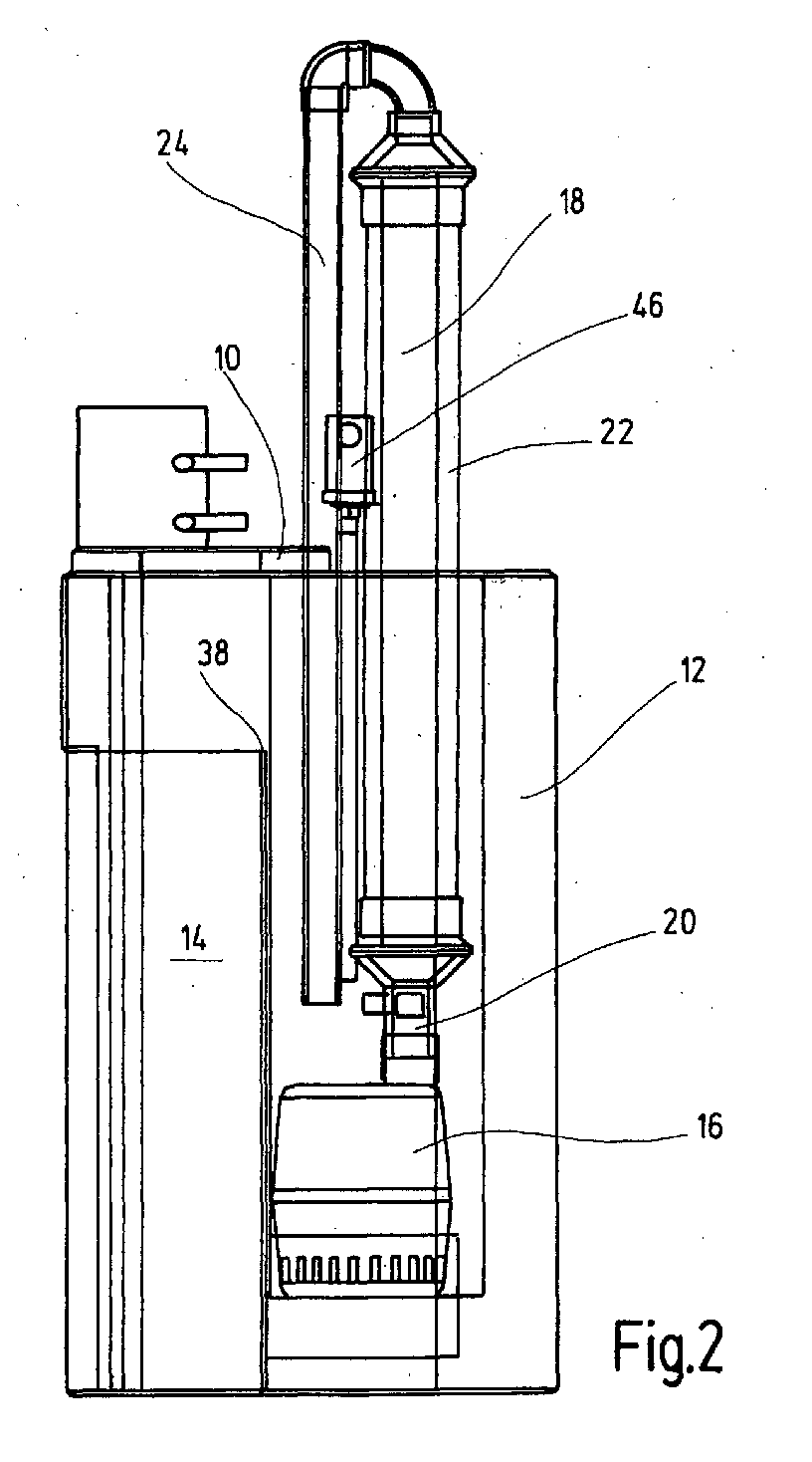
- the submersible pump is attached towards the bottom of the working chamber, the cross flow filter being housed in a housing In the longitudinal direction, about half of it protrudes from the working chamber. Consequently the unit takes up little space in the work chamber and the Cross-flow filter is accommodated in the device so that it is easily accessible from the outside.
- Device is the retentate of the cross flow filter via a return led into the working chamber and the resulting on the clean side of the filter Filtrate can be removed from the device via an outlet.
- the return for the retentate Has branch that opens into the rest chamber.
- the return and / or the branch are provided with adjustable throttles for adjusting the fluid flows. In this way there is a quasi-continuous operation with the device possible and in particular it is ensured that the working chamber cannot run empty, but continuously supplies the cross-flow filter, even if there is no condensate to be separated via the quiet chamber Fluid mixture is tracked.
- the free mouth of the branch into a independent overflow chamber opens into the working chamber, from whose Overflow the rest chamber is supplied. This ensures that the membrane module cannot idle when it is idle, which may be the case could damage the sensitive filtration medium.
- the rest chamber has an overflow for floating in particular Oil droplets on top, so that continuously the rest chamber can be freed from larger oil droplets.
- the working chamber for monitoring its level situation is provided with a state sensor, for example in the form of a float switch. This can also be ensured that it can not happen that the membrane module unintentionally idles.
- the device serves to separate a fluid mixture, in the present case Case in the form of an oil-water emulsion that goes through the entrance 10 is supplied to the device. With the oil-water emulsion mentioned it forms a fluid mixture of two immiscible phases, here oil and water.
- the device has a for this separation Working chamber 12 and a rest chamber 14. For receiving the Fluid mixture via the inlet 10 opens out with its one free one End in the upper region of the rest chamber 14.
- the rest chamber 14 also serves as a settling chamber for sedimenting components. The sedimented parts can Removed from the rest chamber 14 from time to time via a drain valve H1 become.
- the working chamber 12 has a motor-pump unit 16 as an assembly in the form of a commercially available submersible pump. Using submersible pumps, gray water is also pumped out of washing machines and drainage or rainwater is pumped. The flow rate is low per se and in the present exemplary embodiment is approximately 13 m 3 / h, this being completely sufficient for the present application.
- a cross-flow filter 18 is again provided which, as will be explained in more detail below, separates the fluid mixture into a filtrate and a retentate. As shown in FIG.
- the submersible pump formed from the motor pump unit 16 is attached to the underside of the working chamber 12 and the elongated cross-flow filter is placed on the pump outlet of the submersible pump with its filter inlet 20.
- the relevant structural unit consisting of cross-flow filter 18 and submersible pump 16 can simply be removed from the working chamber 12 from above and can also be used again after maintenance and / or replacement processes have been carried out.
- the overall separator device takes up little installation space and the units, such as pumps, cross-flow filters and the associated piping, which are otherwise arranged on a large industrial scale, are all integrated in the device.
- the actual cross-flow filter 18 is used to protect its filter materials received by a housing 22 and thereby in the longitudinal direction set up that the housing 22 in approximately half from the working chamber 12th protrudes. Furthermore, the housing 22 does not need to be used independently again to be attached but is secured by the motor pump unit 16 held.
- FIG. 1 further shows, the retentate of the crossflow filter 18 fed back into the working chamber 12 via a return 24.
- How 2 shows, in particular, the free end of the fluid-carrying end Return 24 above the submersible pump 16 into the working chamber 12.
- the clean side 26 of the cross flow filter 18, however, opens out over a Exit 28 out of the device.
- the relevant exit 28 is intended for the removal of the filtrate, here in the form of pure water.
- the return 24 for the retentate points above the crossflow filter 18 a branch 30 so that part of the retentate stream branches off does not get into the working chamber 12, but again into the rest chamber 30, in which there are small-volume oil droplets and contaminants can settle on the ground. In this respect, concentration processes avoided over the retentate opening into the working chamber 12.
- the fluid flows are in the return 24 and in the branch 30 chokes 32 switched, which are particularly adjustable.
- the free mouth of the junction 30 opens into an independent Overflow chamber 34, which is arranged in the rest chamber 14 and from whose overflow 36 the rest chamber 14 is supplied.
- the passing one Overflow 36 is arranged somewhat higher than the other overflow 38, through which the rest chamber 14, the working chamber 12 with the one to be separated Fluid mixture supplied.
- the rest chamber 14 a third overflow 40 in the manner of a skimming overflow so that especially large-volume oil droplets 42 that are on the top of the Float fluid mixture in the rest chamber 14, from the rest chamber 14 can be discharged to the outside.
- an oil overflow with outlet 44 available.
- the working chamber 12 for monitoring its level situation with a condition sensor is provided in the form of a monitoring device 46 with float body (not shown). Furthermore, the Working chamber 12 has a drain valve H2 on its underside from time to time free the container from sedimenting components to be able to.
- the condensate is in the form of an oil-water suspension via the input 10 fed.
- the rest chamber 14 fills up to the further overflow 38 the fluid mixture enters the working chamber 12.
- the motor - pump unit (submersible pump) 16 is switched on, the the fluid mixture introduced into it via the filter inlet 20 Cross flow filter 18 supplied and this takes a division of the fluid mixture into a retentate and a filtrate.
- the one consisting of pure water Filtrate is on the clean side 26 of the cross flow filter 18 and Exit 28 transported away from the device.
- the one concentrated with oil droplets Retentate is returned via the return 24 to the working chamber 12 promoted.
- the retentate 24 is circulated in the Working chamber 12 reached.
- a branch 30 opens and becomes part of the retentate stream returned to the rest chamber 14 in an independent overflow chamber 34.
- the overflow chamber 34 is filled, the corresponding one Retentate stream discharged via the overflow 36 into the other rest chamber.
Landscapes
- Water Supply & Treatment (AREA)
- Engineering & Computer Science (AREA)
- Chemical & Material Sciences (AREA)
- Chemical Kinetics & Catalysis (AREA)
- Thermal Sciences (AREA)
- Physics & Mathematics (AREA)
- Environmental & Geological Engineering (AREA)
- Organic Chemistry (AREA)
- Life Sciences & Earth Sciences (AREA)
- Hydrology & Water Resources (AREA)
- Structures Of Non-Positive Displacement Pumps (AREA)
- Removal Of Floating Material (AREA)
- Details Of Reciprocating Pumps (AREA)
- Fluid-Pressure Circuits (AREA)
- Separation Using Semi-Permeable Membranes (AREA)
- External Artificial Organs (AREA)
Abstract
Description
- Fig.1
- in der Art einer Schaltdarstellung die wichtigsten Komponenten der Vorrichtung und die
- Fig.2
- eine seitliche Ansicht auf die Vorrichtung nach der Fig.1.
Claims (9)
- Vorrichtung zum Auftrennen eines Fluidgemisches in mindestens zwei seiner Bestandteile mit einer Arbeitskammer (12) und einer Ruhekammer (14), die der Aufnahme des Fluidgemisches sowie von abgesetzten Bestandteilen desselben dient und aus der mittels einer Motor - Pumpeneinheit (16) für das Durchführen einer Filtration mittels eines Querstromfilters (18) das Fluidgemisch in die Arbeitskammer (12) gelangt, dadurch gekennzeichnet, daß die Motor - Pumpeneinheit (16) aus einer Tauchpumpe gebildet ist, die zusammen mit dem Querstromfilter (18) als Baueinheit in der Arbeitskammer (12) aufgenommen ist.
- Vorrichtung nach Anspruch 1, dadurch gekennzeichnet, daß die Tauchpumpe (16) in Richtung des Bodens der Arbeitskammer (12) befestigt ist und daß der Querstromfilter (18) von einem Gehäuse (22) aufgenommen in Längsrichtung aufgestellt in etwa hälftig aus der Arbeitskammer (12) ragt.
- Vorrichtung nach Anspruch 1 oder 2, dadurch gekennzeichnet, daß das Retentat des Querstromfilters (18) über eine Rückführung (24) in die Arbeitskammer (12) gelangt und daß auf der Reinseite (26) des Querstromfilters (18) über einen Ausgang (28) das Filtrat aus der Vorrichtung abführbar ist.
- Vorrichtung nach Anspruch 3, dadurch gekennzeichnet, daß als Fluidgemisch eine Emulsion von Wasser und Öl der Ruhekammer (14) zuführbar ist, daß das Filtrat aus reinem Wasser besteht und daß das Retentat in aufkonzentrierter Form Ölbestandteile aufweist.
- Vorrichtung nach Anspruch 3 oder 4, dadurch gekennzeichnet, daß die Rückführung (24) für das Retentat eine Abzweigung (30) aufweist, die in die Ruhekammer (14) mündet.
- Vorrichtung nach Anspruch 5, dadurch gekennzeichnet, daß die Rückführung (24) und/oder die Abzweigung (30) zum Einstellen der Fluidströme mit einstellbaren Drosseln (32) versehen sind.
- Vorrichtung nach Anspruch 5 oder 6, dadurch gekennzeichnet, daß die freie Mündung der Abzweigung (30) in eine eigenständige Überlaufkammer (34) in der Ruhekammer (14) mündet, aus deren Überlauf (36) die Ruhekammer (14) versorgt ist.
- Vorrichtung nach einem der Ansprüche 1 bis 7, dadurch gekennzeichnet, daß die Ruhekammer (14) einen Überlauf (40) für insbesondere aufschwimmende Öltröpfchen an ihrer Oberseite aufweist.
- Vorrichtung nach einem der Ansprüche 1 bis 8, dadurch gekennzeichnet, daß die Arbeitskammer (12) für die Überwachung ihrer Füllstandssituation mit einem Zustandssensor (46) versehen ist.
Applications Claiming Priority (2)
| Application Number | Priority Date | Filing Date | Title |
|---|---|---|---|
| DE10135420A DE10135420A1 (de) | 2001-07-20 | 2001-07-20 | Vorrichtung zum Auftrennen eines Fluidgemisches |
| DE10135420 | 2001-07-20 |
Publications (3)
| Publication Number | Publication Date |
|---|---|
| EP1277509A2 true EP1277509A2 (de) | 2003-01-22 |
| EP1277509A3 EP1277509A3 (de) | 2003-05-02 |
| EP1277509B1 EP1277509B1 (de) | 2005-10-26 |
Family
ID=7692516
Family Applications (1)
| Application Number | Title | Priority Date | Filing Date |
|---|---|---|---|
| EP02015823A Expired - Lifetime EP1277509B1 (de) | 2001-07-20 | 2002-07-16 | Vorrichtung zum Auftrennen eines Fluidgemisches |
Country Status (3)
| Country | Link |
|---|---|
| EP (1) | EP1277509B1 (de) |
| AT (1) | ATE307662T1 (de) |
| DE (2) | DE10135420A1 (de) |
Families Citing this family (1)
| Publication number | Priority date | Publication date | Assignee | Title |
|---|---|---|---|---|
| DE102017002080A1 (de) | 2017-03-04 | 2018-09-06 | Hydac Filter Systems Gmbh | Vorrichtung zur Entgasung von fließfähigen Fluiden |
Family Cites Families (7)
| Publication number | Priority date | Publication date | Assignee | Title |
|---|---|---|---|---|
| DE4209588C2 (de) * | 1992-03-25 | 1995-02-02 | Guetling Gmbh | Ölabscheider mit integrierter Mikrofiltrations-Einrichtung und Verfahren zu ihrer Reinigung |
| DE4215294C1 (de) * | 1992-03-25 | 1993-06-03 | Guetling Gmbh, 7012 Fellbach, De | |
| JPH0790151B2 (ja) * | 1992-10-28 | 1995-10-04 | ベスト工業株式会社 | 投げ込み式固液分離装置 |
| AT398069B (de) * | 1992-12-17 | 1994-09-26 | Hydrocleaner Produktions Und H | Gerät zur reinigung von feinteilige abfall- bzw. schadstoffphasen enthaltenden wässerigen phasen |
| DE19508296A1 (de) * | 1995-03-09 | 1996-09-12 | Hydac Filtertechnik Gmbh | Verfahren und Vorrichtung zur Phasenseparation |
| DE29611811U1 (de) * | 1996-07-06 | 1996-09-12 | SCHÜTT GmbH & Co. Umwelt Engineering KG, 36169 Rasdorf | Filtrationsanlage |
| DE19753326A1 (de) * | 1997-01-29 | 1998-07-30 | Berthold Guender | Verfahren und Vorrichtung zur biologischen Reinigung von Abwässern |
-
2001
- 2001-07-20 DE DE10135420A patent/DE10135420A1/de not_active Withdrawn
-
2002
- 2002-07-16 AT AT02015823T patent/ATE307662T1/de not_active IP Right Cessation
- 2002-07-16 DE DE50204658T patent/DE50204658D1/de not_active Expired - Fee Related
- 2002-07-16 EP EP02015823A patent/EP1277509B1/de not_active Expired - Lifetime
Also Published As
| Publication number | Publication date |
|---|---|
| DE10135420A1 (de) | 2003-02-06 |
| ATE307662T1 (de) | 2005-11-15 |
| EP1277509A3 (de) | 2003-05-02 |
| DE50204658D1 (de) | 2005-12-01 |
| EP1277509B1 (de) | 2005-10-26 |
Similar Documents
| Publication | Publication Date | Title |
|---|---|---|
| DE3538843C2 (de) | Vorrichtung zur kontinuierlichen Trennung von flüssigen Gemischen | |
| DE1611158C3 (de) | Filtereinrichtung | |
| DE1517394B2 (de) | Vorrichtung zur Reinigung von Wasser | |
| DE2743963A1 (de) | Vorrichtung zum reinigen von verschmutztem wasser | |
| DE4231837A1 (de) | Verfahren und Anlage zum Reinigen von ölverschmutztem und emulgiertem Bilgewasser auf Schiffen | |
| DE10246540B4 (de) | Vorrichtung zur Reinigung von Prozessgas einer Reflowlötanlage | |
| EP0355633B1 (de) | Vorrichtung zum Aufbereiten der Bearbeitungsflüssigkeit einer Elektroerosionsmaschine | |
| EP1832333A1 (de) | Verfahren zur Wiedergewinnung von verunreinigten Fluiden | |
| DE2247240A1 (de) | Flotationsanlage | |
| EP0569841B1 (de) | Vorrichtung zum Austragen von Wachspartikeln aus Umwälzwasser von Spritzkabinen | |
| DE2353469B2 (de) | Verfahren zur aufbereitung eines lackwasser-gemisches in lackieranlagen | |
| EP1277509B1 (de) | Vorrichtung zum Auftrennen eines Fluidgemisches | |
| DE4407343A1 (de) | Vorrichtung zum Abscheiden von Partikeln mit fester Konsistenz aus einer Flüssigkeit | |
| DE3540508C2 (de) | ||
| WO1993011846A1 (de) | Verfahren und einrichtung zur aufarbeitung von öl-wasser-emulsionen | |
| DE2736691C2 (de) | Vorrichtung zur Aufbereitung von Öl-Wasser-Emulsionen | |
| EP0730894B1 (de) | Verfahren und Vorrichtung zur Phasenseparation | |
| DE4033223A1 (de) | Vorrichtung zur reinigung von wasser | |
| DE19635005A1 (de) | Verfahren zum Aufbereiten von verunreinigtem Abwasser und Vorrichtung zu dessen Durchführung | |
| DE2743055A1 (de) | Einrichtung zur reinigung von schmier- und/oder kuehlemulsionen | |
| DE9203968U1 (de) | Ölabscheider mit integrierter Mikrofiltrations-Einrichtung | |
| DE9310027U1 (de) | Vorrichtung zum Reinigen von Abwässern | |
| DE9313340U1 (de) | Trennvorrichtung zum Abscheiden und/oder Absetzen von Flüssigkeiten aus einer Suspension, Emulsion o. dgl. | |
| DE102005035044A1 (de) | Verfahren zum Rückspülen von Kapillarmembranen einer Membrananlage | |
| DE20120288U1 (de) | Vorrichtung zur Aufbereitung von Wasser mittels Filtration |
Legal Events
| Date | Code | Title | Description |
|---|---|---|---|
| PUAI | Public reference made under article 153(3) epc to a published international application that has entered the european phase |
Free format text: ORIGINAL CODE: 0009012 |
|
| AK | Designated contracting states |
Kind code of ref document: A2 Designated state(s): AT BE BG CH CY CZ DE DK EE ES FI FR GB GR IE IT LI LU MC NL PT SE SK TR |
|
| AX | Request for extension of the european patent |
Free format text: AL;LT;LV;MK;RO;SI |
|
| PUAL | Search report despatched |
Free format text: ORIGINAL CODE: 0009013 |
|
| AK | Designated contracting states |
Designated state(s): AT BE BG CH CY CZ DE DK EE ES FI FR GB GR IE IT LI LU MC NL PT SE SK TR |
|
| AX | Request for extension of the european patent |
Extension state: AL LT LV MK RO SI |
|
| RIC1 | Information provided on ipc code assigned before grant |
Ipc: 7C 10M 175/06 B Ipc: 7C 02F 1/44 B Ipc: 7B 01D 61/18 A Ipc: 7B 01D 17/02 B Ipc: 7B 01D 61/14 B |
|
| 17P | Request for examination filed |
Effective date: 20030616 |
|
| AKX | Designation fees paid |
Designated state(s): AT BE BG CH CY CZ DE DK EE ES FI FR GB GR IE IT LI LU MC NL PT SE SK TR |
|
| 17Q | First examination report despatched |
Effective date: 20040628 |
|
| GRAP | Despatch of communication of intention to grant a patent |
Free format text: ORIGINAL CODE: EPIDOSNIGR1 |
|
| GRAS | Grant fee paid |
Free format text: ORIGINAL CODE: EPIDOSNIGR3 |
|
| GRAA | (expected) grant |
Free format text: ORIGINAL CODE: 0009210 |
|
| AK | Designated contracting states |
Kind code of ref document: B1 Designated state(s): AT BE BG CH CY CZ DE DK EE ES FI FR GB GR IE IT LI LU MC NL PT SE SK TR |
|
| PG25 | Lapsed in a contracting state [announced via postgrant information from national office to epo] |
Ref country code: FI Free format text: LAPSE BECAUSE OF FAILURE TO SUBMIT A TRANSLATION OF THE DESCRIPTION OR TO PAY THE FEE WITHIN THE PRESCRIBED TIME-LIMIT Effective date: 20051026 Ref country code: IE Free format text: LAPSE BECAUSE OF FAILURE TO SUBMIT A TRANSLATION OF THE DESCRIPTION OR TO PAY THE FEE WITHIN THE PRESCRIBED TIME-LIMIT Effective date: 20051026 Ref country code: NL Free format text: LAPSE BECAUSE OF FAILURE TO SUBMIT A TRANSLATION OF THE DESCRIPTION OR TO PAY THE FEE WITHIN THE PRESCRIBED TIME-LIMIT Effective date: 20051026 Ref country code: CZ Free format text: LAPSE BECAUSE OF FAILURE TO SUBMIT A TRANSLATION OF THE DESCRIPTION OR TO PAY THE FEE WITHIN THE PRESCRIBED TIME-LIMIT Effective date: 20051026 Ref country code: SK Free format text: LAPSE BECAUSE OF FAILURE TO SUBMIT A TRANSLATION OF THE DESCRIPTION OR TO PAY THE FEE WITHIN THE PRESCRIBED TIME-LIMIT Effective date: 20051026 |
|
| REG | Reference to a national code |
Ref country code: GB Ref legal event code: FG4D Free format text: NOT ENGLISH |
|
| REG | Reference to a national code |
Ref country code: CH Ref legal event code: EP |
|
| GBT | Gb: translation of ep patent filed (gb section 77(6)(a)/1977) |
Effective date: 20051026 |
|
| REG | Reference to a national code |
Ref country code: IE Ref legal event code: FG4D Free format text: LANGUAGE OF EP DOCUMENT: GERMAN |
|
| REF | Corresponds to: |
Ref document number: 50204658 Country of ref document: DE Date of ref document: 20051201 Kind code of ref document: P |
|
| PG25 | Lapsed in a contracting state [announced via postgrant information from national office to epo] |
Ref country code: DK Free format text: LAPSE BECAUSE OF FAILURE TO SUBMIT A TRANSLATION OF THE DESCRIPTION OR TO PAY THE FEE WITHIN THE PRESCRIBED TIME-LIMIT Effective date: 20060126 Ref country code: SE Free format text: LAPSE BECAUSE OF FAILURE TO SUBMIT A TRANSLATION OF THE DESCRIPTION OR TO PAY THE FEE WITHIN THE PRESCRIBED TIME-LIMIT Effective date: 20060126 Ref country code: BG Free format text: LAPSE BECAUSE OF FAILURE TO SUBMIT A TRANSLATION OF THE DESCRIPTION OR TO PAY THE FEE WITHIN THE PRESCRIBED TIME-LIMIT Effective date: 20060126 Ref country code: GR Free format text: LAPSE BECAUSE OF FAILURE TO SUBMIT A TRANSLATION OF THE DESCRIPTION OR TO PAY THE FEE WITHIN THE PRESCRIBED TIME-LIMIT Effective date: 20060126 |
|
| PG25 | Lapsed in a contracting state [announced via postgrant information from national office to epo] |
Ref country code: ES Free format text: LAPSE BECAUSE OF FAILURE TO SUBMIT A TRANSLATION OF THE DESCRIPTION OR TO PAY THE FEE WITHIN THE PRESCRIBED TIME-LIMIT Effective date: 20060206 |
|
| PG25 | Lapsed in a contracting state [announced via postgrant information from national office to epo] |
Ref country code: PT Free format text: LAPSE BECAUSE OF FAILURE TO SUBMIT A TRANSLATION OF THE DESCRIPTION OR TO PAY THE FEE WITHIN THE PRESCRIBED TIME-LIMIT Effective date: 20060327 |
|
| NLV1 | Nl: lapsed or annulled due to failure to fulfill the requirements of art. 29p and 29m of the patents act | ||
| REG | Reference to a national code |
Ref country code: IE Ref legal event code: FD4D |
|
| ET | Fr: translation filed | ||
| PG25 | Lapsed in a contracting state [announced via postgrant information from national office to epo] |
Ref country code: GB Free format text: LAPSE BECAUSE OF NON-PAYMENT OF DUE FEES Effective date: 20060716 |
|
| PG25 | Lapsed in a contracting state [announced via postgrant information from national office to epo] |
Ref country code: LI Free format text: LAPSE BECAUSE OF NON-PAYMENT OF DUE FEES Effective date: 20060731 Ref country code: MC Free format text: LAPSE BECAUSE OF NON-PAYMENT OF DUE FEES Effective date: 20060731 Ref country code: CH Free format text: LAPSE BECAUSE OF NON-PAYMENT OF DUE FEES Effective date: 20060731 Ref country code: BE Free format text: LAPSE BECAUSE OF NON-PAYMENT OF DUE FEES Effective date: 20060731 |
|
| PGFP | Annual fee paid to national office [announced via postgrant information from national office to epo] |
Ref country code: IT Payment date: 20060731 Year of fee payment: 5 |
|
| PLBE | No opposition filed within time limit |
Free format text: ORIGINAL CODE: 0009261 |
|
| STAA | Information on the status of an ep patent application or granted ep patent |
Free format text: STATUS: NO OPPOSITION FILED WITHIN TIME LIMIT |
|
| 26N | No opposition filed |
Effective date: 20060727 |
|
| REG | Reference to a national code |
Ref country code: CH Ref legal event code: PL |
|
| GBPC | Gb: european patent ceased through non-payment of renewal fee |
Effective date: 20060716 |
|
| REG | Reference to a national code |
Ref country code: FR Ref legal event code: ST Effective date: 20070330 |
|
| PGFP | Annual fee paid to national office [announced via postgrant information from national office to epo] |
Ref country code: DE Payment date: 20070712 Year of fee payment: 6 |
|
| PG25 | Lapsed in a contracting state [announced via postgrant information from national office to epo] |
Ref country code: AT Free format text: LAPSE BECAUSE OF NON-PAYMENT OF DUE FEES Effective date: 20060716 |
|
| BERE | Be: lapsed |
Owner name: HYDAC PROCESS TECHNOLOGY G.M.B.H. Effective date: 20060731 |
|
| PG25 | Lapsed in a contracting state [announced via postgrant information from national office to epo] |
Ref country code: FR Free format text: LAPSE BECAUSE OF NON-PAYMENT OF DUE FEES Effective date: 20060731 |
|
| PG25 | Lapsed in a contracting state [announced via postgrant information from national office to epo] |
Ref country code: EE Free format text: LAPSE BECAUSE OF FAILURE TO SUBMIT A TRANSLATION OF THE DESCRIPTION OR TO PAY THE FEE WITHIN THE PRESCRIBED TIME-LIMIT Effective date: 20051026 |
|
| PG25 | Lapsed in a contracting state [announced via postgrant information from national office to epo] |
Ref country code: LU Free format text: LAPSE BECAUSE OF NON-PAYMENT OF DUE FEES Effective date: 20060716 Ref country code: TR Free format text: LAPSE BECAUSE OF FAILURE TO SUBMIT A TRANSLATION OF THE DESCRIPTION OR TO PAY THE FEE WITHIN THE PRESCRIBED TIME-LIMIT Effective date: 20051026 |
|
| PG25 | Lapsed in a contracting state [announced via postgrant information from national office to epo] |
Ref country code: CY Free format text: LAPSE BECAUSE OF FAILURE TO SUBMIT A TRANSLATION OF THE DESCRIPTION OR TO PAY THE FEE WITHIN THE PRESCRIBED TIME-LIMIT Effective date: 20051026 |
|
| PG25 | Lapsed in a contracting state [announced via postgrant information from national office to epo] |
Ref country code: DE Free format text: LAPSE BECAUSE OF NON-PAYMENT OF DUE FEES Effective date: 20090203 |
|
| PG25 | Lapsed in a contracting state [announced via postgrant information from national office to epo] |
Ref country code: IT Free format text: LAPSE BECAUSE OF NON-PAYMENT OF DUE FEES Effective date: 20070716 |