EP1277659A2 - Verfahren zum Transportieren von sehr grossen Reifen - Google Patents
Verfahren zum Transportieren von sehr grossen Reifen Download PDFInfo
- Publication number
- EP1277659A2 EP1277659A2 EP02100800A EP02100800A EP1277659A2 EP 1277659 A2 EP1277659 A2 EP 1277659A2 EP 02100800 A EP02100800 A EP 02100800A EP 02100800 A EP02100800 A EP 02100800A EP 1277659 A2 EP1277659 A2 EP 1277659A2
- Authority
- EP
- European Patent Office
- Prior art keywords
- tire
- carcass
- tread
- tires
- tread belt
- Prior art date
- Legal status (The legal status is an assumption and is not a legal conclusion. Google has not performed a legal analysis and makes no representation as to the accuracy of the status listed.)
- Granted
Links
- 238000000034 method Methods 0.000 title claims abstract description 33
- 239000011324 bead Substances 0.000 claims description 26
- 238000003825 pressing Methods 0.000 claims description 2
- 238000003860 storage Methods 0.000 abstract description 9
- 230000006835 compression Effects 0.000 description 27
- 238000007906 compression Methods 0.000 description 27
- 238000010276 construction Methods 0.000 description 6
- 125000006850 spacer group Chemical group 0.000 description 5
- 230000003014 reinforcing effect Effects 0.000 description 4
- 230000001012 protector Effects 0.000 description 3
- IJGRMHOSHXDMSA-UHFFFAOYSA-N Atomic nitrogen Chemical compound N#N IJGRMHOSHXDMSA-UHFFFAOYSA-N 0.000 description 2
- 230000009286 beneficial effect Effects 0.000 description 2
- 239000004744 fabric Substances 0.000 description 2
- 239000000463 material Substances 0.000 description 2
- 238000005065 mining Methods 0.000 description 2
- 230000002787 reinforcement Effects 0.000 description 2
- 241000254043 Melolonthinae Species 0.000 description 1
- 229910000831 Steel Inorganic materials 0.000 description 1
- 230000000712 assembly Effects 0.000 description 1
- 238000000429 assembly Methods 0.000 description 1
- 238000005452 bending Methods 0.000 description 1
- 238000005520 cutting process Methods 0.000 description 1
- 230000001419 dependent effect Effects 0.000 description 1
- 230000007774 longterm Effects 0.000 description 1
- 238000004519 manufacturing process Methods 0.000 description 1
- 239000002184 metal Substances 0.000 description 1
- 239000000203 mixture Substances 0.000 description 1
- 208000001491 myopia Diseases 0.000 description 1
- 229910052757 nitrogen Inorganic materials 0.000 description 1
- 230000008520 organization Effects 0.000 description 1
- 210000000006 pectoral fin Anatomy 0.000 description 1
- 230000035515 penetration Effects 0.000 description 1
- 230000002028 premature Effects 0.000 description 1
- 239000011435 rock Substances 0.000 description 1
- 238000007789 sealing Methods 0.000 description 1
- 239000010959 steel Substances 0.000 description 1
Images


Classifications
-
- B—PERFORMING OPERATIONS; TRANSPORTING
- B65—CONVEYING; PACKING; STORING; HANDLING THIN OR FILAMENTARY MATERIAL
- B65D—CONTAINERS FOR STORAGE OR TRANSPORT OF ARTICLES OR MATERIALS, e.g. BAGS, BARRELS, BOTTLES, BOXES, CANS, CARTONS, CRATES, DRUMS, JARS, TANKS, HOPPERS, FORWARDING CONTAINERS; ACCESSORIES, CLOSURES, OR FITTINGS THEREFOR; PACKAGING ELEMENTS; PACKAGES
- B65D85/00—Containers, packaging elements or packages, specially adapted for particular articles or materials
- B65D85/02—Containers, packaging elements or packages, specially adapted for particular articles or materials for annular articles
- B65D85/06—Containers, packaging elements or packages, specially adapted for particular articles or materials for annular articles for tyres
-
- B—PERFORMING OPERATIONS; TRANSPORTING
- B65—CONVEYING; PACKING; STORING; HANDLING THIN OR FILAMENTARY MATERIAL
- B65G—TRANSPORT OR STORAGE DEVICES, e.g. CONVEYORS FOR LOADING OR TIPPING, SHOP CONVEYOR SYSTEMS OR PNEUMATIC TUBE CONVEYORS
- B65G2201/00—Indexing codes relating to handling devices, e.g. conveyors, characterised by the type of product or load being conveyed or handled
- B65G2201/02—Articles
- B65G2201/0273—Tires
Definitions
- This invention relates to methods for shipping pneumatic tires typically for use with very large vehicles such as earthmoving vehicles.
- the pneumatic tires which are the subject of the method of the present invention, are very large tires (greater than 120 inch or 3.05 m outside diameter (OD)) generally designed for use on very large vehicles, generally off-the-road (OTR) vehicles such as earthmovers and large-capacity mining trucks (e.g., 300 short tons or more).
- OTR off-the-road
- These very large tires and vehicles are generally utilized at long-term mining or construction sites such as rock quarries, mines, foundries, major tunnel/roadway construction, dams/dikes, and the like.
- the very large vehicles are generally too large to transport to the work site normally, and are therefore often shipped in pieces to the work site where the pieces are assembled/welded together for use.
- Another problem is storage of the very large tires at the work site. As tires become larger, more and more space is required for storage. Also, if operating conditions are particularly harsh, or if shipping of replacement tires "on demand" is not practical, then increased numbers of spares must be stocked, further increasing the storage space needed. Furthermore, some job sites require different tread designs for different operating conditions. For example, wide treads with deep cleats may be needed for muddy conditions. Given the time consuming nature of the existing tire-changing methods, changing tires to obtain optimum tread patterns is not always feasible.
- the present invention permits an even more efficient method of shipping such tires.
- the present invention relates to an improved method for shipping and storing very large pneumatic tires, which are used on very large vehicles such as earthmover vehicles.
- Very large tires of conventional construction are sometimes over 13 feet (4 meter) in height and approximately 8,000 pounds (3,628 kg) to 15,000 pounds (6,803 kg) in weight and proposed very large truck designs require even larger tires.
- the size and weight of the very large conventional tires presents significant problems in shipping, storage and tire changing.
- the method of shipping very large diameter tires having unrestrained diameters (OD) over 120 inches (3.05 meters) had the step of holding at least one diameteral size of the tire 10 in a compressed state thereby reducing the distance from the unrestrained diameter (OD) of over 120 inches to a maximum distance (H) or less as measured across at least two opposing diameteral sides of the tires.
- the compressed distance H being at or below standard widths for commercial trucking.
- the compressed state tire can be placed on a commercial standard width flat bed trailer or within a commercial standard size shipping container for shipment. If only one side of the tire is compressed the assembly may be shipped vertically allowing the compressed side to act as a base assuming the height is sufficiently small to allow bridge clearance. Alternately, the tires may be shipped horizontally laying on the sidewalls and stacked vertically.
- the tires may be restrained along two diametrically opposed sides thus compressing the encircled carcass across two sides.
- the tires can be shipped standing vertical and stacked horizontally assuming sufficient vertical clearance is maintained in most containers and closed trailers the vertical height is between 90 and 110 inches (229 and 279 cm) general while the width is 90 to 96 inches (229 and 279 cm) for standard width trailers and containers.
- the elongated oval shape means the longest dimension is increased by an amount at least as much as the amount of diametrical compression and in such a case the recommended way to ship the tire in the compressed state is to orient the elongated length in the lengthwise direction of the trailer or container whether shipped vertically or horizontally.
- the compression of the carcass is such that the elongated sides of the tread belt are substantially straight sided or convexly curved.
- the tread belt can be compressed beyond straight sided resulting in a somewhat figure bow tie shape.
- the amount of compression is recommended to be generally as small as needed to comply with the shipping constraints.
- the tire is compressed by holding four diametrical sides thereby reducing the opposite sides to form a substantially rectangular or square tire for shipping.
- the very large tires have a removable tread belt and the tread belt is shipped encircling the tire carcass.
- the removable tread belt is held in a compressed state for shipping, thereby having a significantly-reduced diameter for ease of shipping by using the tire carcass as deformable spacer.
- the deformable carcass spacer is provided for the compressed tread belt forming the tread belt into an elongated oval shape.
- the assembly of oval shaped tread belt encircling the compressed tire in a reduced dimensional state for shipping can create gaps between one or both ends of the elongated oval tread belt and the carcass.
- At least some of the tread belts are stored in a compressed state, thereby further reducing storage space requirements.
- Elements of the figures are typically numbered as follows. The most significant digits (hundreds) of the reference number correspond to the figure number. Elements of Figure 1 are typically numbered in the range of 10-199. Elements of Figure 2 are typically numbered in the range of 10-399. Similar elements throughout the drawings may be referred to by similar reference numerals. For example, the element 199 may be referred to individually as 199a, 199b, 199c, etc. Such relationships, if any, between similar elements in the same or different figures will become apparent throughout the specification, including, if applicable, in the claims and abstract.
- Bead means that part of the tire comprising an annular tensile member wrapped by the ply cords and shaped, with or without other reinforcement element such as flippers, chippers, apexes, toe guards and chafer, to fit the wheel rim.
- Belt or breaker reinforcing structure means at least two layers of plies of parallel cords, woven or unwoven, underlying the tread, unanchored to the bead, and having both left and right cord angles in the range from 17 degrees to 33 degrees with respect of the equatorial plane of the tire.
- “Bias ply tire” means a tire having a carcass with reinforcing cords in the carcass ply extending diagonally across the tire from bead core to bead core at about 25-50 angle with respect to the equatorial plane of the tire. Cords run at opposite angles in alternate layers.
- “Circumferential” means lines or directions extending along the perimeter of the surface of the annular tread perpendicular to the axial direction.
- Core means one of the reinforcement strands of which the plies in the tire are comprised.
- Equatorial plane means the plane perpendicular to the tire's axis of rotation and passing through the center of its tread.
- “Footprint” means the contact patch or area of contact of the tire tread with a flat surface under load and pressure.
- “Lateral” and “laterally” means lines or directions that are parallel to the axis of rotation of the tire (also “axial”).
- Normal inflation pressure refers to the specific design inflation pressure at a specific load assigned by the appropriate standards organization for the service condition for the tire.
- Ply means a continuous layer of rubber-coated parallel cords.
- Ring and radially means directions extending radially toward or away from the axis of rotation of the tire.
- Ring-ply tire means a belted or circumferentially-restricted pneumatic tire in which the ply cords which extend from bead to bead are laid at cord angles between 65 degrees and 90 degrees with respect to the equatorial plane of the tire.
- Zero-degree wires means at least one layer of parallel cords (usually metal wire), underlying the tread, unanchored to the bead, spiraling circumferentially around the tread, and having cord angles in the range from 9 degrees to 5 degrees with respect to the equatorial plane of the tire.
- One application of the method of this invention is used with a tread belt 12 and separate carcass 14 assembled to form a very large tire 10 (such as tires greater than 120 inches (3.05 meters) in diameter as sued on earthmover-type very large vehicles).
- the method is not dependent on a particular design for the removable tread belt 12 and matching carcass 14. Although a specific very large tire design is described herein below for illustrating the embodiment of this inventive method, the inventive method should not be limited to this particular tire design.
- Figure 1 illustrates a cross-section of a portion of a very large tread belt pneumatic tire 10 which in the specific embodiment illustrated is a size 70/68R63 earthmover tires.
- the size 70/68R63 tires has a 162 inch (411,42 cm) maximum inflated outside diameter (OD), a 70.0 inch (177.80 cm) maximum inflated width in the axial direction, and a nominal bead diameter of 63 inches (160 cm).
- the tread belt 12 has a thickness (t) of approximately 10 inches (254 cm), and a width of approximately 60 inches (152 cm).
- the assembled tire 10 weighs 16,000 pounds (7,256 kg), of which approximately 8,000 pounds (3,628 kg) are in the removable tread belt 12.
- the tire carcass 14 is typically inflated to a pressure of about 100 pounds per square inch (686 kPa) with air and sometimes with an air/nitrogen mixture.
- the very large tread belt pneumatic tire 10 includes a ground engaging, circumferentially extending tread belt 12 mounted on a radially reinforced, beaded tire carcass 14.
- the beaded tire carcass 14 generally includes a pair of tire sidewalls 16 extending radially inwardly form the outer circumferential surface 20 of the tire carcass 14 and terminating at a pair of bead wires 22.
- the sidewalls 16 each have an upper portion 16a in the shoulder region of the tire carcass 14 and radially outward of the maximum section width of the tire carcass 14, and a lower portion 16b, adjacent the bead wires 22, and radially inward of the maximum section width of the tire carcass 14.
- the carcass 14 generally contains at least one rubberized laminated ply layer 34 of tire cord fabric.
- the carcass 14 mounts on the wheel mounting rim 42, pneumatically sealing the area of the bead 22 against, and held in place by, the flange 35, which is generally removable from the rim 42 on wheels used for very large tires 10.
- An optional feature is generally included in removable tread belt tires 10 in order to assist in holding the removable tread belt 12 in place on the carcass 14.
- This optional feature illustrated in Figure 1, comprises a set of one or more grooves 78 and one or more lands 76 formed in the outer circumferential surface 20 of the carcass 14.
- the ground engaging, circumferentially extending tread belt 12 is removably mounted onto the tire carcass 14.
- the tire tread belt 12 comprises a tread portion 80, and at least one belt 82, 84, 86 and/or 88 (82-88) or set of zero-degree wires 90 which encircle the tire tread and are provided to restrict the radially outward growth of the tread belt 12.
- the placement and shape of the wires 90 and/or the belts 82-86, are the subject of other patents, and are not critical to the method of this invention.
- An optional feature of the tread belt 12 embodiment illustrated in Figure 1 comprises one or more annular lands 72 and one or more annular grooves 74 in the underside or inner circumferential surface 70 of the tread belt 12 the interlock with corresponding grooves 78 and lands 76of the tire carcass 14 to restrain the tread belt 12 from the lateral or axial movement with respect to the carcass 14.
- the present invention method of transporting very large tires can take advantage of width, length and vertical height limitations and enable tires otherwise too large for standard shipment to be able to fit within these restrictions.
- the present invention teaches the assembled tire 10 can be compressed to fit within either the vertical limitation or the width limitation of a standard size load and then shipped in the compressed state.
- the encircled carcass 14 and the tread belt 12 are compressed wherein the carcass 14 acts as a spacer for the tread belt 12 as shown in Figures 4A and 4B. Due to the fact that the tread belt 12 is free of the carcass 14 as the tire assembly is compressed means the non-compressed portions of the carcass 14 and the tread belt 12 can elongate.
- the cords in the carcass 14 limit the amount of expansion but the tread belt 12 can actually locally separate from the carcass 14 as shown creating gaps G between the carcass 14 and the tread belt 12.
- the percentage of compression may be more restricted or limited to prevent tire damage due to the higher strains placed on the belt edges.
- the present method of compressing these very large tires 10 can work in both the two-piece tires 10 or in a more conventional one-piece tire 10. Heretofore, and prior to the design of these very large tires it has been the practice to not compress the tires for fear of tire damage.
- the present invention describes several ways in which one or more portions of a tire can be compressed by applying pressure from the tread radially inwardly.
- the tire is compressed into various smaller dimensions when prepared for shipping.
- the tire 10 is radially compressed and held in a compressed state by one or more straps 210 (210a, 210b, 210c) made of steel or other suitable shipping strap material such as plastic, fabric, ropes or chains.
- straps 210 compress the tread 12 into the underlying carcass 14.
- the straps can be passed through the beads 22 and by applying a force the beads 22 and the tread 12 come closer together.
- a bead protector 310 can be used to prevent the strap from cutting into the beads 22.
- the bead protector 310 can occupy as much as 180 degrees of the bead circumference and thereby permit the defection and compression to occur over a sufficiently large area.
- the bead protector 310 preferably should overhang the beads to bulge apart to allow improved deflection.
- the compression of one side of the tire 10 creates a flat side to facilitate vertical shipment of the tires.
- the compressed tire is preferably strapped onto a bottom pallet 230 of dimensions suitable to support at least the entire footprint, the width W at least the flat-sided length Lf of the compressed tire 10.
- the pallet 230 is constructed by known techniques and of suitable, known pallet materials, and is designed to be able to sustain expected weights and shipping forces.
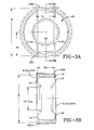
- Another method involves compressing the tread 12 in two diametrically opposed portions.
- the tire is compressed by applying a force cross the tread thereby flattening the underlying carcass as shown in the Figures 3A, 3B, 4A and 4C.
- the advantage of this method is the carcass is deflected in two locations permitting the dimensional compression to be double that of the previous described method of Figures 2A and 2B.
- a top pallet 232 similar to the bottom pallet 230, is shown added about the compressed tread belt 12 and held in place by the straps 210a, 210b.
- the tread belt 12 is protected from the damage by contact with the straps 210a, 210b.
- Tires 10 compressed as shown have the bead portions 22 free to bulge out as the underlying carcass is compressed. This ability to bulge outwardly is natural unless restrained. This is believed beneficial to reduce some of the strain on the compressed carcass.
- the tires 10 can be stacked vertically by laying such tire horizontally onto the trailer. Alternatively the tires 10 may be aligned in rows sitting vertically. In either case the tires 10 are restrained and tied to the trailer for shipment.
- the tires 10 greater than 120 inches (305 cm) OD require a much higher percentage of compression. Accordingly the tires 10 with 185 inch (470 cm) OD require 75 inches (190.5 cm) of total deflection. Since the sidewall including the tread 12 and bead 22 are only 55 inches (140 cm) tall, the compression must be from at least two sides and even if shipped vertically a 110 inch (279 cm) dimension is permitted. It is appreciated higher vertical heights can be achieved if the trailer deck is lowered or the bridge clearances permit. Nevertheless, shipping horizontally is very compressed at the 102 in (259 cm) width constraint. Often times slightly larger widths may be permitted on flatbed trucks. In some cases a few inches overhang locally may be permitted, as is the case in tires of the 120 inch (305 cm) diameter size or less. However, as these tires get ever larger, the amount of tire overhang is too great to permit transport within standard size guidelines absent compression.
- the amount of compression in very large tires may be too great to permit compression as seen in the exemplary 185 inch (470 cm) OD sized giant tire.
- the 162 inch (411 cm) OD sized tire may be reaching a limit in compression for a single molded tire.
- the two piece tire however, has the capacity to achieve such massive amounts of compression due to the highly flexible underlying carcass 14 and the fact that the tread belt structure 100 is independent of the carcass 14.
Landscapes
- Engineering & Computer Science (AREA)
- Mechanical Engineering (AREA)
- Tires In General (AREA)
- Tyre Moulding (AREA)
- Processing And Handling Of Plastics And Other Materials For Molding In General (AREA)
- Loading Or Unloading Of Vehicles (AREA)
Applications Claiming Priority (2)
| Application Number | Priority Date | Filing Date | Title |
|---|---|---|---|
| US909366 | 2001-07-19 | ||
| US09/909,366 US6532718B2 (en) | 2001-07-19 | 2001-07-19 | Method of shipping very large tires |
Publications (3)
| Publication Number | Publication Date |
|---|---|
| EP1277659A2 true EP1277659A2 (de) | 2003-01-22 |
| EP1277659A3 EP1277659A3 (de) | 2003-04-16 |
| EP1277659B1 EP1277659B1 (de) | 2006-02-01 |
Family
ID=25427118
Family Applications (1)
| Application Number | Title | Priority Date | Filing Date |
|---|---|---|---|
| EP02100800A Expired - Lifetime EP1277659B1 (de) | 2001-07-19 | 2002-07-11 | Verfahren zum Transportieren von sehr grossen Reifen |
Country Status (8)
| Country | Link |
|---|---|
| US (1) | US6532718B2 (de) |
| EP (1) | EP1277659B1 (de) |
| JP (1) | JP2003072956A (de) |
| AU (1) | AU2002300015B2 (de) |
| BR (1) | BR0202680A (de) |
| CA (1) | CA2392781A1 (de) |
| DE (1) | DE60208973T2 (de) |
| ZA (1) | ZA200205757B (de) |
Families Citing this family (8)
| Publication number | Priority date | Publication date | Assignee | Title |
|---|---|---|---|---|
| WO2002054978A2 (en) * | 1999-08-18 | 2002-07-18 | Intrinsic Orthopedics Inc | Devices and method for nucleus pulposus augmentation and retention |
| US6883520B2 (en) * | 1999-08-18 | 2005-04-26 | Intrinsic Therapeutics, Inc. | Methods and apparatus for dynamically stable spinal implant |
| US7048484B2 (en) * | 2004-09-23 | 2006-05-23 | The Goodyear Tire & Rubber Company | Method of shipping and storing removable tread belts for very large tires |
| US7207366B2 (en) * | 2004-12-22 | 2007-04-24 | The Goodyear Tire & Rubber Company | Two-piece tire |
| KR100845387B1 (ko) * | 2007-06-19 | 2008-07-09 | 금호타이어 주식회사 | 타이어의 플랫 스폿 모사 시험기 |
| KR100992391B1 (ko) | 2008-10-30 | 2010-11-08 | 한국타이어 주식회사 | 자동차용 타이어의 플랫 스팟 방지 장치 |
| CA2763798C (en) * | 2009-06-19 | 2016-02-09 | Wabash National, L.P. | Semi-trailer for transporting circular objects |
| US9850080B1 (en) * | 2017-05-15 | 2017-12-26 | Cascade Corporation | Load handler for loading and unloading tall resilient unitary loads in height-restricting containers |
Citations (7)
| Publication number | Priority date | Publication date | Assignee | Title |
|---|---|---|---|---|
| US3087526A (en) | 1960-08-02 | 1963-04-30 | Pirelli | Pneumatic tire with separate tread rings |
| US3224482A (en) | 1963-02-05 | 1965-12-21 | Pirelli | Removable tread tires |
| US3897814A (en) | 1974-03-11 | 1975-08-05 | Caterpillar Tractor Co | Tire tread belt |
| GB2073109A (en) | 1980-02-28 | 1981-10-14 | Goodyear Tire & Rubber | Replaceable tread tyres |
| US4351380A (en) | 1980-12-29 | 1982-09-28 | The Goodyear Tire & Rubber Company | Track belt assembly |
| US5034807A (en) | 1986-03-10 | 1991-07-23 | Kohorn H Von | System for evaluation and rewarding of responses and predictions |
| US6324814B1 (en) | 2000-03-02 | 2001-12-04 | The Goodyear Tire & Rubber Company | Method of shipping very large tires |
Family Cites Families (20)
| Publication number | Priority date | Publication date | Assignee | Title |
|---|---|---|---|---|
| US2659484A (en) * | 1950-06-01 | 1953-11-17 | Union Steel Prod Co | Device for packaging tire casings and the tire casing assemblies |
| US2690253A (en) * | 1951-02-19 | 1954-09-28 | Paul L Francois | Packaged endless drive belt |
| US3012663A (en) * | 1959-11-02 | 1961-12-12 | Virgil F Thorne | Automobile tire shipping package and tire retaining pallet therefor |
| US3578052A (en) | 1968-09-19 | 1971-05-11 | Aivars V Petersons | Replaceable tread on an expanding diameter car carcass tire |
| US3619966A (en) | 1970-05-05 | 1971-11-16 | Dayco Corp | Apparatus for and method of packaging endless belts |
| US3850295A (en) | 1971-10-12 | 1974-11-26 | B Black | Tire shipping and storage structure |
| US3822526A (en) | 1973-05-14 | 1974-07-09 | B Black | Tire compressing and handling apparatus |
| US3963066A (en) * | 1975-03-25 | 1976-06-15 | Schwartz Kenneth P | Reversible replaceable tread tire |
| US3942637A (en) * | 1975-04-28 | 1976-03-09 | Minnesota Mining & Manufacturing Company | Package for endless belts |
| US4150745A (en) * | 1978-04-03 | 1979-04-24 | The Goodyear Tire & Rubber Company | Belt packaging tray |
| US4314597A (en) * | 1978-09-26 | 1982-02-09 | Iowa Mold Tooling Co., Inc. | Tire mounting and demounting apparatus and method |
| US4550827A (en) | 1983-04-21 | 1985-11-05 | The Goodyear Tire & Rubber Company | Tire packaging |
| FR2555943B1 (fr) * | 1983-12-03 | 1988-04-29 | Daiko Kk | Dispositif protecteur de talon de pneumatique |
| US4678084A (en) * | 1985-12-17 | 1987-07-07 | United States Supply Company | Shipping container for packaging endless belts for transportation or storage |
| US5056662A (en) * | 1990-06-26 | 1991-10-15 | Minnesota Mining And Manufacturing Company | Wide abrasive belt carton |
| GB9016089D0 (en) | 1990-07-23 | 1990-09-05 | Bluteau Yves | Used tire storing device |
| US5201427A (en) | 1992-02-06 | 1993-04-13 | Mdr Cartage, Inc. | Rack for stacking and maintaining stacked articles under compression |
| WO1996005981A1 (en) * | 1994-08-18 | 1996-02-29 | Hiroyuki Minakami | Wheel fixing device, pallet/truck and wheel fixing method, automatic wheel fixing device and mode interchange |
| US5544578A (en) | 1994-09-01 | 1996-08-13 | Keller; Michael | Tire load compressor |
| US5584622A (en) * | 1995-03-10 | 1996-12-17 | Dickerson, Sr.; Donald L. | Tie down device for vehicle |
-
2001
- 2001-07-19 US US09/909,366 patent/US6532718B2/en not_active Expired - Fee Related
-
2002
- 2002-07-08 AU AU2002300015A patent/AU2002300015B2/en not_active Ceased
- 2002-07-09 CA CA002392781A patent/CA2392781A1/en not_active Abandoned
- 2002-07-11 BR BR0202680-5A patent/BR0202680A/pt not_active Application Discontinuation
- 2002-07-11 DE DE60208973T patent/DE60208973T2/de not_active Expired - Fee Related
- 2002-07-11 EP EP02100800A patent/EP1277659B1/de not_active Expired - Lifetime
- 2002-07-18 ZA ZA200205757A patent/ZA200205757B/xx unknown
- 2002-07-18 JP JP2002209672A patent/JP2003072956A/ja active Pending
Patent Citations (7)
| Publication number | Priority date | Publication date | Assignee | Title |
|---|---|---|---|---|
| US3087526A (en) | 1960-08-02 | 1963-04-30 | Pirelli | Pneumatic tire with separate tread rings |
| US3224482A (en) | 1963-02-05 | 1965-12-21 | Pirelli | Removable tread tires |
| US3897814A (en) | 1974-03-11 | 1975-08-05 | Caterpillar Tractor Co | Tire tread belt |
| GB2073109A (en) | 1980-02-28 | 1981-10-14 | Goodyear Tire & Rubber | Replaceable tread tyres |
| US4351380A (en) | 1980-12-29 | 1982-09-28 | The Goodyear Tire & Rubber Company | Track belt assembly |
| US5034807A (en) | 1986-03-10 | 1991-07-23 | Kohorn H Von | System for evaluation and rewarding of responses and predictions |
| US6324814B1 (en) | 2000-03-02 | 2001-12-04 | The Goodyear Tire & Rubber Company | Method of shipping very large tires |
Also Published As
| Publication number | Publication date |
|---|---|
| EP1277659A3 (de) | 2003-04-16 |
| US20030014943A1 (en) | 2003-01-23 |
| JP2003072956A (ja) | 2003-03-12 |
| AU2002300015B2 (en) | 2006-11-23 |
| ZA200205757B (en) | 2003-03-27 |
| DE60208973T2 (de) | 2006-09-21 |
| BR0202680A (pt) | 2003-05-06 |
| DE60208973D1 (de) | 2006-04-13 |
| EP1277659B1 (de) | 2006-02-01 |
| US6532718B2 (en) | 2003-03-18 |
| CA2392781A1 (en) | 2003-01-19 |
Similar Documents
| Publication | Publication Date | Title |
|---|---|---|
| US7972550B2 (en) | Method of increasing the load capacity of a radial tire | |
| US20160052345A1 (en) | Heavy load vehicle tire | |
| AU783619B2 (en) | Two piece tire with improved tire tread belt and carcass | |
| EP1277659B1 (de) | Verfahren zum Transportieren von sehr grossen Reifen | |
| US6478387B1 (en) | Heavy duty dual tire assembly | |
| EP1129963B1 (de) | Verfahren zum Transportieren, Lagern und Wechseln von sehr grossen Reifen | |
| EP1019259B1 (de) | Reifen mit umgekehrter konfiguration des karkassenschichtenumschlages | |
| US6422280B1 (en) | Heavy duty tire with specified bead design | |
| US6352090B1 (en) | Tire with reversed carcass ply turnup configuration | |
| US7299841B2 (en) | Two piece tire with improved tire tread belt | |
| AU783727B2 (en) | Method of shipping storing and changing very large tires | |
| US7048484B2 (en) | Method of shipping and storing removable tread belts for very large tires | |
| RU2263584C2 (ru) | Способ транспортировки и замены очень больших пневматических шин | |
| AU2011203116B2 (en) | Method of increasing the load carrying capacity of a radial tyre | |
| AU3133397A (en) | Tire with removable tire tread belt and improved apex design | |
| CA2290472A1 (en) | Tire with improved removable tire tread belt | |
| AU3134097A (en) | Tire with improved carcass ply turnup configuration |
Legal Events
| Date | Code | Title | Description |
|---|---|---|---|
| PUAI | Public reference made under article 153(3) epc to a published international application that has entered the european phase |
Free format text: ORIGINAL CODE: 0009012 |
|
| AK | Designated contracting states |
Kind code of ref document: A2 Designated state(s): AT BE BG CH CY CZ DE DK EE ES FI FR GB GR IE IT LI LU MC NL PT SE SK TR |
|
| AX | Request for extension of the european patent |
Free format text: AL;LT;LV;MK;RO;SI |
|
| PUAL | Search report despatched |
Free format text: ORIGINAL CODE: 0009013 |
|
| AK | Designated contracting states |
Designated state(s): AT BE BG CH CY CZ DE DK EE ES FI FR GB GR IE IT LI LU MC NL PT SE SK TR |
|
| AX | Request for extension of the european patent |
Extension state: AL LT LV MK RO SI |
|
| RIC1 | Information provided on ipc code assigned before grant |
Ipc: 7B 65D 85/06 B Ipc: 7B 65B 25/24 B Ipc: 7B 65B 63/02 A |
|
| 17P | Request for examination filed |
Effective date: 20031016 |
|
| AKX | Designation fees paid |
Designated state(s): DE FR GB |
|
| 17Q | First examination report despatched |
Effective date: 20040206 |
|
| GRAP | Despatch of communication of intention to grant a patent |
Free format text: ORIGINAL CODE: EPIDOSNIGR1 |
|
| GRAS | Grant fee paid |
Free format text: ORIGINAL CODE: EPIDOSNIGR3 |
|
| GRAA | (expected) grant |
Free format text: ORIGINAL CODE: 0009210 |
|
| AK | Designated contracting states |
Kind code of ref document: B1 Designated state(s): DE FR GB |
|
| REG | Reference to a national code |
Ref country code: GB Ref legal event code: FG4D |
|
| REF | Corresponds to: |
Ref document number: 60208973 Country of ref document: DE Date of ref document: 20060413 Kind code of ref document: P |
|
| PGFP | Annual fee paid to national office [announced via postgrant information from national office to epo] |
Ref country code: GB Payment date: 20060614 Year of fee payment: 5 |
|
| PGFP | Annual fee paid to national office [announced via postgrant information from national office to epo] |
Ref country code: FR Payment date: 20060705 Year of fee payment: 5 |
|
| ET | Fr: translation filed | ||
| PGFP | Annual fee paid to national office [announced via postgrant information from national office to epo] |
Ref country code: DE Payment date: 20060731 Year of fee payment: 5 |
|
| PLBE | No opposition filed within time limit |
Free format text: ORIGINAL CODE: 0009261 |
|
| STAA | Information on the status of an ep patent application or granted ep patent |
Free format text: STATUS: NO OPPOSITION FILED WITHIN TIME LIMIT |
|
| 26N | No opposition filed |
Effective date: 20061103 |
|
| GBPC | Gb: european patent ceased through non-payment of renewal fee |
Effective date: 20070711 |
|
| PG25 | Lapsed in a contracting state [announced via postgrant information from national office to epo] |
Ref country code: DE Free format text: LAPSE BECAUSE OF NON-PAYMENT OF DUE FEES Effective date: 20080201 |
|
| PG25 | Lapsed in a contracting state [announced via postgrant information from national office to epo] |
Ref country code: GB Free format text: LAPSE BECAUSE OF NON-PAYMENT OF DUE FEES Effective date: 20070711 |
|
| REG | Reference to a national code |
Ref country code: FR Ref legal event code: ST Effective date: 20080331 |
|
| PG25 | Lapsed in a contracting state [announced via postgrant information from national office to epo] |
Ref country code: FR Free format text: LAPSE BECAUSE OF NON-PAYMENT OF DUE FEES Effective date: 20070731 |