EP1277873B1 - Dampfbügelvorrichtung - Google Patents
Dampfbügelvorrichtung Download PDFInfo
- Publication number
- EP1277873B1 EP1277873B1 EP02014511A EP02014511A EP1277873B1 EP 1277873 B1 EP1277873 B1 EP 1277873B1 EP 02014511 A EP02014511 A EP 02014511A EP 02014511 A EP02014511 A EP 02014511A EP 1277873 B1 EP1277873 B1 EP 1277873B1
- Authority
- EP
- European Patent Office
- Prior art keywords
- motor
- fan
- fluid
- chamber
- ironing apparatus
- Prior art date
- Legal status (The legal status is an assumption and is not a legal conclusion. Google has not performed a legal analysis and makes no representation as to the accuracy of the status listed.)
- Expired - Lifetime
Links
- 238000010409 ironing Methods 0.000 title claims abstract description 45
- 238000009423 ventilation Methods 0.000 claims description 4
- XEEYBQQBJWHFJM-UHFFFAOYSA-N Iron Chemical compound [Fe] XEEYBQQBJWHFJM-UHFFFAOYSA-N 0.000 description 10
- 229910052742 iron Inorganic materials 0.000 description 5
- 239000004744 fabric Substances 0.000 description 4
- 238000009499 grossing Methods 0.000 description 4
- 230000008901 benefit Effects 0.000 description 3
- 230000015556 catabolic process Effects 0.000 description 3
- 238000010276 construction Methods 0.000 description 3
- 230000000694 effects Effects 0.000 description 3
- 239000000463 material Substances 0.000 description 3
- 238000007664 blowing Methods 0.000 description 2
- 238000004891 communication Methods 0.000 description 2
- 238000000034 method Methods 0.000 description 2
- 230000001681 protective effect Effects 0.000 description 2
- 230000009471 action Effects 0.000 description 1
- 230000008859 change Effects 0.000 description 1
- 230000008878 coupling Effects 0.000 description 1
- 238000010168 coupling process Methods 0.000 description 1
- 238000005859 coupling reaction Methods 0.000 description 1
- 238000005485 electric heating Methods 0.000 description 1
- 230000007257 malfunction Effects 0.000 description 1
- 238000012986 modification Methods 0.000 description 1
- 230000004048 modification Effects 0.000 description 1
- 230000009467 reduction Effects 0.000 description 1
- 230000007480 spreading Effects 0.000 description 1
- XLYOFNOQVPJJNP-UHFFFAOYSA-N water Substances O XLYOFNOQVPJJNP-UHFFFAOYSA-N 0.000 description 1
- 238000004804 winding Methods 0.000 description 1
Images

Classifications
-
- D—TEXTILES; PAPER
- D06—TREATMENT OF TEXTILES OR THE LIKE; LAUNDERING; FLEXIBLE MATERIALS NOT OTHERWISE PROVIDED FOR
- D06F—LAUNDERING, DRYING, IRONING, PRESSING OR FOLDING TEXTILE ARTICLES
- D06F81/00—Ironing boards
- D06F81/08—Ironing boards incorporating heating, steaming, or forced ventilation means
Definitions
- the present patent application refers to a steam ironing apparatus for steam-assisted ironing of garments and clothing items, which comprises a board provided with a plurality of through-perforations, and constituting the ironing top, as well as a chamber situated below said ironing board and fluid-dynamic means adapted to generate a forced air flow to and from said ironing board, thereby determining a negative or positive pressure value inside the chamber.
- the steam-assisted clothing ironing method is generally known to require the generation of steam by means of a boiler that may be either integrated inside the smoothing iron itself or be provided separately from and independently of the same iron, wherein the water contained in such a boiler is generally heated by means of electric heating elements.
- apparatuses which are provided with a chamber located below the ironing top which features a perforated surface. Inside such a chamber it is possible to obtain either a pressure value that is higher than the atmospheric pressure value, hereinafter referred to as positive pressure, or a pressure value that is lower than the atmospheric value one, hereinafter referred to as negative pressure.
- positive pressure a pressure value that is higher than the atmospheric pressure value
- negative pressure a pressure value that is lower than the atmospheric value one
- the variation in the value of the pressure prevailing inside the chamber brings about a flow of forced air, which may possibly be mixed with steam and causes the garment lying on the ironing top to correspondingly adhere thereto or separate, i.e. move away therefrom: in the first case, in which said flow of air is oriented downwards owing to its being determined by a negative pressure prevailing underneath the ironing top, the passage of the steam from the smoothing iron through the fabrics being ironed is facilitated, thereby reducing the time required by the garment to be dried favouring a better adherence of the same garment; in the second case, in which said flow of air is on the contrary oriented upwards owing to its being originated by a positive pressure prevailing underneath the ironing top, the garment being ironed is so-to-say "swelled out” in view of spreading it out and laying it down properly on the ironing top for the subsequent ironing operation, thereby preventing the fabrics from possibly forming creases that might impair the final result of the same ironing operation.
- Apparatuses of the above described kind are particularly used in professional ironing applications: in general, there are provided two fans, i.e. a blowing or pressure-type fan and a suction-type fan, in which each one of such fans is driven by an independent motor of its own: the perforated ironing table is possibly provided with one or more shutters adapted to slide in a direction parallel to the same board either by manual operation or by electromechanical actuator means.
- the task performed by such sliding shutters is to occlude the aperture or the apertures, as the case may be, corresponding to the fan which is not operating, so as to improve the effectiveness of the blowing or intaking, i.e. sucking action of the fan being operated.
- the means that generate the pressure variations are constituted by a single axial-flow fan, comprising its own impeller and driving motor, wherein further means are provided as well, which enable the direction of rotation of the motor to be selected and, therefore, the fan to be controlled so as to let it generate a positive pressure or a negative one.
- These further means comprise an electronic circuit controlling the power supply to the fan, which is capable of being actuated through the steam control device provided on the smoothing iron: a pressure exerted manually by the user on such a device for a period of time in excess of a pre-determined time to will cause the fan to rotate in such a direction as to generate a negative pressure, whereas a pressure exerted on such a device for a shorter period of time than said pre-determined time to will cause the fan to rotate in the opposite direction, thereby generating a positive pressure.
- the possibility for the fan driving motor to rotate in both directions causes the same motor to undergo stresses of a certain extent which may lead to a quick wear-down or even a break-down of the component parts thereof: be it sufficient to remind here the torsional stresses that are brought about when the motor is caused to abruptly change from a direction of rotation to the opposite one owing to an error in the actuation time by the user when, for instance, the pressure exerted on the control device is erroneously protracted beyond the pre-determined time t 0 .
- Another purpose of the present invention is to provide a steam ironing apparatus which is fully reliable in its operation, while limiting component wear or breakdown over time.
- Another purpose yet of the present invention is to provide a steam ironing apparatus which is suitably compact in size and lightweight, these features being fully essential for the apparatus to be capable of being used in household and similar applications.
- a further purpose of the present invention is to provide a steam ironing apparatus which is most efficient in its operation.
- a last, but not least purpose of the present invention is to provide a steam ironing apparatus which is low in cost and capable of being manufactured using readily available, generally known tools, machinery and techniques.
- a steam ironing apparatus comprising:
- the reference numeral 1 is used to generally indicate a steam ironing apparatus.
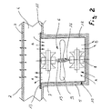
- Such an apparatus comprises a worktop constituted by a board 2 provided with a plurality of through-perforations 3 distributed over the surface thereof, and a chamber 4 communicating with said through-perforations 3; the chamber 4 is obtained by means of an appropriately shaped plate 11 that is associated to the board 2 in correspondence of the lower surface of the latter.
- the chamber 4 is provided with a ventilation conduit 5 which, as connected to said plate 11 or integrally provided therein, constitutes a seat or housing to accommodate fluid-dynamic means, generally indicated at 6, that are adapted to generate a positive pressure or a negative pressure inside said conduit 5 and the chamber 4.
- a ventilation conduit 5 which, as connected to said plate 11 or integrally provided therein, constitutes a seat or housing to accommodate fluid-dynamic means, generally indicated at 6, that are adapted to generate a positive pressure or a negative pressure inside said conduit 5 and the chamber 4.
- These fluid-dynamic means 6 are constituted by a first motor 7, a second motor 8, which is separate and distinct from said first motor 7, and a single fan 9 that is adapted to be driven selectively by said first motor 7 or said second motor 8.
- the first motor 7 and the second motor 8 are adapted to rotate in an opposite direction with respect to each other; they are housed inside the conduit 5 along a same vertical axis and on opposite sides with respect to the fan 9, which therefore turns out to be arranged centrally and coaxially with respect to said first and said second motor 7 and 8, the respective drive shafts 15 and 16 of which are oriented towards the fan 9.
- the latter is in turn coupled with both said drive shafts 15, 16 so that, if the first motor 7 is for instance operated, the second motor 8 will be idling, and vice-versa.
- These means may for instance include a user-actuatable slider that causes the fan 9 to displace, i.e. translate vertically so as to be selectively coupled to a selected one of the two drive shafts 15 or 16, while disengaging it from the other one.
- the selective operation of the motors 7 and 8 is obtained through any suitable means of a per se known type, such as for instance a foot-pedal control provided on the floor and adapted to act on either one of a pair of switches according to the desired direction of rotation.
- the whole assembly formed by the first motor 7, the second motor 8 and the fan 9 is contained within a structure 10 that supports such assembly and secures it to the plate 11; in an advantageous manner, said support and securing structure 10 is constituted by a first bracket 12 to which a second bracket 13 is connected, the second motor 8 and the first motor 7 being associated to these brackets, respectively.
- said structure 10 is connected to the plate 11 in correspondence of the second bracket 13.
- the conduit 5 is advantageously closed at its bottom by means of a protective covering made of a grid-like or perforated material.
- the fan 9, as driven by means of either the first motor 7 or the second motor 8, generates an air flow whose direction depends on the direction of rotation of the driving motor selected; so, for instance, the first motor 7 would cause the fan 9 to rotate in such a direction as to bring about an air flow which, as generally indicated at A, enters the conduit 5 and, therefore, moves from the bottom of the conduit 5 towards the perforations 3; accordingly, the air being sucked, i.e. taken in by the fan 9 will generate a positive pressure inside the chamber 4, thereby causing the air flow A to exit through the perforations 3 and, therefore, the fabric of the garment being to be ironed to be appropriately swelled up and spread out.
- the fan 9 will be caused to rotate in the opposite direction with respect to the one imposed in the above considered case. Accordingly, an air flow will be generated which, as indicated at B, moves out of the conduit 5 and is therefore oriented from the perforations 3 towards the bottom of the conduit 5.
- the air being so exhausted by the fan 9, in this case possibly mixed with steam taken in from the ironing top, will therefore bring about a negative pressure inside the chamber 4, thereby giving rise to a suck-in effect that draws in both air and steam from the ironing top through the perforations 3 and, accordingly, improves the adherence of the fabric onto the ironing top.
- first motor 7 may be arranged to generate a negative pressure
- second motor 8 may on the contrary be arranged to generate a positive pressure
- a further quite important advantage derives from an improved operating efficiency of the fluid-dynamic means: in fact, the presence of a single fan 9 that is capable of rotating in both directions, thereby acting as a pressure fan or as a suction fan according to the direction of rotation, does not imply any fluid-dynamic interference with other adjacent fans.
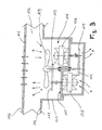
- Figure 3 can be noticed to illustrate a second embodiment of the present invention which, as generally indicated at 101, is shown to comprise a worktop constituted by a board 102 provided with a plurality of through-perforations 103 distributed over the surface thereof, and a chamber 104 which communicates with said through-perforations 103 and is obtained by means of an appropriately shaped plate 11 associated to the board 102.
- the chamber 104 is provided with a ventilation conduit 105 which constitutes a seat or housing to accommodate the fluid-dynamic means that are generally indicated at 106 and are adapted to generate a positive pressure or a negative pressure inside said conduit 105 and the chamber 104.
- These fluid-dynamic means 106 are constituted by a first motor 107, a second motor 108, which is separate and distinct from said first motor 107 and rotates in the opposite direction with respect to the latter, and a single fan 109 that is adapted to be driven selectively by said first motor 107 or said second motor 108 via driving means that may for instance be constituted by a gear train 112, 113, 114, 115.
- the first motor 107, the second motor 108 and the fan 109 are housed inside the conduit 105 along mutually parallel vertical axes by means of a support and securing structure 110 to which said first and said second motor 107, 108 are secured, and to which the fan 109 is connected rotatably.
- the conduit 105 is advantageously closed at its bottom by means of a protective covering made of a grid-like or perforated material.
Landscapes
- Engineering & Computer Science (AREA)
- Textile Engineering (AREA)
- Irons (AREA)
- Treatment Of Fiber Materials (AREA)
- Drying Of Solid Materials (AREA)
- Beans For Foods Or Fodder (AREA)
Claims (8)
- Dampfbügelvorrichtung (1), die umfasst:dadurch gekennzeichnet, dass die Fluiddynamikeinrichtungen (6) durch einen ersten Motor (7) und einen zweiten Motor (8), die so eingerichtet sind, dass sie sich in jeweils entgegengesetzte Richtungen drehen, sowie durch ein einzelnes Gebläse (9) gebildet werden, das so eingerichtet ist, dass es wahlweise von dem ersten Motor (7) angetrieben wird, um den Überdruck zu erzeugen, sowie durch den zweiten Motor (8), um den Unterdruck zu erzeugen, wobei der erste Motor (7) von dem zweiten Motor (8) separat und getrennt ist.eine Arbeitsfläche, die durch ein Brett (2) gebildet wird, das mit einer Vielzahl von Durchgangsöffnungen (3) versehen ist, die über seine Oberfläche verteilt sind;eine Kammer (4), die mit den Durchgangsöffnungen (3) in Verbindung steht und mit dem Brett (2) an einer Position darunter verbunden ist;Fluiddynamikeinrichtungen (6), die so eingerichtet sind, dass sie einen Überdruck und einen Unterdruck in der Kammer (4) erzeugen;eine Aufnahme bzw. ein Gehäuse (5) zur Aufnahme der Fluiddynamikeinrichtungen (6), die/das mit der Kammer (4) in Verbindung steht,
- Dampfbügelvorrichtung (1) nach Anspruch 1, dadurch gekennzeichnet, dass die Kammer (4) mit einer Belüftungsleitung (5) versehen ist, die die Aufnahme bzw. das Gehäuse (5) zum Aufnehmen der Fluiddynamikeinrichtungen (6) bildet.
- Dampfbügelvorrichtung (1) nach Anspruch 1, dadurch gekennzeichnet, dass der erste und der zweite Motor (7, 8) in der Leitung (5) entlang ein und derselben vertikalen Achse an einander gegenüberliegenden Seiten in Bezug auf das Gebläse (9) aufgenommen sind.
- Dampfbügelvorrichtung (1) nach Anspruch 3, dadurch gekennzeichnet, dass das Gebläse (9) mittig zwischen dem ersten und dem zweiten Motor (7, 8) und koaxial dazu angeordnet ist und die entsprechenden Antriebswellen (15, 16) des ersten und des zweiten Motors (7, 8) auf das Gebläse (9) zu gerichtet sind.
- Dampfbügelvorrichtung (1) nach einem oder mehreren der vorangehenden Ansprüche, dadurch gekennzeichnet, dass die Kammer (4) mittels einer geeignet geformten Platte gebildet wird, die mit dem Brett (2) an der unteren Fläche des Brettes (2) verbunden ist.
- Dampfbügelvorrichtung (1) nach Anspruch 5, dadurch gekennzeichnet, dass die Belüftungsleitung (5) mit der Platte (2) verbunden oder integral darin vorhanden ist.
- Dampfbügelvorrichtung (1) nach Anspruch 6, dadurch gekennzeichnet, dass die Fluiddynamikeinrichtungen (6) in einer Struktur (10) enthalten sind, die sowohl die Fluiddynamikeinrichtungen (6) trägt als auch sie an der Platte (2) befestigt.
- Dampfbügelvorrichtung (1) nach einem oder mehreren der vorangehenden Ansprüche, dadurch gekennzeichnet, dass der erste Motor (7), der zweite Motor (8) und das Gehäuse (9) im Inneren der Leitung (5) entlang parallel zueinander verlaufender vertikaler Achsen aufgenommen sind, wobei das Gebläse (9) so eingerichtet ist, dass es über Antriebs-, d.h. Bewegungsübertragungseinrichtungen selektiv von dem ersten Motor (7) oder dem zweiten Motor (8) angetrieben wird.
Applications Claiming Priority (2)
| Application Number | Priority Date | Filing Date | Title |
|---|---|---|---|
| ITPN20010027U | 2001-07-19 | ||
| IT2001PN000027U ITPN20010027U1 (it) | 2001-07-19 | 2001-07-19 | Apparato per la stiratura a vapore |
Publications (2)
| Publication Number | Publication Date |
|---|---|
| EP1277873A1 EP1277873A1 (de) | 2003-01-22 |
| EP1277873B1 true EP1277873B1 (de) | 2004-09-22 |
Family
ID=11453254
Family Applications (1)
| Application Number | Title | Priority Date | Filing Date |
|---|---|---|---|
| EP02014511A Expired - Lifetime EP1277873B1 (de) | 2001-07-19 | 2002-07-01 | Dampfbügelvorrichtung |
Country Status (5)
| Country | Link |
|---|---|
| EP (1) | EP1277873B1 (de) |
| AT (1) | ATE277221T1 (de) |
| DE (1) | DE60201304T2 (de) |
| ES (1) | ES2229022T3 (de) |
| IT (1) | ITPN20010027U1 (de) |
Families Citing this family (5)
| Publication number | Priority date | Publication date | Assignee | Title |
|---|---|---|---|---|
| EP1705284A1 (de) | 2005-03-22 | 2006-09-27 | Hailo-Werk Rudolf Loh GmbH & Co. KG | Dampfbügeltisch mit Mittel zum Erzeugen einer Luftströmung |
| WO2007121758A1 (de) * | 2006-04-18 | 2007-11-01 | Veit Gmbh | Bügeltisch |
| ES2401867T3 (es) * | 2010-11-11 | 2013-04-25 | Miele & Cie. Kg | Equipo para planchar |
| CN103614895A (zh) * | 2013-12-13 | 2014-03-05 | 安徽浙苏服装水洗有限公司 | 衣物熨烫台 |
| CN107916552A (zh) * | 2017-12-28 | 2018-04-17 | 宁波雯泽纺织品有限公司 | 棉织品烘干装置 |
Family Cites Families (3)
| Publication number | Priority date | Publication date | Assignee | Title |
|---|---|---|---|---|
| CH690443A5 (fr) * | 1995-06-19 | 2000-09-15 | Divelit S A | Installation de repassage domestique. |
| DE19629896A1 (de) * | 1996-07-24 | 1998-04-30 | Veit Gmbh & Co | Bügeltisch mit Saug-Blas-Vorrichtung |
| IT246328Y1 (it) * | 1998-07-31 | 2002-04-08 | Esse 85 Srl | Impianto di stiratura a vapore |
-
2001
- 2001-07-19 IT IT2001PN000027U patent/ITPN20010027U1/it unknown
-
2002
- 2002-07-01 EP EP02014511A patent/EP1277873B1/de not_active Expired - Lifetime
- 2002-07-01 ES ES02014511T patent/ES2229022T3/es not_active Expired - Lifetime
- 2002-07-01 DE DE60201304T patent/DE60201304T2/de not_active Expired - Fee Related
- 2002-07-01 AT AT02014511T patent/ATE277221T1/de not_active IP Right Cessation
Also Published As
| Publication number | Publication date |
|---|---|
| ATE277221T1 (de) | 2004-10-15 |
| DE60201304D1 (de) | 2004-10-28 |
| DE60201304T2 (de) | 2005-11-17 |
| ITPN20010027V0 (it) | 2001-07-19 |
| ITPN20010027U1 (it) | 2003-01-19 |
| EP1277873A1 (de) | 2003-01-22 |
| ES2229022T3 (es) | 2005-04-16 |
Similar Documents
| Publication | Publication Date | Title |
|---|---|---|
| EP3020319B1 (de) | Haushaltsgeschirrspülmaschine | |
| US9534843B2 (en) | Laundry treating machine with basement portion providing airflow paths | |
| GB2248289A (en) | Tumble dryer and versatile heater/ventilator | |
| EP1277873B1 (de) | Dampfbügelvorrichtung | |
| US2362590A (en) | Flatiron | |
| EP2009172A2 (de) | Elektrisches Dampfbügeleisen | |
| KR101362786B1 (ko) | 건조기 | |
| EP2290143A1 (de) | Wäschebehandlungssystem | |
| JPH09103600A (ja) | 家庭用アイロン装置 | |
| AU2016296421B2 (en) | Ironing board with steam-releasing board for domestic use with various ironing modes | |
| EP1362137B1 (de) | Bügeltisch mit saugvorrichtung und/oder blasvorrichtung | |
| JP3920128B2 (ja) | 洗濯乾燥機 | |
| EP1338694B1 (de) | Dampfbügelvorrichtung | |
| JP3920303B1 (ja) | 洗濯乾燥機 | |
| EP1379723A2 (de) | Bügeleisen | |
| KR101007474B1 (ko) | 차량 및 가정용 스팀 복합기 | |
| CN101851840A (zh) | 洗涤干燥机 | |
| KR100484391B1 (ko) | 다림질판 | |
| USRE49173E1 (en) | Fabric treating apparatus | |
| EP0976864B1 (de) | Dampfbügelvorrichtung | |
| EP3674474B1 (de) | Wäschebehandlungsvorrichtung | |
| RU2008104633A (ru) | Способ управления активной гладильной доской | |
| KR20220156316A (ko) | 레인지 후드 및 이를 포함하는 조리 기기 | |
| US3374563A (en) | Electric iron | |
| JP2019000256A (ja) | 洗濯機および洗濯乾燥機 |
Legal Events
| Date | Code | Title | Description |
|---|---|---|---|
| PUAI | Public reference made under article 153(3) epc to a published international application that has entered the european phase |
Free format text: ORIGINAL CODE: 0009012 |
|
| AK | Designated contracting states |
Kind code of ref document: A1 Designated state(s): AT BE BG CH CY CZ DE DK EE ES FI FR GB GR IE IT LI LU MC NL PT SE SK TR |
|
| AX | Request for extension of the european patent |
Free format text: AL;LT;LV;MK;RO;SI |
|
| 17P | Request for examination filed |
Effective date: 20030621 |
|
| AKX | Designation fees paid |
Designated state(s): AT BE BG CH CY CZ DE DK EE ES FI FR GB GR IE IT LI LU MC NL PT SE SK TR |
|
| GRAP | Despatch of communication of intention to grant a patent |
Free format text: ORIGINAL CODE: EPIDOSNIGR1 |
|
| GRAS | Grant fee paid |
Free format text: ORIGINAL CODE: EPIDOSNIGR3 |
|
| GRAA | (expected) grant |
Free format text: ORIGINAL CODE: 0009210 |
|
| AK | Designated contracting states |
Kind code of ref document: B1 Designated state(s): AT BE BG CH CY CZ DE DK EE ES FI FR GB GR IE IT LI LU MC NL PT SE SK TR |
|
| PG25 | Lapsed in a contracting state [announced via postgrant information from national office to epo] |
Ref country code: TR Free format text: LAPSE BECAUSE OF FAILURE TO SUBMIT A TRANSLATION OF THE DESCRIPTION OR TO PAY THE FEE WITHIN THE PRESCRIBED TIME-LIMIT Effective date: 20040922 Ref country code: SK Free format text: LAPSE BECAUSE OF FAILURE TO SUBMIT A TRANSLATION OF THE DESCRIPTION OR TO PAY THE FEE WITHIN THE PRESCRIBED TIME-LIMIT Effective date: 20040922 Ref country code: NL Free format text: LAPSE BECAUSE OF FAILURE TO SUBMIT A TRANSLATION OF THE DESCRIPTION OR TO PAY THE FEE WITHIN THE PRESCRIBED TIME-LIMIT Effective date: 20040922 Ref country code: LI Free format text: LAPSE BECAUSE OF FAILURE TO SUBMIT A TRANSLATION OF THE DESCRIPTION OR TO PAY THE FEE WITHIN THE PRESCRIBED TIME-LIMIT Effective date: 20040922 Ref country code: FI Free format text: LAPSE BECAUSE OF FAILURE TO SUBMIT A TRANSLATION OF THE DESCRIPTION OR TO PAY THE FEE WITHIN THE PRESCRIBED TIME-LIMIT Effective date: 20040922 Ref country code: EE Free format text: LAPSE BECAUSE OF FAILURE TO SUBMIT A TRANSLATION OF THE DESCRIPTION OR TO PAY THE FEE WITHIN THE PRESCRIBED TIME-LIMIT Effective date: 20040922 Ref country code: CZ Free format text: LAPSE BECAUSE OF FAILURE TO SUBMIT A TRANSLATION OF THE DESCRIPTION OR TO PAY THE FEE WITHIN THE PRESCRIBED TIME-LIMIT Effective date: 20040922 Ref country code: CH Free format text: LAPSE BECAUSE OF FAILURE TO SUBMIT A TRANSLATION OF THE DESCRIPTION OR TO PAY THE FEE WITHIN THE PRESCRIBED TIME-LIMIT Effective date: 20040922 Ref country code: BG Free format text: LAPSE BECAUSE OF FAILURE TO SUBMIT A TRANSLATION OF THE DESCRIPTION OR TO PAY THE FEE WITHIN THE PRESCRIBED TIME-LIMIT Effective date: 20040922 Ref country code: BE Free format text: LAPSE BECAUSE OF FAILURE TO SUBMIT A TRANSLATION OF THE DESCRIPTION OR TO PAY THE FEE WITHIN THE PRESCRIBED TIME-LIMIT Effective date: 20040922 Ref country code: AT Free format text: LAPSE BECAUSE OF FAILURE TO SUBMIT A TRANSLATION OF THE DESCRIPTION OR TO PAY THE FEE WITHIN THE PRESCRIBED TIME-LIMIT Effective date: 20040922 |
|
| REG | Reference to a national code |
Ref country code: GB Ref legal event code: FG4D |
|
| REG | Reference to a national code |
Ref country code: CH Ref legal event code: EP |
|
| REG | Reference to a national code |
Ref country code: IE Ref legal event code: FG4D |
|
| REF | Corresponds to: |
Ref document number: 60201304 Country of ref document: DE Date of ref document: 20041028 Kind code of ref document: P |
|
| PG25 | Lapsed in a contracting state [announced via postgrant information from national office to epo] |
Ref country code: SE Free format text: LAPSE BECAUSE OF FAILURE TO SUBMIT A TRANSLATION OF THE DESCRIPTION OR TO PAY THE FEE WITHIN THE PRESCRIBED TIME-LIMIT Effective date: 20041222 Ref country code: GR Free format text: LAPSE BECAUSE OF FAILURE TO SUBMIT A TRANSLATION OF THE DESCRIPTION OR TO PAY THE FEE WITHIN THE PRESCRIBED TIME-LIMIT Effective date: 20041222 Ref country code: DK Free format text: LAPSE BECAUSE OF FAILURE TO SUBMIT A TRANSLATION OF THE DESCRIPTION OR TO PAY THE FEE WITHIN THE PRESCRIBED TIME-LIMIT Effective date: 20041222 |
|
| REG | Reference to a national code |
Ref country code: CH Ref legal event code: PL |
|
| NLV1 | Nl: lapsed or annulled due to failure to fulfill the requirements of art. 29p and 29m of the patents act | ||
| REG | Reference to a national code |
Ref country code: ES Ref legal event code: FG2A Ref document number: 2229022 Country of ref document: ES Kind code of ref document: T3 |
|
| PG25 | Lapsed in a contracting state [announced via postgrant information from national office to epo] |
Ref country code: IT Free format text: LAPSE BECAUSE OF NON-PAYMENT OF DUE FEES Effective date: 20050701 Ref country code: IE Free format text: LAPSE BECAUSE OF NON-PAYMENT OF DUE FEES Effective date: 20050701 Ref country code: CY Free format text: LAPSE BECAUSE OF FAILURE TO SUBMIT A TRANSLATION OF THE DESCRIPTION OR TO PAY THE FEE WITHIN THE PRESCRIBED TIME-LIMIT Effective date: 20050701 |
|
| PG25 | Lapsed in a contracting state [announced via postgrant information from national office to epo] |
Ref country code: ES Free format text: LAPSE BECAUSE OF NON-PAYMENT OF DUE FEES Effective date: 20050702 |
|
| ET | Fr: translation filed | ||
| PLBE | No opposition filed within time limit |
Free format text: ORIGINAL CODE: 0009261 |
|
| STAA | Information on the status of an ep patent application or granted ep patent |
Free format text: STATUS: NO OPPOSITION FILED WITHIN TIME LIMIT |
|
| PG25 | Lapsed in a contracting state [announced via postgrant information from national office to epo] |
Ref country code: MC Free format text: LAPSE BECAUSE OF NON-PAYMENT OF DUE FEES Effective date: 20050731 |
|
| 26N | No opposition filed |
Effective date: 20050623 |
|
| PG25 | Lapsed in a contracting state [announced via postgrant information from national office to epo] |
Ref country code: DE Free format text: LAPSE BECAUSE OF NON-PAYMENT OF DUE FEES Effective date: 20060201 |
|
| PG25 | Lapsed in a contracting state [announced via postgrant information from national office to epo] |
Ref country code: FR Free format text: LAPSE BECAUSE OF NON-PAYMENT OF DUE FEES Effective date: 20060331 |
|
| REG | Reference to a national code |
Ref country code: IE Ref legal event code: MM4A |
|
| REG | Reference to a national code |
Ref country code: FR Ref legal event code: ST Effective date: 20060331 |
|
| PG25 | Lapsed in a contracting state [announced via postgrant information from national office to epo] |
Ref country code: GB Free format text: LAPSE BECAUSE OF NON-PAYMENT OF DUE FEES Effective date: 20060701 |
|
| REG | Reference to a national code |
Ref country code: ES Ref legal event code: FD2A Effective date: 20050702 |
|
| GBPC | Gb: european patent ceased through non-payment of renewal fee |
Effective date: 20060701 |
|
| PG25 | Lapsed in a contracting state [announced via postgrant information from national office to epo] |
Ref country code: PT Free format text: LAPSE BECAUSE OF NON-PAYMENT OF DUE FEES Effective date: 20050222 |