EP1277924A2 - Support pour la désactivation assistée mécaniquement et un culbuteur à deux-pas - Google Patents
Support pour la désactivation assistée mécaniquement et un culbuteur à deux-pas Download PDFInfo
- Publication number
- EP1277924A2 EP1277924A2 EP02077349A EP02077349A EP1277924A2 EP 1277924 A2 EP1277924 A2 EP 1277924A2 EP 02077349 A EP02077349 A EP 02077349A EP 02077349 A EP02077349 A EP 02077349A EP 1277924 A2 EP1277924 A2 EP 1277924A2
- Authority
- EP
- European Patent Office
- Prior art keywords
- finger follower
- roller finger
- face
- mechanical assist
- arm
- Prior art date
- Legal status (The legal status is an assumption and is not a legal conclusion. Google has not performed a legal analysis and makes no representation as to the accuracy of the status listed.)
- Withdrawn
Links
Images


Classifications
-
- F—MECHANICAL ENGINEERING; LIGHTING; HEATING; WEAPONS; BLASTING
- F01—MACHINES OR ENGINES IN GENERAL; ENGINE PLANTS IN GENERAL; STEAM ENGINES
- F01L—CYCLICALLY OPERATING VALVES FOR MACHINES OR ENGINES
- F01L1/00—Valve-gear or valve arrangements, e.g. lift-valve gear
- F01L1/12—Transmitting gear between valve drive and valve
- F01L1/18—Rocking arms or levers
- F01L1/181—Centre pivot rocking arms
- F01L1/182—Centre pivot rocking arms the rocking arm being pivoted about an individual fulcrum, i.e. not about a common shaft
-
- F—MECHANICAL ENGINEERING; LIGHTING; HEATING; WEAPONS; BLASTING
- F01—MACHINES OR ENGINES IN GENERAL; ENGINE PLANTS IN GENERAL; STEAM ENGINES
- F01L—CYCLICALLY OPERATING VALVES FOR MACHINES OR ENGINES
- F01L1/00—Valve-gear or valve arrangements, e.g. lift-valve gear
- F01L1/12—Transmitting gear between valve drive and valve
- F01L1/18—Rocking arms or levers
- F01L1/185—Overhead end-pivot rocking arms
-
- F—MECHANICAL ENGINEERING; LIGHTING; HEATING; WEAPONS; BLASTING
- F01—MACHINES OR ENGINES IN GENERAL; ENGINE PLANTS IN GENERAL; STEAM ENGINES
- F01L—CYCLICALLY OPERATING VALVES FOR MACHINES OR ENGINES
- F01L13/00—Modifications of valve-gear to facilitate reversing, braking, starting, changing compression ratio, or other specific operations
- F01L13/0005—Deactivating valves
-
- F—MECHANICAL ENGINEERING; LIGHTING; HEATING; WEAPONS; BLASTING
- F01—MACHINES OR ENGINES IN GENERAL; ENGINE PLANTS IN GENERAL; STEAM ENGINES
- F01L—CYCLICALLY OPERATING VALVES FOR MACHINES OR ENGINES
- F01L1/00—Valve-gear or valve arrangements, e.g. lift-valve gear
- F01L1/12—Transmitting gear between valve drive and valve
- F01L1/18—Rocking arms or levers
- F01L2001/186—Split rocking arms, e.g. rocker arms having two articulated parts and means for varying the relative position of these parts or for selectively connecting the parts to move in unison
-
- F—MECHANICAL ENGINEERING; LIGHTING; HEATING; WEAPONS; BLASTING
- F01—MACHINES OR ENGINES IN GENERAL; ENGINE PLANTS IN GENERAL; STEAM ENGINES
- F01L—CYCLICALLY OPERATING VALVES FOR MACHINES OR ENGINES
- F01L2305/00—Valve arrangements comprising rollers
- F01L2305/02—Mounting of rollers
-
- F—MECHANICAL ENGINEERING; LIGHTING; HEATING; WEAPONS; BLASTING
- F01—MACHINES OR ENGINES IN GENERAL; ENGINE PLANTS IN GENERAL; STEAM ENGINES
- F01L—CYCLICALLY OPERATING VALVES FOR MACHINES OR ENGINES
- F01L2820/00—Details on specific features characterising valve gear arrangements
- F01L2820/03—Auxiliary actuators
- F01L2820/031—Electromagnets
Definitions
- the present invention generally relates to actuation mechanisms for use with deactivation and two-step roller finger followers (RFFs).
- Deactivation RFFs typically include a body and a roller carried by a shaft.
- the roller is engaged by a cam of an engine camshaft that causes the RFF body to pivot, thereby actuating an associated engine valve.
- the deactivation RFF is selectively switched between a coupled and a decoupled mode of operation.
- the shaft In the coupled mode the shaft is coupled to the body, and rotation of the output cam is transferred from the roller through the shaft to pivotal movement of the RFF body, which, in turn, reciprocates the associated valve.
- the shaft In the decoupled mode, the shaft is decoupled from the body.
- the shaft does not transfer rotation of the output cam to pivotal movement of the RFF body and the associated valve is deactivated, i.e., not lifted or reciprocated, and therefore the term deactivation is used to describe this type of RFF.
- Zero-lift lobes on either side of the main cam engage and maintain the RFF body in a fixed position while in the decoupled mode of operation.
- a two-step RFF operates in a manner similar to a deactivation RFF, as described above. However, rather than the body being engaged by zero-lift cam lobes as in the case of a deactivation RFF, the body of the two-step RFF is engaged by low-lift cam lobes. In the decoupled mode, the body of the two-step RFF is pivoted by the low-lift lobes thereby actuating the associated engine valve according to the lift profile of the low-lift cam lobes. In the coupled mode, the body of the two-step RFF is pivoted by the main cam thereby actuating the associated engine valve according to the lift profile of the main cam. Thus, the two-step RFF activates the associated valve according to a selected one of two different lift profiles, and therefore the term two step is used to describe this type of RFF.
- RFF encompasses both a deactivation RFF and a two-step RFF. Both types of RFFs are selectively switched between the coupled and decoupled modes of operation through the use of a locking pin assembly that couples and decouples the shaft to and from the RFF body.
- the locking pin assembly is a two-part pin that is biased by an associated spring into a default position, such as, for example, the decoupled position wherein the shaft is decoupled from the RFF body.
- an actuating device is associated with the locking pin assembly.
- the actuating mechanism engages a trigger pin of the locking pin assembly to place and maintain the RFF in a first mode, such as, for example, the coupled mode.
- the actuating mechanism disengages from the trigger pin to thereby enable an internal spring of the locking pin assembly to bias the assembly into the second mode, such as, for example, the default/decoupled mode.
- the actuating mechanism such as, for example, a direct acting electromechanical solenoid or hydraulic actuator, engages the locking pin assembly to thereby place the locking pin assembly in one of the coupled and decoupled positions, such as, for example, the coupled position.
- an actuating mechanism In order to engage the locking pin assembly, an actuating mechanism must be disposed adjacent to the locking pin assembly of each RFF, and within the limited space available in the head of modern engines. Further, the actuating mechanism must provide sufficient force and stroke length in order to translate the locking pin mechanism, and thereby switch the mode of the RFF.
- Such direct acting mechanism require relatively large amounts of input power to initiate motion at relatively long distances. Moreover, the actuating mechanism must be precisely aligned with the locking pin assembly of the RFF in order to ensure smooth switching between modes.
- the present invention provides a mechanical assist actuation bracket for use with a deactivation and/or two-step roller finger follower.
- the roller finger follower includes a locking pin assembly having a trigger pin.
- the invention comprises, in one form thereof, a mechanical assist actuation bracket configured for being affixed to the roller finger follower.
- the bracket includes a face and an arm extending from the face.
- the arm is configured for translating an actuating arm of an actuating device associated with the roller finger follower in a direction toward and away from the trigger pin during pivotal movement of the roller finger follower.
- An advantage of the present invention is that the bracket, by translating the actuating arm of the actuating device, reduces the power requirements of the actuating device thereby enabling the use of an actuating device having a reduced power rating and a smaller size.
- Another advantage of the present invention is that the bracket reduces the distances over which the actuating mechanism associated with the RFF must act, and thereby reduces the amount of electrical drive current required by the actuating mechanism.
- bracket increases the alignment tolerance between the actuating mechanism and the trigger pin of the locking pin assembly.
- a still further advantage of the present invention is that mode switching of the roller finger follower occurs during the base circle phase of the cam event, and thus the switching event is self-timed.
- An even further advantage of the present invention is that the mode switching event of the roller finger can utilize the entire base circle phase of the cam event, thus allowing substantial time for the switching event to occur.
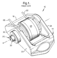
- roller finger follower 10 is installed in internal combustion engine 12.
- RFF 10 includes body 14 having a first end 16 that, in use, engages a valve stem of an associated valve (neither of which are shown) of engine 12, and a second end (not referenced) engages a stem of a lash adjuster (neither of which are shown) of engine 12.
- RFF 10 is configured as, for example, a deactivation RFF.
- the mechanical assist actuation bracket of the present invention can be configured for use with either a deactivation RFF or a two-step RFF.
- RFF 10 further includes locking pin assembly 20, sides 22 and 24, roller 26, lost motion springs 28 and shaft 30.
- Roller 26 is engaged by a cam of a camshaft (neither of which are shown) of engine 12.
- Locking pin assembly 20 has central axis A, and is disposed within hollow shaft 30, which is also substantially concentric relative to central axis A.
- locking pin 20 engages orifices (not shown) in a respective inside surface of each of sides 22 and 24 to thereby couple shaft 30 and roller 26 to RFF body 14.
- RFF 10 With RFF 10 in the coupled mode, rotary motion of the cam is transferred by roller 26 and shaft 30 to pivoting of RFF body 14 to thereby reciprocate the valve stem and actuate the associated valve.
- Locking pin assembly 20 includes trigger pin 32. Trigger pin 32 is biased by an internal spring (not shown) of locking pin assembly 20 to thereby position locking pin assembly 20 in, for example, the coupled mode.
- Trigger pin 32 is engaged by an actuating member, and is thereby translated axially inward, i.e., in the direction toward side 24 to thereby place RFF 10 in, for example, the decoupled mode.
- the pin members of locking pin assembly 20 align such that shaft 30 and roller 26 are decoupled from RFF body 14.
- Valve stem 18 is not pivoted, and the associated valve is not actuated by the motion of the cam while RFF 10 is in the decoupled mode.
- RFF 10 in the decoupled mode and configured as a two-step RFF, the valve would be actuated according to low-lift cam lobes disposed on either side of the cam that engages roller 26.
- lost motion springs 28 absorb the motion of roller 26 and maintain roller 26 in contact with the cam.
- RFF 40 is generally similar to and has many parts in common with RFF 10, and corresponding reference characters indicate corresponding parts common to RFF 10 and RFF 40.
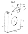
- RFF 40 includes mechanical assist actuation bracket 44, which is attached, such as, for example, by a snap or crimp fit or other suitable means, to side 22 of RFF body 12.
- bracket 44 includes sides 52 that are interconnected and spaced apart by face 54.
- Face 54 includes central orifice 56, through which trigger pin 32 extends (as shown in Fig. 2).
- Central orifice 56 is dimensioned such that it does not interfere with the displacement of trigger pin 32 in a direction toward and away from side 22 required to switch RFF 10 between the decoupled and coupled modes of operation.
- Bracket 44 further includes an elongate, generally L-shaped angled arm 58.
- Arm 58 includes first portion 58a and second portion 58b.
- First portion 58a extends from face 54 in a direction away from side 22 and at an angle of from approximately twenty degrees to approximately seventy-five degrees relative to the plane of face 54.
- Second portion 58b of arm 58 is angled such that it is substantially parallel relative to the plane of face 54.
- L-shaped arm 58 and bracket 44 are constructed of, for example, spring steel.
- an actuating device such as, for example, an electric or hydraulic solenoid, is associated with each RFF 40 in order to actuate trigger pin 32 and thereby switch RFF 40 between the decoupled and coupled modes of operation.
- bracket 44 reduces the distance through and the force with which the actuating device must act to translate pin assembly 20.
- the drive current required in order to activate the actuating device is reduced, thereby enabling the use of a smaller actuating device to activate RFF 40 and the electrical current required in order to energize the actuator is reduced.
- bracket 44, and thus RFF 40 increases the positioning tolerance of the actuating device relative to RFF 40.
- RFF 40 is operably disposed in association with actuating device 60, such as, for example, a hydraulic or electric solenoid.
- Actuating device 60 generally includes body 62, spring 64 and actuating arm 66.
- Spring 64 engages each of body 62 and end 66a of actuating arm 66, thereby biasing actuating arm 66 into a fully extended position (Fig. 4A).
- Actuating device 60 is disposed adjacent RFF 40, with centerline C of actuating arm 66 generally concentric with central axis A of locking pin assembly 20.
- Fig. 4A depicts RFF 40, or more particularly roller 26 thereof, on the base circle of the cam of the camshaft of engine 12.
- Actuating arm 66 is fully extended by spring 64 into engagement with trigger pin 32 of locking pin assembly 20.
- the force exerted by spring 64 upon actuating arm 66 in a direction toward RFF 40 is of sufficient magnitude to translate trigger pin 32 in the direction of side 24 of RFF body 14, and thereby dispose locking pin assembly 20 in the coupled position.
- End 66a of actuating arm 66 is in engagement with trigger pin 32 of locking pin assembly 20 and with face 54 of bracket 44.
- End 66a is dimensioned such that it is somewhat larger than orifice 56 of bracket 44, and thus does not extend into or through orifice 56.
- actuating arm 66 translates trigger pin 32 axially such that locking pin assembly 20 is placed into the coupled position to thereby place RFF 40 in the coupled mode of operation.
- RFF 40 is depicted during a valve opening event, i.e., roller 26 is engaged by the lift profile or nose of the cam of the camshaft of engine 12.
- RFF body 12 is pivoted about the lash adjuster (not shown) such that first end 16 of RFF body 12 is pivoted downward, i.e., toward the associated valve, such that central axis A is somewhat lower than centerline C of actuating arm 66.
- RFF body 12 carries bracket 44, and thus bracket 44 and arm 58 thereof are displaced in the same direction as RFF body 12.
- first, angled portion 58a of arm 58 progressively engages end 66a of actuating arm 66.
- arm 58 moves downward relative to end 66a such that end 66a is progressively engaged by angled portion 58a, thereby displacing actuating arm 66 in a direction axially toward, or inward, relative to body 62 and away from trigger pin 32 until arm 66 is in the fully seated position.
- the inward displacement of arm 58 compresses spring 64.
- Arm 58 is constructed of, for example, spring steel, such that it can deflect after actuating arm 66is fully seated, thus allowing the axial location of actuator 62 to vary relative to RFF 40.
- the decoupled mode is selected by energizing actuating device 60 some time prior to a valve-opening event.
- actuating device 60 is energized some time prior to the situation when arm 58, actuating arm 66 and RFF body 12 are in the relative positions depicted in Fig. 4B.
- arm 58 pushes actuating arm 66 axially toward actuating device 60 and away from trigger pin 32.
- Energizing actuating device 60 simply maintains actuating arm 66 in the retracted position, i.e., translated away from RFF body 12 as shown in Fig.
- Actuating device 60 is relatively low powered since retraction of actuating arm 66 to the fully seated position is accomplished by the force applied thereto by arm 58 of bracket 44, and extension is accomplished by the biasing force of spring 64 in the absence of a counteracting force applied by arm 58.
- energizing actuating device 60 maintains actuating arm 66 in the retracted position, i.e., retracted axially away from RFF body 12 and trigger pin 32 of locking pin assembly 20.
- roller 26 and, thus, RFF 40 are not loaded by the valve spring of the valve associated with RFF 40.
- trigger pin 32 translates outward, i.e., in a direction toward actuating device 60.
- Locking pin assembly 20 is then biased into the decoupled position by the internal spring thereof, and RFF 40 is thereby placed into the decoupled mode of operation.
- roller 26 Since roller 26 is decoupled from RFF body 12, the rotation of the cam is not transferred to pivotal motion of RFF body 12, and the corresponding valve is not actuated or is actuated according to the lift profile of low-lift cam lobes associated with RFF 40.
- the mechanism is self timed to allow the translation of locking pin assembly 20 to occur only at the beginning of the base circle phase of the cam profile.
- RFF 40 remains in the decoupled mode of operation until actuating device 60 is de-energized.
- spring 64 biases actuating arm 66 outward, i.e., in a direction toward RFF 40, and into engagement with trigger pin 32.
- end 66a of actuating arm 66 engages and displaces trigger pin 32 in a direction away from actuating device 60, and thereby translates locking pin assembly 20 back into the coupled position.
Landscapes
- Engineering & Computer Science (AREA)
- Mechanical Engineering (AREA)
- General Engineering & Computer Science (AREA)
- Valve-Gear Or Valve Arrangements (AREA)
- Prostheses (AREA)
- Manipulator (AREA)
- Massaging Devices (AREA)
- Valve Device For Special Equipments (AREA)
Applications Claiming Priority (2)
| Application Number | Priority Date | Filing Date | Title |
|---|---|---|---|
| US09/906,277 US6463897B2 (en) | 2000-05-16 | 2001-07-16 | Mechanical assist actuation bracket for deactivation and two-step roller finger followers |
| US906277 | 2001-07-16 |
Publications (2)
| Publication Number | Publication Date |
|---|---|
| EP1277924A2 true EP1277924A2 (fr) | 2003-01-22 |
| EP1277924A3 EP1277924A3 (fr) | 2003-11-05 |
Family
ID=25422187
Family Applications (1)
| Application Number | Title | Priority Date | Filing Date |
|---|---|---|---|
| EP02077349A Withdrawn EP1277924A3 (fr) | 2001-07-16 | 2002-06-14 | Support pour la désactivation assistée mécaniquement et un culbuteur à deux-pas |
Country Status (2)
| Country | Link |
|---|---|
| US (1) | US6463897B2 (fr) |
| EP (1) | EP1277924A3 (fr) |
Cited By (2)
| Publication number | Priority date | Publication date | Assignee | Title |
|---|---|---|---|---|
| EP1388644A1 (fr) * | 2002-08-08 | 2004-02-11 | Eaton Corporation | Désactivation de soupape avec un actionneur électro-hydraulique |
| EP1770248A1 (fr) * | 2005-09-30 | 2007-04-04 | Delphi Technologies, Inc. | Mécanisme de synchronisation pour un culbuteur à galet à 2 positions |
Families Citing this family (16)
| Publication number | Priority date | Publication date | Assignee | Title |
|---|---|---|---|---|
| US6755167B2 (en) | 2002-02-26 | 2004-06-29 | Delphi Technologies, Inc. | Two-step roller finger cam follower having spool-shaped low-lift roller |
| KR100836917B1 (ko) | 2006-09-21 | 2008-06-11 | 현대자동차주식회사 | 가변 밸브 리프트 장치의 캠팔로어 구조 |
| US8006657B2 (en) * | 2006-12-01 | 2011-08-30 | Ford Global Technologies, Llc | Mode-switching cam follower |
| KR100909496B1 (ko) | 2007-09-19 | 2009-07-27 | 고려대학교 산학협력단 | 엔진의 연속 가변 밸브 리프트 장치 |
| FR2979945B1 (fr) * | 2011-09-12 | 2016-05-06 | Valeo Systemes De Controle Moteur | Systeme de transmission du mouvement d'au moins deux cames a au moins une soupape |
| JP5984460B2 (ja) * | 2012-03-30 | 2016-09-06 | 本田技研工業株式会社 | 内燃機関の可変動弁機構 |
| FR2990483B1 (fr) * | 2012-05-14 | 2015-01-09 | Valeo Sys Controle Moteur Sas | Dispositif de verrouillage pour un systeme de transmission du mouvement d'au moins une came a au moins une soupape |
| FR2990484B1 (fr) * | 2012-05-14 | 2015-01-09 | Valeo Sys Controle Moteur Sas | Dispositif de verrouillage pour un systeme de transmission du mouvement d'au moins une came a au moins une soupape |
| FR2990465B1 (fr) * | 2012-05-14 | 2016-01-15 | Valeo Sys Controle Moteur Sas | Ensemble de levee multiple de soupape |
| FR2995935B1 (fr) * | 2012-09-25 | 2015-07-31 | Valeo Sys Controle Moteur Sas | Ensemble de transmission du mouvement d'au moins une came |
| WO2015020678A1 (fr) * | 2013-08-09 | 2015-02-12 | Diggs Matthew B | Ensemble ressorts de soupape à torsion hélicoïdaux |
| JP6700089B2 (ja) * | 2016-04-08 | 2020-05-27 | 株式会社オティックス | ロッカアーム |
| DE102017101792B4 (de) * | 2017-01-31 | 2018-11-15 | Schaeffler Technologies AG & Co. KG | Variabler Ventiltrieb eines Verbrennungskolbenmotors |
| US10900385B2 (en) | 2019-01-29 | 2021-01-26 | Delphi Technologies Ip Limited | Switchable rocker arm |
| US10871087B2 (en) | 2019-01-29 | 2020-12-22 | Delphi Technologies Ip Limited | Switchable rocker arm |
| DE112020002589T5 (de) * | 2019-05-24 | 2022-03-10 | Eaton Intelligent Power Limited | Metallgestanzter schaltrollenfingerfolger |
Family Cites Families (5)
| Publication number | Priority date | Publication date | Assignee | Title |
|---|---|---|---|---|
| DE3119133A1 (de) * | 1981-05-14 | 1982-12-02 | Anton Ing.(grad.) 8492 Furth Pfeifer | "ventilsteuerungseinrichtung fuer viertakt-verbrennungsmotoren" |
| US6092497A (en) * | 1997-10-30 | 2000-07-25 | Eaton Corporation | Electromechanical latching rocker arm valve deactivator |
| US6321705B1 (en) * | 1999-10-15 | 2001-11-27 | Delphi Technologies, Inc. | Roller finger follower for valve deactivation |
| JP3876589B2 (ja) * | 2000-05-11 | 2007-01-31 | いすゞ自動車株式会社 | 気筒制御式エンジンの弁休止機構 |
| US6604498B2 (en) * | 2000-05-16 | 2003-08-12 | Delphi Technologies, Inc. | Actuation mechanism for mode-switching roller finger follower |
-
2001
- 2001-07-16 US US09/906,277 patent/US6463897B2/en not_active Expired - Fee Related
-
2002
- 2002-06-14 EP EP02077349A patent/EP1277924A3/fr not_active Withdrawn
Cited By (3)
| Publication number | Priority date | Publication date | Assignee | Title |
|---|---|---|---|---|
| EP1388644A1 (fr) * | 2002-08-08 | 2004-02-11 | Eaton Corporation | Désactivation de soupape avec un actionneur électro-hydraulique |
| EP1770248A1 (fr) * | 2005-09-30 | 2007-04-04 | Delphi Technologies, Inc. | Mécanisme de synchronisation pour un culbuteur à galet à 2 positions |
| US7278384B2 (en) | 2005-09-30 | 2007-10-09 | Delphi Technologies, Inc. | Timing mechanism for a switchable two-step roller finger follower |
Also Published As
| Publication number | Publication date |
|---|---|
| EP1277924A3 (fr) | 2003-11-05 |
| US6463897B2 (en) | 2002-10-15 |
| US20010045197A1 (en) | 2001-11-29 |
Similar Documents
| Publication | Publication Date | Title |
|---|---|---|
| US6463897B2 (en) | Mechanical assist actuation bracket for deactivation and two-step roller finger followers | |
| EP2839123B1 (fr) | Culbuteur commutable | |
| EP0833041B1 (fr) | Une commande électromagnétique pour activer un culbuteur verrouillable | |
| JP4068176B2 (ja) | 内撚機関のバルブ制御システム | |
| EP3464837B1 (fr) | Appareil d'actionnement | |
| WO2017060496A1 (fr) | Ensemble culbuteur pour un moteur à combustion interne | |
| EP0860588B1 (fr) | Dispositif de commande de soupape permettant la sélection de deux levées différentes | |
| US8186318B2 (en) | Variable valve operating apparatus for internal combustion engine | |
| US11781452B2 (en) | Valve train assembly | |
| JP7526892B2 (ja) | ロストモーションエンジンバルブ作動システム内のロッカー制御 | |
| US6467445B1 (en) | Deactivation and two-step roller finger follower having a slider bracket | |
| EP3891365B1 (fr) | Linguet pour commutation de lobe et mouvement perdu de source unique | |
| US11015492B2 (en) | Lower travel deactivating lash adjuster when combined with two-step variable valve lift rocker arm | |
| US6745733B2 (en) | Actuating system for mode-switching rocker arm device | |
| US11236643B2 (en) | Actuation apparatus | |
| CN117642550A (zh) | 具有主摇杆和分叉辅助摇杆的摇臂组件 | |
| US10704429B2 (en) | Switchable rocker arm | |
| US8490587B2 (en) | Cam drive | |
| US10900385B2 (en) | Switchable rocker arm | |
| US11300014B2 (en) | Valve actuation system comprising finger follower for lobe switching and single source lost motion | |
| WO2021110286A1 (fr) | Culbuteur, barre de réaction et dispositif de commande de soupapes | |
| WO2023285901A1 (fr) | Système d'actionnement de soupape comprenant un linguet pour une commutation de lobes et un mouvement perdu à source unique | |
| CN110284935A (zh) | 致动装置、可切换摇臂和可变气门机构 |
Legal Events
| Date | Code | Title | Description |
|---|---|---|---|
| PUAI | Public reference made under article 153(3) epc to a published international application that has entered the european phase |
Free format text: ORIGINAL CODE: 0009012 |
|
| AK | Designated contracting states |
Kind code of ref document: A2 Designated state(s): AT BE CH CY DE DK ES FI FR GB GR IE IT LI LU MC NL PT SE TR |
|
| AX | Request for extension of the european patent |
Free format text: AL;LT;LV;MK;RO;SI |
|
| PUAL | Search report despatched |
Free format text: ORIGINAL CODE: 0009013 |
|
| AK | Designated contracting states |
Kind code of ref document: A3 Designated state(s): AT BE CH CY DE DK ES FI FR GB GR IE IT LI LU MC NL PT SE TR |
|
| AX | Request for extension of the european patent |
Extension state: AL LT LV MK RO SI |
|
| RIC1 | Information provided on ipc code assigned before grant |
Ipc: 7F 01L 1/46 B Ipc: 7F 01L 1/18 B Ipc: 7F 01L 13/00 A |
|
| 17P | Request for examination filed |
Effective date: 20040506 |
|
| AKX | Designation fees paid |
Designated state(s): DE FR GB |
|
| 17Q | First examination report despatched |
Effective date: 20061229 |
|
| GRAP | Despatch of communication of intention to grant a patent |
Free format text: ORIGINAL CODE: EPIDOSNIGR1 |
|
| STAA | Information on the status of an ep patent application or granted ep patent |
Free format text: STATUS: THE APPLICATION IS DEEMED TO BE WITHDRAWN |
|
| 18D | Application deemed to be withdrawn |
Effective date: 20071117 |