EP1277934A2 - Dispositif d'admission pour un moteur à combustion interne à plusieurs cylindres - Google Patents
Dispositif d'admission pour un moteur à combustion interne à plusieurs cylindres Download PDFInfo
- Publication number
- EP1277934A2 EP1277934A2 EP02015292A EP02015292A EP1277934A2 EP 1277934 A2 EP1277934 A2 EP 1277934A2 EP 02015292 A EP02015292 A EP 02015292A EP 02015292 A EP02015292 A EP 02015292A EP 1277934 A2 EP1277934 A2 EP 1277934A2
- Authority
- EP
- European Patent Office
- Prior art keywords
- internal combustion
- combustion engine
- cylinders
- intake
- cylinder
- Prior art date
- Legal status (The legal status is an assumption and is not a legal conclusion. Google has not performed a legal analysis and makes no representation as to the accuracy of the status listed.)
- Withdrawn
Links
Images

Classifications
-
- F—MECHANICAL ENGINEERING; LIGHTING; HEATING; WEAPONS; BLASTING
- F02—COMBUSTION ENGINES; HOT-GAS OR COMBUSTION-PRODUCT ENGINE PLANTS
- F02B—INTERNAL-COMBUSTION PISTON ENGINES; COMBUSTION ENGINES IN GENERAL
- F02B75/00—Other engines
- F02B75/16—Engines characterised by number of cylinders, e.g. single-cylinder engines
- F02B75/18—Multi-cylinder engines
- F02B75/22—Multi-cylinder engines with cylinders in V, fan, or star arrangement
-
- F—MECHANICAL ENGINEERING; LIGHTING; HEATING; WEAPONS; BLASTING
- F02—COMBUSTION ENGINES; HOT-GAS OR COMBUSTION-PRODUCT ENGINE PLANTS
- F02B—INTERNAL-COMBUSTION PISTON ENGINES; COMBUSTION ENGINES IN GENERAL
- F02B27/00—Use of kinetic or wave energy of charge in induction systems, or of combustion residues in exhaust systems, for improving quantity of charge or for increasing removal of combustion residues
- F02B27/02—Use of kinetic or wave energy of charge in induction systems, or of combustion residues in exhaust systems, for improving quantity of charge or for increasing removal of combustion residues the systems having variable, i.e. adjustable, cross-sectional areas, chambers of variable volume, or like variable means
- F02B27/0205—Use of kinetic or wave energy of charge in induction systems, or of combustion residues in exhaust systems, for improving quantity of charge or for increasing removal of combustion residues the systems having variable, i.e. adjustable, cross-sectional areas, chambers of variable volume, or like variable means characterised by the charging effect
- F02B27/0215—Oscillating pipe charging, i.e. variable intake pipe length charging
-
- F—MECHANICAL ENGINEERING; LIGHTING; HEATING; WEAPONS; BLASTING
- F02—COMBUSTION ENGINES; HOT-GAS OR COMBUSTION-PRODUCT ENGINE PLANTS
- F02B—INTERNAL-COMBUSTION PISTON ENGINES; COMBUSTION ENGINES IN GENERAL
- F02B27/00—Use of kinetic or wave energy of charge in induction systems, or of combustion residues in exhaust systems, for improving quantity of charge or for increasing removal of combustion residues
- F02B27/02—Use of kinetic or wave energy of charge in induction systems, or of combustion residues in exhaust systems, for improving quantity of charge or for increasing removal of combustion residues the systems having variable, i.e. adjustable, cross-sectional areas, chambers of variable volume, or like variable means
- F02B27/0226—Use of kinetic or wave energy of charge in induction systems, or of combustion residues in exhaust systems, for improving quantity of charge or for increasing removal of combustion residues the systems having variable, i.e. adjustable, cross-sectional areas, chambers of variable volume, or like variable means characterised by the means generating the charging effect
- F02B27/0268—Valves
- F02B27/0273—Flap valves
-
- F—MECHANICAL ENGINEERING; LIGHTING; HEATING; WEAPONS; BLASTING
- F02—COMBUSTION ENGINES; HOT-GAS OR COMBUSTION-PRODUCT ENGINE PLANTS
- F02B—INTERNAL-COMBUSTION PISTON ENGINES; COMBUSTION ENGINES IN GENERAL
- F02B27/00—Use of kinetic or wave energy of charge in induction systems, or of combustion residues in exhaust systems, for improving quantity of charge or for increasing removal of combustion residues
- F02B27/02—Use of kinetic or wave energy of charge in induction systems, or of combustion residues in exhaust systems, for improving quantity of charge or for increasing removal of combustion residues the systems having variable, i.e. adjustable, cross-sectional areas, chambers of variable volume, or like variable means
- F02B27/0226—Use of kinetic or wave energy of charge in induction systems, or of combustion residues in exhaust systems, for improving quantity of charge or for increasing removal of combustion residues the systems having variable, i.e. adjustable, cross-sectional areas, chambers of variable volume, or like variable means characterised by the means generating the charging effect
- F02B27/0268—Valves
- F02B27/0278—Multi-way valves
-
- F—MECHANICAL ENGINEERING; LIGHTING; HEATING; WEAPONS; BLASTING
- F02—COMBUSTION ENGINES; HOT-GAS OR COMBUSTION-PRODUCT ENGINE PLANTS
- F02B—INTERNAL-COMBUSTION PISTON ENGINES; COMBUSTION ENGINES IN GENERAL
- F02B75/00—Other engines
- F02B75/16—Engines characterised by number of cylinders, e.g. single-cylinder engines
- F02B75/18—Multi-cylinder engines
- F02B2075/1804—Number of cylinders
- F02B2075/1824—Number of cylinders six
-
- Y—GENERAL TAGGING OF NEW TECHNOLOGICAL DEVELOPMENTS; GENERAL TAGGING OF CROSS-SECTIONAL TECHNOLOGIES SPANNING OVER SEVERAL SECTIONS OF THE IPC; TECHNICAL SUBJECTS COVERED BY FORMER USPC CROSS-REFERENCE ART COLLECTIONS [XRACs] AND DIGESTS
- Y02—TECHNOLOGIES OR APPLICATIONS FOR MITIGATION OR ADAPTATION AGAINST CLIMATE CHANGE
- Y02T—CLIMATE CHANGE MITIGATION TECHNOLOGIES RELATED TO TRANSPORTATION
- Y02T10/00—Road transport of goods or passengers
- Y02T10/10—Internal combustion engine [ICE] based vehicles
- Y02T10/12—Improving ICE efficiencies
Definitions
- the invention relates to a suction device for a multi-cylinder internal combustion engine, in particular in a V-arrangement the single cylinder, after the generic term of the Main claim.
- a suction device in the adaptation of the intake or the intake volume to different speeds of the engine a component is provided, each for a group of cylinders intake paths, which provides with controllable Flaps in their length can be changed.
- the flaps are controlled so that they depend on the speed of the internal combustion engine from the closed position at low speeds up to complete opening at high speeds with a correspondingly short intake are switchable.
- a suction device for a Internal combustion engine from DE-OS 40 41 786 known in the for varying the passage opening through which the sucked Air flows a controllable shut-off device available is.
- the obturator is located in one between two Intake channels located transverse channel and is controlled by commands an electronic control open or closed. The control commands depend on the speed of the Internal combustion engine and the temperature of the outside air, which is determined with a temperature sensor.
- the suction devices have by their symmetrical or asymmetrical structure depending on the engine design, a big influence on the intake noise.
- Unbalanced intake manifolds which are usually used in in-line engines are applied by the different long running times of the suction pulses of the cylinder to the common Collection point on the throttle plate one rather rough or sporty sound.
- Symmetrical suction devices on the other hand, e.g. in so-called V-engines applied; they have constructively lower transit time differences the suction pulses, so here is a rather comfortable sound results.
- the invention is based on the object, a suction device for an internal combustion engine according to the preamble of the main claim so that in an internal combustion engine with symmetrical cylinder arrangement to simple Way a variable noise structure can be brought about is.
- the intake device for a multi-cylinder Internal combustion engine, with a variable intake between the different cylinders of the Internal combustion engine and one common to all cylinders Throttle valve actuator, solves the task with the in the characteristics of the main claim specified characteristics.
- the suction device according to the invention is characterized, that between the symmetrical groups of cylinders a partition is arranged at its the common Throttle opposite end with a switching flap is provided.
- a switching flap is provided between the symmetrical groups of cylinders.
- the symmetrical suction device is so easy on Way divided by a middle wall and obtained with the inventive Druckklappe a so-called sound or Sound flap.
- each one Shift position depending on the type of vehicle, e.g. Sports or comfort vehicle, when installing the internal combustion engine can be permanently installed.
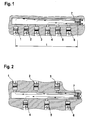
- FIG. 1 in principle, a suction device for a shown here internal combustion engine, in which Cylinders 1 to 6 of a series engine and a throttle valve 7, through which the intake of air for combustion in the cylinders 1 to 6, are indicated.
- the longest time t of the suction pulse from the cylinder 1 to the throttle valve 7 is.
- Series engine according to the figure 1 then lead the different long running times of the suction pulses of each cylinder 1 to 6 to the common collection point on the throttle valve 7th to a rather rough or even sporty sound.
- Figure 3 In an inventive arrangement of Figure 3 is between the symmetrical groups of cylinders 1 to 3 and the cylinder 4 to 6, a partition 8 is arranged, the at their the common throttle valve 7 opposite End is provided with a switching flap 9. With the from the Figure 3 to be taken switching position of the switching flap. 9 is for the group of cylinders 1 to 3 of the direct intake is closed to the throttle valve 7 and thus result here run times of the suction pulses, a series arrangement the cylinder corresponds to 3,2,1,4,5,6.
- the switching flap 9 In the other switch position to be taken from FIG the switching flap 9 have the two cylinder groups 1 to 3 and 4 to 6 symmetrical suction paths on, so that the Running times of the suction pulses in principle those of the figure 2 correspond.
Landscapes
- Engineering & Computer Science (AREA)
- Chemical & Material Sciences (AREA)
- Combustion & Propulsion (AREA)
- Mechanical Engineering (AREA)
- General Engineering & Computer Science (AREA)
- Characterised By The Charging Evacuation (AREA)
Applications Claiming Priority (2)
| Application Number | Priority Date | Filing Date | Title |
|---|---|---|---|
| DE10134850A DE10134850A1 (de) | 2001-07-17 | 2001-07-17 | Ansaugvorrichtung für einen mehrzylindrigen Verbrennungsmotor |
| DE10134850 | 2001-07-17 |
Publications (2)
| Publication Number | Publication Date |
|---|---|
| EP1277934A2 true EP1277934A2 (fr) | 2003-01-22 |
| EP1277934A3 EP1277934A3 (fr) | 2004-01-07 |
Family
ID=7692158
Family Applications (1)
| Application Number | Title | Priority Date | Filing Date |
|---|---|---|---|
| EP02015292A Withdrawn EP1277934A3 (fr) | 2001-07-17 | 2002-07-10 | Dispositif d'admission pour un moteur à combustion interne à plusieurs cylindres |
Country Status (2)
| Country | Link |
|---|---|
| EP (1) | EP1277934A3 (fr) |
| DE (1) | DE10134850A1 (fr) |
Cited By (2)
| Publication number | Priority date | Publication date | Assignee | Title |
|---|---|---|---|---|
| EP1870577A1 (fr) * | 2006-06-22 | 2007-12-26 | Ford Global Technologies, LLC | Système d'admission |
| DE102013021611A1 (de) * | 2013-12-20 | 2015-06-25 | Audi Ag | Brennkraftmaschine mit einem Saugrohr |
Citations (3)
| Publication number | Priority date | Publication date | Assignee | Title |
|---|---|---|---|---|
| JPS59183024A (ja) * | 1983-03-31 | 1984-10-18 | Mitsubishi Heavy Ind Ltd | 内燃機関の吸気管 |
| DE4041786A1 (de) | 1990-12-24 | 1992-06-25 | Opel Adam Ag | Fuer eine brennkraftmaschine bestimmte ansauganlage |
| JPH06330756A (ja) | 1993-05-25 | 1994-11-29 | Isuzu Motors Ltd | 多気筒内燃機関の吸気装置 |
Family Cites Families (5)
| Publication number | Priority date | Publication date | Assignee | Title |
|---|---|---|---|---|
| JPS61138824A (ja) * | 1984-12-10 | 1986-06-26 | Toyota Motor Corp | 多気筒内燃機関の吸気管長可変式吸気装置 |
| US4736714A (en) * | 1985-08-20 | 1988-04-12 | Mazda Motor Corporation | Engine intake system |
| US4803961A (en) * | 1985-11-19 | 1989-02-14 | Mazda Motor Corporation | Air suction devices for multicylinder engines |
| JP2877502B2 (ja) * | 1990-03-29 | 1999-03-31 | マツダ株式会社 | エンジンの吸気装置 |
| JP3217206B2 (ja) * | 1994-05-09 | 2001-10-09 | 株式会社日立製作所 | 内燃機関の吸気管 |
-
2001
- 2001-07-17 DE DE10134850A patent/DE10134850A1/de not_active Withdrawn
-
2002
- 2002-07-10 EP EP02015292A patent/EP1277934A3/fr not_active Withdrawn
Patent Citations (3)
| Publication number | Priority date | Publication date | Assignee | Title |
|---|---|---|---|---|
| JPS59183024A (ja) * | 1983-03-31 | 1984-10-18 | Mitsubishi Heavy Ind Ltd | 内燃機関の吸気管 |
| DE4041786A1 (de) | 1990-12-24 | 1992-06-25 | Opel Adam Ag | Fuer eine brennkraftmaschine bestimmte ansauganlage |
| JPH06330756A (ja) | 1993-05-25 | 1994-11-29 | Isuzu Motors Ltd | 多気筒内燃機関の吸気装置 |
Cited By (3)
| Publication number | Priority date | Publication date | Assignee | Title |
|---|---|---|---|---|
| EP1870577A1 (fr) * | 2006-06-22 | 2007-12-26 | Ford Global Technologies, LLC | Système d'admission |
| DE102013021611A1 (de) * | 2013-12-20 | 2015-06-25 | Audi Ag | Brennkraftmaschine mit einem Saugrohr |
| DE102013021611B4 (de) * | 2013-12-20 | 2018-10-31 | Audi Ag | Brennkraftmaschine mit einem Saugrohr |
Also Published As
| Publication number | Publication date |
|---|---|
| EP1277934A3 (fr) | 2004-01-07 |
| DE10134850A1 (de) | 2003-07-24 |
Similar Documents
| Publication | Publication Date | Title |
|---|---|---|
| DE69406804T2 (de) | Adaptives abgestimmtes saugrohr | |
| DE69333932T2 (de) | Zündungsteuersystem und Methode für eine Brennkraftmaschine | |
| DE68920961T2 (de) | Lufteinlasssystem für Mehrzylinderbrennkraftmaschine der V-Bauart. | |
| DE3530607A1 (de) | Ansaugsystem fuer eine mehrzylinder-brennkraftmaschine | |
| DE102012207619A1 (de) | Abgaskrümmerbaugruppe mit integriertem Abgasrückführungsbypass | |
| DE69813104T2 (de) | Vorspannvorrichtung für die Achse einer Drosselklappe in einem Einlassrohr und Vorrichtung zum Verringern des Endspiels dieser Achse | |
| DE3908475A1 (de) | Ansaugsystem fuer eine aufgeladene brennkraftmaschine | |
| DE68905179T2 (de) | Lufteinlasssystem fuer eine mehrzylinderbrennkraftmaschine. | |
| DE68916158T2 (de) | Einlassanordnung für Brennkraftmaschine mit V-förmig angeordneten Zylinderreihen. | |
| EP1049859B1 (fr) | Systeme d'aspiration pour alimenter un moteur a combustion interne en air de combustion | |
| EP0643205B1 (fr) | Système d'admission d'air d'un moteur à combustion interne | |
| DE4315129C2 (de) | Luftansaugsystem einer Brennkraftmaschine | |
| EP0490104B1 (fr) | Procédé pour contrôler l'admission d'air pour moteur à combustion interne | |
| DE3613828A1 (de) | Ansauggeraeuschdaempfer, insbesondere fuer brennkraftmaschinen | |
| DE69111110T2 (de) | Einlassanordnung für Brennkraftmaschine. | |
| DE4018612A1 (de) | Ansaugsystem fuer eine mehrzylinder-brennkraftmaschine | |
| EP1277934A2 (fr) | Dispositif d'admission pour un moteur à combustion interne à plusieurs cylindres | |
| EP1233161A2 (fr) | Système d'admission pour un moteur à combustion interne et procédé de son opération | |
| DE102005021797B4 (de) | Ansaugsystem eines Mehrzylindermotors | |
| DE102004029746B4 (de) | Sauganlage für eine Brennkraftmaschine mit mindestens zwei Zylinderbankreihen | |
| DE2451148C3 (de) | Abgasrückführeinrichtung bei Verbrennungsmotoren | |
| EP0370218B1 (fr) | Moteur à combustion interne à quatre temps | |
| DE4136206A1 (de) | Abgasanlage eines kraftfahrzeug-hubkolbenmotors | |
| DE69605198T2 (de) | Einlasssystem für verbrennungsmotoren mit mehreren zylindern | |
| DE10321323B3 (de) | Sauganlage für eine Brennkraftmaschine mit mindestens zwei Zylinderbankreihen |
Legal Events
| Date | Code | Title | Description |
|---|---|---|---|
| PUAI | Public reference made under article 153(3) epc to a published international application that has entered the european phase |
Free format text: ORIGINAL CODE: 0009012 |
|
| AK | Designated contracting states |
Kind code of ref document: A2 Designated state(s): AT BE BG CH CY CZ DE DK EE ES FI FR GB GR IE IT LI LU MC NL PT SE SK TR |
|
| AX | Request for extension of the european patent |
Free format text: AL;LT;LV;MK;RO;SI |
|
| PUAL | Search report despatched |
Free format text: ORIGINAL CODE: 0009013 |
|
| RAP1 | Party data changed (applicant data changed or rights of an application transferred) |
Owner name: MANN + HUMMEL GMBH |
|
| AK | Designated contracting states |
Kind code of ref document: A3 Designated state(s): AT BE BG CH CY CZ DE DK EE ES FI FR GB GR IE IT LI LU MC NL PT SE SK TR |
|
| AX | Request for extension of the european patent |
Extension state: AL LT LV MK RO SI |
|
| 17P | Request for examination filed |
Effective date: 20040127 |
|
| AKX | Designation fees paid |
Designated state(s): AT BE BG CH CY CZ DE DK EE ES FI FR GB GR IE IT LI LU MC NL PT SE SK TR |
|
| 17Q | First examination report despatched |
Effective date: 20061108 |
|
| 17Q | First examination report despatched |
Effective date: 20061108 |
|
| GRAP | Despatch of communication of intention to grant a patent |
Free format text: ORIGINAL CODE: EPIDOSNIGR1 |
|
| RIN1 | Information on inventor provided before grant (corrected) |
Inventor name: SPANNBAUER, HELMUT |
|
| STAA | Information on the status of an ep patent application or granted ep patent |
Free format text: STATUS: THE APPLICATION IS DEEMED TO BE WITHDRAWN |
|
| 18D | Application deemed to be withdrawn |
Effective date: 20080318 |