EP1277940A2 - Procédé et dispositif de commande d'un moteur d'entraínement - Google Patents
Procédé et dispositif de commande d'un moteur d'entraínement Download PDFInfo
- Publication number
- EP1277940A2 EP1277940A2 EP02013385A EP02013385A EP1277940A2 EP 1277940 A2 EP1277940 A2 EP 1277940A2 EP 02013385 A EP02013385 A EP 02013385A EP 02013385 A EP02013385 A EP 02013385A EP 1277940 A2 EP1277940 A2 EP 1277940A2
- Authority
- EP
- European Patent Office
- Prior art keywords
- idle
- torque
- controller
- engine
- speed
- Prior art date
- Legal status (The legal status is an assumption and is not a legal conclusion. Google has not performed a legal analysis and makes no representation as to the accuracy of the status listed.)
- Granted
Links
Images

Classifications
-
- F—MECHANICAL ENGINEERING; LIGHTING; HEATING; WEAPONS; BLASTING
- F02—COMBUSTION ENGINES; HOT-GAS OR COMBUSTION-PRODUCT ENGINE PLANTS
- F02D—CONTROLLING COMBUSTION ENGINES
- F02D41/00—Electrical control of supply of combustible mixture or its constituents
- F02D41/02—Circuit arrangements for generating control signals
- F02D41/14—Introducing closed-loop corrections
- F02D41/16—Introducing closed-loop corrections for idling
-
- F—MECHANICAL ENGINEERING; LIGHTING; HEATING; WEAPONS; BLASTING
- F02—COMBUSTION ENGINES; HOT-GAS OR COMBUSTION-PRODUCT ENGINE PLANTS
- F02D—CONTROLLING COMBUSTION ENGINES
- F02D37/00—Non-electrical conjoint control of two or more functions of engines, not otherwise provided for
- F02D37/02—Non-electrical conjoint control of two or more functions of engines, not otherwise provided for one of the functions being ignition
-
- F—MECHANICAL ENGINEERING; LIGHTING; HEATING; WEAPONS; BLASTING
- F02—COMBUSTION ENGINES; HOT-GAS OR COMBUSTION-PRODUCT ENGINE PLANTS
- F02D—CONTROLLING COMBUSTION ENGINES
- F02D2200/00—Input parameters for engine control
- F02D2200/02—Input parameters for engine control the parameters being related to the engine
- F02D2200/10—Parameters related to the engine output, e.g. engine torque or engine speed
- F02D2200/1006—Engine torque losses, e.g. friction or pumping losses or losses caused by external loads of accessories
-
- F—MECHANICAL ENGINEERING; LIGHTING; HEATING; WEAPONS; BLASTING
- F02—COMBUSTION ENGINES; HOT-GAS OR COMBUSTION-PRODUCT ENGINE PLANTS
- F02D—CONTROLLING COMBUSTION ENGINES
- F02D2200/00—Input parameters for engine control
- F02D2200/60—Input parameters for engine control said parameters being related to the driver demands or status
- F02D2200/602—Pedal position
-
- F—MECHANICAL ENGINEERING; LIGHTING; HEATING; WEAPONS; BLASTING
- F02—COMBUSTION ENGINES; HOT-GAS OR COMBUSTION-PRODUCT ENGINE PLANTS
- F02D—CONTROLLING COMBUSTION ENGINES
- F02D2250/00—Engine control related to specific problems or objectives
- F02D2250/18—Control of the engine output torque
-
- F—MECHANICAL ENGINEERING; LIGHTING; HEATING; WEAPONS; BLASTING
- F02—COMBUSTION ENGINES; HOT-GAS OR COMBUSTION-PRODUCT ENGINE PLANTS
- F02D—CONTROLLING COMBUSTION ENGINES
- F02D2250/00—Engine control related to specific problems or objectives
- F02D2250/18—Control of the engine output torque
- F02D2250/21—Control of the engine output torque during a transition between engine operation modes or states
Definitions
- the invention relates to a method and a device for operating a drive motor of a motor vehicle.
- Control systems used with the help of the the performance parameters that can be set on the drive motor depend be determined by input variables.
- Some of these electronic control systems work on the basis of a Torque structure, i.e. from the driver and, if applicable, from additional systems, like cruise control, electronic stability programs, Transmission controls, etc., are used as setpoints torque values specified for the control system, the from the control system considering other sizes in setting variables for the performance parameter (s) Drive motor are implemented.
- An example of one Torque structure is from DE 42 39 711 A1 (US patent 5 558 178).
- the idle controller component By connecting the idle controller component to the resulting one Target torque after coordination of Driver request torque and target torque of other control systems as well as through the detachment controlled depending on the size of the company of the idle controller contribution, it enables the idle control to optimally fit into a moment structure that can be used regardless of the motor type. torque structure and the replacement or reinstallation of the Idle controller when transitioning from idle to non-idle can therefore be carried out in the same way for all engine types become.
- a time-controlled detachment is particularly advantageous the contribution of the idle controller when the accelerator pedal is pressed. This is because after a limited time Transition process no change or influence the engine torque by idle controller more. In particular jumps in momentum that affect driving comfort and that through different physical Translation of the idle control torque via the transmission arise avoided.
- the engine speed-dependent is advantageous in the context of an alternative solution Replacement of the idle controller fee.
- a speed threshold here too the desired property becomes more constant Translation changes achieved.
- the influencing function of the Idle controller dependent on other operating parameters, e.g. Motor temperature, outside temperature, air pressure, etc.
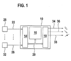
- Figure 1 shows an overview of a control device for operation of a drive motor
- FIG Flowchart a preferred embodiment of a torque structure in connection with the control of a drive motor is shown, provided it is with a view to the described Approach is important.
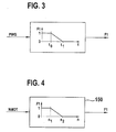
- Figures 3 and 4 show two preferred embodiments for formation a correction factor, with the help of which the idle controller influenced in the transition between idle and non-idle becomes.
- FIG. 1 shows a block diagram of a control device to control a drive motor, especially one Internal combustion engine.
- a control unit 10 is provided which as components an input circuit 14, at least has a computer unit 16 and an output circuit 18.
- a communication system 20 connects these components for mutual data exchange.
- the input circuit 14 of the control unit 10 become input lines 22 to 26 supplied, which in a preferred embodiment are designed as a bus system and via that of the control unit 10 signals are supplied, which are used to control the drive motor Represent the operating variables to be evaluated. These signals are recorded by measuring devices 28 to 32.
- such operating variables are one Internal combustion engine accelerator pedal position, engine speed, engine load, Exhaust gas composition, engine temperature, etc.
- About the Output circuit 18 controls the control unit 10 the power of the drive motor.
- FIG Output lines 34, 36 and 38 symbolize via which the fuel mass to be injected, the ignition angle and at least one electrically operated throttle valve Adjustment of the air supply can be operated.
- About the illustrated Paths become the air supply to the internal combustion engine, the firing angle of each cylinder, the one to be injected Fuel mass, the injection timing and / or the air / fuel ratio, etc. is set.
- Further further control systems of the vehicle can be provided, the input circuit 14 default sizes, for example Transmit torque setpoints.
- Such control systems are, for example, traction control systems, vehicle dynamics controls, Transmission controls, engine drag torque controls, Speed controller, speed limiter, etc.
- control system will also be equipped with alternative drive concepts, e.g. Electric motors used.
- an idle controller intended to maintain engine operation when not pedaling Accelerator pedal and low speed. This determines, for example, depending on the Speed deviation between a target and an actual speed using a specified controller strategy (e.g. proportional, Integral and / or differential component) one Contribution (e.g. torque change quantity or setpoint torque) that to the resulting target torque value for the drive motor is activated. In the preferred embodiment this intrusion is carried out as an addition. In other embodiments the idle contribution is e.g. normalized so that the connection is made by means of multiplication.
- the idle controller is connected to the resulting one Target torque, which is coordinated by the driver's desired torque and the target torques of other control systems, external and, if necessary, internal default values are formed. Thereby becomes an influencing of the wheel torque as mentioned above avoided by the idle controller, so that wheel torque constant Translation changes can be achieved.
- Pressing the accelerator pedal is in the preferred embodiment a temporary process started, during the time-dependent idle controller contribution continuously is withdrawn to zero.
- a factor is formed depending on the time, which starts with one after a given one has expired Time period takes the value zero and with the idle controller contribution is weighted (multiplied). After expiration the idle controller contribution is the specified time period Zero.
- the accelerator pedal is released, if this is its idle position this factor is preferred Embodiment suddenly set to one to Idle regulators give the opportunity to maintain immediately of the engine operation.
- a time-dependent control is also exemplary here of the idle controller contribution, with the Factor increases from zero to one.
- the time periods for detachment and switching on the idle controller are preferred different, one when switching on the controller a shorter time period is selected than for the replacement.
- An alternative solution shows a corresponding replacement of the Idle controller depending on the speed instead of the time.
- the idle controller contribution increases with increasing speed drove to zero, in the preferred embodiment the factor mentioned above corresponds to a speed-dependent Characteristic curve is formed.
- the factor mentioned above corresponds to a speed-dependent Characteristic curve is formed.
- sinking Engine speed a speed-dependent adjustment of the idle controller contribution according to the same or a different one Characteristic curve provided, the above-mentioned factor accordingly is formed.
- Another alternative is that of the idle controller output signal maximum and minimum value limits assigned to which the signal is limited.
- the detachment or control is then manipulated by these limits realized, with e.g. the maximum value preferably time-dependent or speed-dependent on the Value zero is controlled, and / or the minimum value to the Value zero is controlled.
- the control is reversed method.
- the flow chart shown in Figure 2 describes a Program of a microcomputer of the control unit 10, wherein the individual blocks of the representation of FIG. 2 programs, Represent program parts or program steps while the Connection lines represent the signal flow. It can the first part up to the vertical, dashed line in a first control unit, also there in a microcomputer, expire while the part in after that line a second control unit runs.
- signals are supplied which correspond to the vehicle speed VFZG and the accelerator pedal position PWG correspond. These variables are in a map 100 in a torque request implemented by the driver.
- This driver request moment which is a default size for a moment on the output side represents the transmission or for a wheel torque, one Correction stage 102 supplied. This correction is preferred an addition or subtraction.
- the driver request moment is determined by a weighted loss moment Corrected MKORR, which was formed in node 104 has been. In this is the supplied, by means of Translation Ü in the drive train and possibly further translations in the drive train on the output side of the gearbox Moment after the transmission, preferably a wheel torque converted Loss moment MVER weighted by a factor F3.
- the weighting is preferably carried out as a multiplication.
- the Factor F3 is in 106 from the accelerator pedal position representing Size PWG and possibly also the engine speed representative size NMOT formed.
- a first Maximum value selection stage 108 is the maximum value from the driver's desired torque MFA and the default torque MFGR of a cruise control selected. This maximum value is to a subsequent minimum value stage 110, in which the smaller of this value and the target torque value MESP an electronic stability program is selected.
- the output variable of the minimum value stage 110 represents a torque variable output side of the transmission or a wheel torque size represents by taking into account the gear ratio Ü and, if necessary, further translations in the drive train converted into a torque size on the output side of the gearbox which is on the transmission input side or output side of the drive motor is present.
- This moment size is in one another coordinator 112 with the target torque MGETR one Transmission control coordinated.
- the target torque of the transmission control is formed according to the needs of the switching process.
- the resulting setpoint torque MSOLLRES then becomes the larger one the torque values minimum torque MMIN and the output torque coordination level 112.
- the minimum moment is in a preferred embodiment from the Torque loss derived.
- the moment coordination is only exemplary above shown.
- one or the other other default torque not used for coordination or other default torques are provided, for example a moment of a maximum speed limit, one Engine speed limitation, etc.
- Target torque is supplied to a correction stage 116 in which the target torque with the engine to apply, not that Corrected loss torques available becomes.
- the loss moments MVER are possibly in a weighting level 118 weighted with a factor F2. This is depending on the version constant (also 1) or depending on the company size, e.g. engine speed-dependent.
- the loss moments MVER themselves become the torque requirement in the addition stage 120 MNA of auxiliary units and the engine loss torque MVERL formed.
- the determination of these sizes is from the Known in the prior art, the torque requirement depending depending on the operating status of the respective auxiliary unit of characteristic curves or the like, the engine loss moments determined depending on engine speed and engine temperature becomes.
- the loss torque MVER formed in this way becomes then provided to correction stage 104, where a conversion of the torque loss using the known Gearbox transmission Ü as well as further translations in the Drive train on the output side of the gearbox on the plane the transmission output or wheel torque occurs.
- correction stage 116 which in the preferred Embodiment represents an addition is a default size for that to be generated by the drive unit Torque for the drive taking into account the inner Losses and for the operation of auxiliary units (e.g. Air conditioning compressor) necessary torque (indicated engine torque).
- This default torque is in a further correction stage 122 with the weighted in a correction stage 124 Output variable DMLLR of the idle controller corrected (preferably added).
- the weighting factor F1 with which the Output variable of the idle controller is included depending on speed and / or time, when leaving the Idle range the factor temporally or with increasing Engine speed decreases to zero.
- the default size is MISOLL then in 126 as known from the prior art in manipulated variables for setting the performance parameters of the drive motor implemented, in the case of a gasoline engine in Air supply, fuel injection and ignition angle, in the case a diesel engine in fuel quantity.
- the idle controller intervenes in the direction of action after moment coordination (108 to 114) in the torque specification in which it corresponds to its output signal the resulting target torque MSOLLRES is corrected.
- the correction is complete in the idle controller area.
- the idle controller output with a factor F1 weighted, which over time after pressing the Accelerator pedal or speed-dependent from one to zero. If the factor is zero, there is no idle controller component more activated.
- the idle controller itself can do this continue to be active according to the design and according to the speed ratios run to its limit or through Time control of the integral part, by zero enforce proportional and differential portion or Partially fixing the integral part to the current value or be stopped entirely.
- the idle controller is further by the connection the loss moments MVER piloted in 116.
- the loss moments MVER piloted is missing, so that Idle controller the total loss moments and the demand adjusts the auxiliary units.
- the loss torque feedforward control by a factor To weight F2 which is complementary to the curtailment of the Idle controller contribution is raised. That means in that Dimensions by the weighting of the idle controller contribution in 124 this decreases, decreases by corresponding opposite Weighting the precontrol in step 118 increases this.
- FIG. 3 A first solution is shown in FIG. 3. there the factor F1 is triggered by actuation of the accelerator pedal (signal PWG> 0) from its value one to Reduced value zero.
- An example is shown in Figure 3, in which the reduction is carried out linearly.
- other time functions for example exponential, step-like time functions, etc. used.
- the pedal is operated at time T0, after a certain predetermined period of time At time T1, factor F1 is then reduced to zero. This means a complete disappearance of the effect of the idle controller as part of the torque control.
- the pedal is released, i.e. the drive motor returns back into idle mode, the idle controller part 1 in one embodiment again depending on time headed for its full value.
- a second embodiment is shown in FIG. 4.
- a characteristic curve 150 which is the engine speed NMOT is fed.
- the factor F1 plotted against engine speed.
- N1 a speed that is just above the idle speed (e.g. 900 revolutions per minute) while the second speed N2 a higher speed of e.g. 1500 revolutions represents per minute.
- the characteristic 150 becomes the value of the factor F1 read out, which then has the effect according to its size of the idle controller as part of the torque control shown weighted.
- the speed returns to the range the speeds N1 and N2 back, so the idle controller portion in one embodiment depending on the speed headed back to its full value.
- the speed-dependent change of the idle controller signal not the engine speed, but one, e.g. to the idle target speed, standardized size used. This is beneficial when using an operating state dependent (standardized) Speed threshold for the idle control, whose Activate when this speed threshold is undershot the (normalized) engine speed occurs.
Landscapes
- Engineering & Computer Science (AREA)
- Chemical & Material Sciences (AREA)
- Combustion & Propulsion (AREA)
- Mechanical Engineering (AREA)
- General Engineering & Computer Science (AREA)
- Control Of Vehicle Engines Or Engines For Specific Uses (AREA)
- Electrical Control Of Air Or Fuel Supplied To Internal-Combustion Engine (AREA)
- Hybrid Electric Vehicles (AREA)
- Combined Controls Of Internal Combustion Engines (AREA)
Applications Claiming Priority (2)
| Application Number | Priority Date | Filing Date | Title |
|---|---|---|---|
| DE2001135143 DE10135143A1 (de) | 2001-07-19 | 2001-07-19 | Verfahren und Vorrichtung zum Betreiben eines Antriebsmotors |
| DE10135143 | 2001-07-19 |
Publications (3)
| Publication Number | Publication Date |
|---|---|
| EP1277940A2 true EP1277940A2 (fr) | 2003-01-22 |
| EP1277940A3 EP1277940A3 (fr) | 2006-05-03 |
| EP1277940B1 EP1277940B1 (fr) | 2008-05-28 |
Family
ID=7692341
Family Applications (1)
| Application Number | Title | Priority Date | Filing Date |
|---|---|---|---|
| EP20020013385 Expired - Lifetime EP1277940B1 (fr) | 2001-07-19 | 2002-06-19 | Procédé et dispositif de commande d'un moteur d'entraînement |
Country Status (3)
| Country | Link |
|---|---|
| EP (1) | EP1277940B1 (fr) |
| JP (1) | JP2003049693A (fr) |
| DE (2) | DE10135143A1 (fr) |
Cited By (7)
| Publication number | Priority date | Publication date | Assignee | Title |
|---|---|---|---|---|
| WO2005056996A1 (fr) * | 2003-12-11 | 2005-06-23 | Robert Bosch Gmbh | Procede et dispositif de fonctionnement d'une unite d'entrainement |
| EP1630391A1 (fr) * | 2004-08-27 | 2006-03-01 | Siemens Aktiengesellschaft | Procédé et dispositif pour la determination d'un couple de sortie |
| FR2927281A1 (fr) * | 2008-02-11 | 2009-08-14 | Renault Sas | Procede de regulation automatique du couple moteur pendant les phases de glissement symetrique des roues motrices d'un vehicule et dispositif pour la mise en oeuvre de ce procede |
| DE102011004862A1 (de) | 2011-02-28 | 2012-08-30 | Bayerische Motoren Werke Aktiengesellschaft | Bestimmen von Rad- und/oder Achsmomentvorgaben in einem Kraftfahrzeug |
| DE102011005962A1 (de) | 2011-03-23 | 2012-09-27 | Bayerische Motoren Werke Aktiengesellschaft | Aufteilen einer Momentenanforderung auf zwei von unterschiedlichen Motoren angetriebenen Antriebsachsen eines Kraftfahrzeugs |
| CN112196677A (zh) * | 2020-10-10 | 2021-01-08 | 东风康明斯发动机有限公司 | 一种发电用电控柴油机的转速控制系统 |
| CN112428982A (zh) * | 2019-08-07 | 2021-03-02 | 纬湃科技投资(中国)有限公司 | 混合动力汽车油门踏板信号处理方法 |
Families Citing this family (3)
| Publication number | Priority date | Publication date | Assignee | Title |
|---|---|---|---|---|
| US8099229B2 (en) | 2008-03-03 | 2012-01-17 | GM Global Technology Operations LLC | Method and apparatus for limiting wheel slip |
| DE102011120792A1 (de) * | 2011-12-10 | 2013-06-13 | Gm Global Technology Operations, Llc | Verfahren zum Steuern und Steuerschaltung eines Verbrennungsmotors eines Kraftfahrzeuges |
| DE102017200296A1 (de) * | 2017-01-10 | 2018-07-12 | Volkswagen Aktiengesellschaft | Motorsteuerung, Motorsteuerungsverfahren und entsprechendes Computerprogramm |
Citations (1)
| Publication number | Priority date | Publication date | Assignee | Title |
|---|---|---|---|---|
| DE4239711A1 (de) | 1992-11-26 | 1994-06-01 | Bosch Gmbh Robert | Verfahren und Vorrichtung zur Steuerung eines Fahrzeugs |
Family Cites Families (3)
| Publication number | Priority date | Publication date | Assignee | Title |
|---|---|---|---|---|
| DE4100380A1 (de) * | 1991-01-09 | 1992-07-16 | Vdo Schindling | Verfahren zum betreiben einer drosselklappengeregelten brennkraftmaschine im leerlaufregelbereich |
| US5901682A (en) * | 1997-12-19 | 1999-05-11 | Caterpillar Inc. | Method for transitioning between different operating modes of an internal combustion engine |
| US6119063A (en) * | 1999-05-10 | 2000-09-12 | Ford Global Technologies, Inc. | System and method for smooth transitions between engine mode controllers |
-
2001
- 2001-07-19 DE DE2001135143 patent/DE10135143A1/de not_active Withdrawn
-
2002
- 2002-06-19 DE DE50212311T patent/DE50212311D1/de not_active Expired - Lifetime
- 2002-06-19 EP EP20020013385 patent/EP1277940B1/fr not_active Expired - Lifetime
- 2002-07-03 JP JP2002194348A patent/JP2003049693A/ja active Pending
Patent Citations (2)
| Publication number | Priority date | Publication date | Assignee | Title |
|---|---|---|---|---|
| DE4239711A1 (de) | 1992-11-26 | 1994-06-01 | Bosch Gmbh Robert | Verfahren und Vorrichtung zur Steuerung eines Fahrzeugs |
| US5558178A (en) | 1992-11-26 | 1996-09-24 | Robert Bosch Gmbh | Method and arrangement for controlling a motor vehicle |
Cited By (10)
| Publication number | Priority date | Publication date | Assignee | Title |
|---|---|---|---|---|
| WO2005056996A1 (fr) * | 2003-12-11 | 2005-06-23 | Robert Bosch Gmbh | Procede et dispositif de fonctionnement d'une unite d'entrainement |
| EP1630391A1 (fr) * | 2004-08-27 | 2006-03-01 | Siemens Aktiengesellschaft | Procédé et dispositif pour la determination d'un couple de sortie |
| FR2927281A1 (fr) * | 2008-02-11 | 2009-08-14 | Renault Sas | Procede de regulation automatique du couple moteur pendant les phases de glissement symetrique des roues motrices d'un vehicule et dispositif pour la mise en oeuvre de ce procede |
| DE102011004862A1 (de) | 2011-02-28 | 2012-08-30 | Bayerische Motoren Werke Aktiengesellschaft | Bestimmen von Rad- und/oder Achsmomentvorgaben in einem Kraftfahrzeug |
| WO2012116896A1 (fr) | 2011-02-28 | 2012-09-07 | Bayerische Motoren Werke Aktiengesellschaft | Détermination d'un couple aux roues et/ou d'un couple aux essieux prédéfini dans un véhicule automobile |
| DE102011005962A1 (de) | 2011-03-23 | 2012-09-27 | Bayerische Motoren Werke Aktiengesellschaft | Aufteilen einer Momentenanforderung auf zwei von unterschiedlichen Motoren angetriebenen Antriebsachsen eines Kraftfahrzeugs |
| DE102011005962B4 (de) | 2011-03-23 | 2023-07-27 | Bayerische Motoren Werke Aktiengesellschaft | Aufteilen einer Momentenanforderung auf zwei von unterschiedlichen Motoren angetriebenen Antriebsachsen eines Kraftfahrzeugs |
| CN112428982A (zh) * | 2019-08-07 | 2021-03-02 | 纬湃科技投资(中国)有限公司 | 混合动力汽车油门踏板信号处理方法 |
| CN112196677A (zh) * | 2020-10-10 | 2021-01-08 | 东风康明斯发动机有限公司 | 一种发电用电控柴油机的转速控制系统 |
| CN112196677B (zh) * | 2020-10-10 | 2022-11-29 | 东风康明斯发动机有限公司 | 一种发电用电控柴油机的转速控制系统 |
Also Published As
| Publication number | Publication date |
|---|---|
| DE10135143A1 (de) | 2003-01-30 |
| JP2003049693A (ja) | 2003-02-21 |
| DE50212311D1 (de) | 2008-07-10 |
| EP1277940B1 (fr) | 2008-05-28 |
| EP1277940A3 (fr) | 2006-05-03 |
Similar Documents
| Publication | Publication Date | Title |
|---|---|---|
| DE4239711B4 (de) | Verfahren und Vorrichtung zur Steuerung eines Fahrzeugs | |
| EP1272752B1 (fr) | Procede et dispositif pour la commande de l'unite d'entrainement d'un vehicule automobile | |
| EP1412630B1 (fr) | Procede et dispositif d'utilisation d'un moteur d'entrainement d'un vehicule | |
| EP1277940B1 (fr) | Procédé et dispositif de commande d'un moteur d'entraînement | |
| EP1005609B1 (fr) | Procede permettant de commander le recyclage des gaz d'echappement d'un moteur a combustion interne | |
| WO2001044644A2 (fr) | Procede et dispositif pour assurer la commande de l"unite d"entrainement d"un vehicule | |
| EP1432899B1 (fr) | Procede et dispositif pour l'exploitation d'un moteur d'entrainement d'un vehicule | |
| EP1077827B1 (fr) | Dispositif de commande de moteur de vehicule avec regulation et/ou limitation de la vitesse de roulement | |
| DE10048015A1 (de) | Verfahren und Vorrichtung zur Steuerung der Antriebseinheit eines Fahrzeugs | |
| DE3400951A1 (de) | Verfahren und vorrichtung zur drehzahlregelung bei einer brennkraftmaschine | |
| EP1242732B1 (fr) | Procede et dispositif de commande de l'unite d'entrainement d'un vehicule | |
| DE10148343A1 (de) | Verfahren und Vorrichtung zur Steuerung einer Antriebseinheit | |
| DE4313746A1 (de) | Verfahren und Vorrichtung zur Steuerung der Leistung einer Antriebseinheit eines Fahrzeugs | |
| DE4223253A1 (de) | Steuereinrichtung für ein Fahrzeug | |
| DE4426972B4 (de) | Verfahren und Vorrichtung zur Steuerung einer Brennkraftmaschine | |
| DE4335726A1 (de) | Verfahren und Vorrichtung zur Steuerung der Antriebsleistung eines Fahrzeugs | |
| DE10305092B4 (de) | Verfahren zur automatischen Anpassung eines Drehmomentenmodells sowie Schaltungsanordnung | |
| DE19741565A1 (de) | Verfahren und Vorrichtung zur Steuerung einer Brennkraftmaschine | |
| EP1474598B1 (fr) | Dispositif pour reguler le moment de rotation d'une unite d'entrainement d'un vehicule | |
| DE10039784A1 (de) | Verfahren und Vorrichtung zum Betreiben einer Brennkraftmaschine | |
| DE10150421A1 (de) | Verfahren und Vorrichtung zur Steuerung der Geschwindigkeit eines Fahrzeugs | |
| DE10253004B4 (de) | Verfahren zum Betreiben einer Brennkraftmaschine, insbesondere eines Kraftfahrzeugs, Computerprogramm, Speicher, Steuergerät und Brennkraftmaschine | |
| WO1997043533A1 (fr) | Procede et dispositif permettant d'assurer la commande d'un moteur a combustion interne | |
| EP2254781B1 (fr) | Procédé et dispositif pour la commande d'un véhicule à entraînement hybride | |
| DE10148342A1 (de) | Verfahren und Vorrichtung zum Betreiben einer Antriebseinheit eines Fahrzeugs |
Legal Events
| Date | Code | Title | Description |
|---|---|---|---|
| PUAI | Public reference made under article 153(3) epc to a published international application that has entered the european phase |
Free format text: ORIGINAL CODE: 0009012 |
|
| AK | Designated contracting states |
Kind code of ref document: A2 Designated state(s): AT BE CH CY DE DK ES FI FR GB GR IE IT LI LU MC NL PT SE TR |
|
| AX | Request for extension of the european patent |
Free format text: AL;LT;LV;MK;RO;SI |
|
| PUAL | Search report despatched |
Free format text: ORIGINAL CODE: 0009013 |
|
| AK | Designated contracting states |
Kind code of ref document: A3 Designated state(s): AT BE CH CY DE DK ES FI FR GB GR IE IT LI LU MC NL PT SE TR |
|
| AX | Request for extension of the european patent |
Extension state: AL LT LV MK RO SI |
|
| 17P | Request for examination filed |
Effective date: 20061103 |
|
| AKX | Designation fees paid |
Designated state(s): DE FR IT SE |
|
| 17Q | First examination report despatched |
Effective date: 20070716 |
|
| GRAP | Despatch of communication of intention to grant a patent |
Free format text: ORIGINAL CODE: EPIDOSNIGR1 |
|
| GRAS | Grant fee paid |
Free format text: ORIGINAL CODE: EPIDOSNIGR3 |
|
| GRAA | (expected) grant |
Free format text: ORIGINAL CODE: 0009210 |
|
| AK | Designated contracting states |
Kind code of ref document: B1 Designated state(s): DE FR IT SE |
|
| REF | Corresponds to: |
Ref document number: 50212311 Country of ref document: DE Date of ref document: 20080710 Kind code of ref document: P |
|
| REG | Reference to a national code |
Ref country code: SE Ref legal event code: TRGR |
|
| PGFP | Annual fee paid to national office [announced via postgrant information from national office to epo] |
Ref country code: FR Payment date: 20080618 Year of fee payment: 7 Ref country code: IT Payment date: 20080626 Year of fee payment: 7 |
|
| PGFP | Annual fee paid to national office [announced via postgrant information from national office to epo] |
Ref country code: SE Payment date: 20080624 Year of fee payment: 7 |
|
| PLBE | No opposition filed within time limit |
Free format text: ORIGINAL CODE: 0009261 |
|
| STAA | Information on the status of an ep patent application or granted ep patent |
Free format text: STATUS: NO OPPOSITION FILED WITHIN TIME LIMIT |
|
| 26N | No opposition filed |
Effective date: 20090303 |
|
| REG | Reference to a national code |
Ref country code: FR Ref legal event code: ST Effective date: 20100226 |
|
| PG25 | Lapsed in a contracting state [announced via postgrant information from national office to epo] |
Ref country code: FR Free format text: LAPSE BECAUSE OF NON-PAYMENT OF DUE FEES Effective date: 20090630 |
|
| PG25 | Lapsed in a contracting state [announced via postgrant information from national office to epo] |
Ref country code: IT Free format text: LAPSE BECAUSE OF NON-PAYMENT OF DUE FEES Effective date: 20090619 |
|
| PG25 | Lapsed in a contracting state [announced via postgrant information from national office to epo] |
Ref country code: SE Free format text: LAPSE BECAUSE OF NON-PAYMENT OF DUE FEES Effective date: 20090620 |
|
| PGFP | Annual fee paid to national office [announced via postgrant information from national office to epo] |
Ref country code: DE Payment date: 20160810 Year of fee payment: 15 |
|
| REG | Reference to a national code |
Ref country code: DE Ref legal event code: R119 Ref document number: 50212311 Country of ref document: DE |
|
| PG25 | Lapsed in a contracting state [announced via postgrant information from national office to epo] |
Ref country code: DE Free format text: LAPSE BECAUSE OF NON-PAYMENT OF DUE FEES Effective date: 20180103 |