EP1277963B1 - Compresseur à gaz avec élément séparateur d'huile - Google Patents
Compresseur à gaz avec élément séparateur d'huile Download PDFInfo
- Publication number
- EP1277963B1 EP1277963B1 EP20010306088 EP01306088A EP1277963B1 EP 1277963 B1 EP1277963 B1 EP 1277963B1 EP 20010306088 EP20010306088 EP 20010306088 EP 01306088 A EP01306088 A EP 01306088A EP 1277963 B1 EP1277963 B1 EP 1277963B1
- Authority
- EP
- European Patent Office
- Prior art keywords
- discharge
- cooling medium
- high pressure
- compressor
- pressure cooling
- Prior art date
- Legal status (The legal status is an assumption and is not a legal conclusion. Google has not performed a legal analysis and makes no representation as to the accuracy of the status listed.)
- Expired - Lifetime
Links
- 239000002826 coolant Substances 0.000 claims description 85
- 239000000314 lubricant Substances 0.000 claims description 39
- 238000000926 separation method Methods 0.000 claims description 29
- 230000006835 compression Effects 0.000 claims description 25
- 238000007906 compression Methods 0.000 claims description 25
- 238000004891 communication Methods 0.000 claims description 9
- 238000007599 discharging Methods 0.000 claims description 8
- 238000012360 testing method Methods 0.000 description 17
- 238000001816 cooling Methods 0.000 description 16
- 238000011835 investigation Methods 0.000 description 11
- 230000000052 comparative effect Effects 0.000 description 8
- 230000003247 decreasing effect Effects 0.000 description 6
- 239000002184 metal Substances 0.000 description 4
- 230000015556 catabolic process Effects 0.000 description 3
- 238000006731 degradation reaction Methods 0.000 description 3
- 238000004519 manufacturing process Methods 0.000 description 3
- 239000003595 mist Substances 0.000 description 3
- 238000004378 air conditioning Methods 0.000 description 2
- 238000005259 measurement Methods 0.000 description 2
- 235000014676 Phragmites communis Nutrition 0.000 description 1
- 230000007547 defect Effects 0.000 description 1
- 238000013461 design Methods 0.000 description 1
- 230000002542 deteriorative effect Effects 0.000 description 1
- 238000010438 heat treatment Methods 0.000 description 1
- 239000000203 mixture Substances 0.000 description 1
- 238000005057 refrigeration Methods 0.000 description 1
- 238000004781 supercooling Methods 0.000 description 1
Images



Classifications
-
- F—MECHANICAL ENGINEERING; LIGHTING; HEATING; WEAPONS; BLASTING
- F04—POSITIVE - DISPLACEMENT MACHINES FOR LIQUIDS; PUMPS FOR LIQUIDS OR ELASTIC FLUIDS
- F04C—ROTARY-PISTON, OR OSCILLATING-PISTON, POSITIVE-DISPLACEMENT MACHINES FOR LIQUIDS; ROTARY-PISTON, OR OSCILLATING-PISTON, POSITIVE-DISPLACEMENT PUMPS
- F04C29/00—Component parts, details or accessories of pumps or pumping installations, not provided for in groups F04C18/00 - F04C28/00
- F04C29/02—Lubrication; Lubricant separation
- F04C29/026—Lubricant separation
-
- F—MECHANICAL ENGINEERING; LIGHTING; HEATING; WEAPONS; BLASTING
- F04—POSITIVE - DISPLACEMENT MACHINES FOR LIQUIDS; PUMPS FOR LIQUIDS OR ELASTIC FLUIDS
- F04B—POSITIVE-DISPLACEMENT MACHINES FOR LIQUIDS; PUMPS
- F04B39/00—Component parts, details, or accessories, of pumps or pumping systems specially adapted for elastic fluids, not otherwise provided for in, or of interest apart from, groups F04B25/00 - F04B37/00
- F04B39/16—Filtration; Moisture separation
Definitions
- the present invention relates to a gas compressor assembled into an air-conditioning system for a vehicle or the like, and more particularly to a gas compressor in which it is possible to reduce a cost for the overall compressor without deteriorating its oil component separating function that is needed for the compressor, and to keep the oil component separating function constant for a long period of time.
- a cylinder 2 having a substantially oval-shaped inner circumference is provided within a compressor case 1 and side blocks 3 and 4 are mounted at both end faces of the cylinder 2.
- the compressor case 1 is formed of a box body 1-1 of one-end open type and a front head 1-2 mounted at the opening end thereof.
- a second discharge chamber 5 and the suction chamber 6 are provided within this compressor case 1.
- the second discharge chamber 5 is provided between an inside sealed end (the inside sealed end of the box body 1-1) of the above-described compressor case 1 and one of the side blocks 3, and also, the suction chamber 6 is provided between the inner surface side of the front head 1-2 and the side block of the other side 4, respectively.
- a rotor 7 is laterally provided inside the cylinder 2.
- the rotor 7 is supported rotatably through bearings 9 of the side blocks 3 and 4 and a rotor shaft 8 extending along the axis thereof.
- a plurality of slit-like vane grooves 11 are formed radially on the outer circumferential surface side of the rotor 7.
- Vanes 12 are mounted on these vane grooves 11 one by one.
- the vanes 12 are provided to be retractable and projectable from the outer circumferential surface of the rotor 7 toward the inner wall of the cylinder 2.
- the interior of the cylinder 2 is partitioned into a plurality of small chambers by both surfaces at a tip end of each vane 12, outer circumferential surface of the rotor 7, inner surfaces of the side blocks 3 and 4 and the inner wall of the cylinder 2.
- the small chamber thus partitioned is a compression chamber 13.
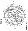
- Such a compression chamber 13 within the cylinder 2 is rotated in a direction indicated by an arrow a in Fig. 12 to repeats the change in volume.
- the high pressure cooling medium gas within a compression chamber 13 is discharged to a first discharge chamber 18 of the outer space of the cylinder 1 from the cylinder discharge port 16 and further introduced through a gas passage 19 and an oil separator 20 to the side of the second discharge chamber 5.
- lubricant is contained in the form of mist in the high pressure cooling medium gas discharged to the first discharge chamber 18.
- the lubricant oil component is separated by the collision with the oil separating filter 21 composed of metal mesh or the like for the oil separator 20.
- the lubricant oil component thus separated is dropped and reserved in an oil sump 22 of the bottom portion of the second discharge chamber 5.
- the pressure of the high pressure cooling medium gas discharged into the second discharge chamber 5 is applied to the oil sump 22.
- the oil in the oil sump 22 to which such discharge pressure Pd is applied is fed to a back pressure chamber 25 of the bottom portion of the vane 12 passing through the side blocks 3 and 4, an oil hole 23 of the cylinder 1, the gap of the bearing 9 and a supply groove 24 formed in the surfaces, facing each other, of the side blocks 3 and 4 in this order.
- the side block 3 and the oil separator 20 are formed as discrete parts in view of the relationship of the structure in which the gas passage 19 for introducing to the oil separator 20 side the high pressure cooling medium gas containing the lubricant is formed between the mounting alignment surfaces of the side block 3 and the oil separator 20.
- the side block 3 and the oil separator 20 are formed as discrete parts in view of the relationship of the structure in which the gas passage 19 for introducing to the oil separator 20 side the high pressure cooling medium gas containing the lubricant is formed between the mounting alignment surfaces of the side block 3 and the oil separator 20.
- an oil separator fastening bolt 26 see Fig. 13
- a seal member for the mounting portion or the like be required, but also the assembling step for assembling the oil separator 20 to the side block 3 in the compressor manufacturing line.
- the oil separator 20 is fixed to the side block 3 by oil separator fastening bolts 26. Accordingly, if there is a defect due to the loosening of the oil separator fastening bolts 26, for example, when the loosening of the oil separator bolts 26, the mounting alignment surfaces of the side block 3 and the oil separator 20 are opened to split the gas passage 19, the high pressure cooling medium gas before the oil separation leaks to the outside of the gas passage 19 from the crack to cause the reduction of the oil separation property or the like. That is, there is a problem in that it is difficult to keep the constant oil separation function for a long period of time.
- US 3776668 discloses a separator for a refrigeration compressor in which a gas/lubricant oil mixture is passed through a plurality of chambers with baffle and oil coalescing structures between them in order to separate out the oil before the gas is passed through a discharge port outside the compressor casing.
- a first object of the present invention is to provide a gas compressor that is suitable for reducing cost for overall equipment while attaining the reduction of the numbers of assembling steps and the parts relating to the oil separator
- a second object thereof is to provide a gas compressor provided with an oil separator that is high in reliability to make it possible to keep a constant oil separation function that is needed for the compressor for a long period of time.
- a gas compressor having a compressor case, which has an inner wall portion at an inner sealed end thereof, a cylinder disposed in the compressor case, a pair of side blocks mounted on end surfaces of the cylinder, a compression chamber disposed in the cylinder for receiving a high pressure cooling medium gas containing a lubricant oil component, a first discharge chamber disposed outside of the cylinder in communication with the compression chamber, a cylinder discharge port for discharging the high pressure cooling medium gas containing the lubricant oil component from the compression chamber to the first discharge chamber, a second discharge chamber formed in a space surrounded by the inner sealed end of the compressor case and a first one of the side blocks, for receiving from the first discharge chamber the high pressure cooling medium gas and lubricant oil component, and a discharge path for discharging the high pressure cooling medium gas containing the lubricant oil component from the first discharge chamber to the second discharge chamber, the discharge path running through an oil separator formed of a discharge pipe which is integral with the first
- a gas compressor having a compressor case, which has an inner cylindrical wall portion at an inner sealed end thereof, a cylinder disposed in the compressor case, a pair of side blocks mounted on end surfaces of the cylinder, a compression chamber disposed in the cylinder for receiving a high pressure cooling medium gas containing a lubricant oil component, a first discharge chamber disposed outside of the cylinder in communication with the compression chamber, a cylinder discharge port for discharging the high pressure cooling medium gas containing the lubricant oil component from the compression chamber to the first discharge chamber, a second discharge chamber formed in a space surrounded by the inner sealed end of the compressor case and a first one of the side blocks, for receiving from the first discharge chamber the high pressure cooling medium gas and lubricant oil component, and a discharge path for discharging the high pressure cooling medium gas containing the lubricant oil component from the first discharge chamber to the second discharge chamber, the discharge path running through an oil separator formed of a discharge pipe which is integral with the
- the gas compressor is characterized in that the discharge pipe forms a discharge route of high pressure cooling medium gas without any bypass immediately before the inner wall of the compressor case from the first discharge chamber.
- the gas compressor is characterized in that the discharge pipe is composed of a straight tube extending linearly toward the inner wall of the compressor case from the first discharge chamber.
- the gas compressor is characterized in that the discharge pipe is opened at one end to the first discharge chamber side and at the same time opened toward the inner wall of the compressor case at the closest position immediately after the first discharge chamber.
- the gas compressor is characterized in that the one of the side blocks and the discharge pipe are cast integrally with each other.
- the gas compressor is characterized in that a means for forming the one of the side blocks integrally with the discharge pipe is adapted to take a structure in which a pipe press-fit hole in communication with the first discharge chamber is provided on the one of the side blocks, and one end of the discharge pipe is press-fitted in the pipe press-fit hole.
- the gas compressor is characterized in that a means for forming the one of the side blocks integrally with the discharge pipe is adapted to take a structure in which a screw hole in communication with the first discharge chamber is provided in the one of the side blocks, a screw portion is formed in an outer circumferential surface at one end of the discharge pipe, and the screw portion and the screw hole are engaged with each other and fastened and fixed to each other.
- the gas compressor is characterized in that a distance from an opening end on the side of inner wall side of a compressor of the discharge pipe to an inner wall of the compressor satisfies the following equation (1): ( ⁇ D 2 / 4 ) ⁇ ⁇ D L where L is the distance, and D is the inner diameter of the opening end of the inner wall of the compressor case of the discharge pipe.
- the gas compressor is characterized in that the ratio of opening areas satisfies, the following equation (2): S 1 / S 2 ⁇ 0.7 Where S 1 is the opening area of the opening end on the side of the inner wall of the compressor case of the discharge pipe and S 2 is the opening area of the opening end on the side of the first discharge chamber of the discharge pipe.
- the high pressure cooling medium gas compressed in the compression chamber within the cylinder is discharged to the first discharge chamber in the outer space of the cylinder through the cylinder discharge port.
- the high pressure medium gas immediately after the discharge is collided against the inner wall of the compressor case through the discharge pipe while keeping a high flow rate.
- the lubricant, oil component contained in the high pressure cooling medium gas is separated by this collision.
- Fig. 1 is a cross-sectional view showing one embodiment of the gas compressor according to the present invention.
- the basic structure of this gas compressor such as the arrangement in which the cylinder 2 is disposed within the compressor case 1, the side blocks 3 and 4 are mounted at both end faces of the cylinder 2, and the second discharge chamber 5 is provided between one of the side blocks 3 and the inner sealed end of the compressor case 1 and the arrangement in which the high pressure cooling medium gas compressed in the compression chamber 13 within the cylinder 2 is discharged to the first discharge chamber 18 of the external space of the cylinder through the cylinder discharge port 16 and the like is the same as that of the conventional case. Accordingly, the same reference numerals are used to denote the same components and the detailed explanation thereof will be omitted.
- the lubricant oil is contained in the form of mist in the high pressure cooling medium gas discharged into the first discharge chamber 18.
- the high pressure cooling medium gas containing the lubricant oil is introduced to the side of the second discharge chamber 5.
- the oil separator 20 of a pipe structure is adapted in this embodiment as a means for separating the lubricant oil component in the form of mist from the high pressure cooling medium gas as follows.
- the oil separator 20 is composed of a discharge pipe 30 formed integrally with the side block 3 as a part of the side block 3 on a rear side.
- This discharge pipe 30 is opened at one end on the side of the first discharge chamber 18 and is opened at the other end toward the inner wall of the compressor case 1.
- a straight tube 30-1 is used as such a discharge pipe 30.
- This straight tube 30-1 is formed integrally with one of the side blocks 3 and at the same time adapted to extend in a straight line toward the inner wall of the compressor case 1 from the first discharge chamber 18.
- one end 30a of the discharge pipe 30 is opened on the side of the first discharge chamber 18 but the other end 30b of the discharge pipe 30, i.e., the opening end on the side of the inner wall of the compressor case of the discharge pipe 30 is formed to reach immediately before the inner wall 1b of the compressor case.
- the discharge pipe 30 in the form of such a straight tube 30-1 as described above is adapted to form a linear discharge route for the high pressure cooling medium gas without any bypass immediately before the inner wall 1b of the compressor case from the first discharge chamber 18.
- the reason why the structure for avoiding the bypass for the discharge route as described above is adapted is that it is possible to prevent the flow rate of the high pressure cooling medium gas from being decreased due to the bypass and to cause the high speed high pressure cooling medium gas to collide against the inner wall 1b of the compressor case to thereby effectively separate the lubricant oil component contained in the high pressure cooling medium gas.
- the other end 30b of the discharge pipe 30 is adapted to reach immediately before the compressor case inner wall 1b.
- the reason why such a structure is adapted is that in order to enhance the oil separation function, the high pressure cooling medium gas that has the possibly highest flow rate is caused to collide against the inner wall of the compressor case 1, and the possibly largest amount of the high pressure cooling medium gas is caused to collide against the inner wall of the compressor case 1.
- the distance L from the other end 30b of the discharge pipe 30 to the compressor case inner wall 1b is too long, it is considered that a part of the high pressure cooling medium gas injected from the discharge pipe 30 is diffused into the second discharge chamber 5 before the collision against the compressor case inner wall 1b, resulting in decreasing of the amount of collision of the high pressure cooling medium gas to the compressor case inner wall 1b. Accordingly, in order to cause the larger amount of high pressure cooling medium gas collide against the compressor case inner wall 1b, it is preferable to shorten the distance from the other end 30b of the discharge pipe 30 to the compressor case inner wall 1b.
- a cylindrical gap having the same diameter as the inner diameter D of the other end 30b of the above-described discharge pipe is present between the other end 30b of the discharge pipe and the compressor case inner wall 1b.
- the lower limit for the distance L from the other end 30b of the discharge pipe to the compressor case inner wall 1b is D/4 from the equation (1).
- the upper limit for this distance L is determined from the relationship with the oil separation performance needed for the gas compressor. This is the reason why the longer the distance, the collision amount of the high pressure cooling medium gas to the compressor case inner wall 1b will become decreased as described above whereby the oil separation performance would be degraded.
- the opening area ratio (S 1 /S 2 ) is not more than one, the opening of the other end 30b of the discharge pipe that is the discharge port for the high pressure cooling medium gas is narrower than the opening of one end 30a of the discharge pipe. It is therefore difficult to discharge the high pressure cooling medium gas from the other end 30b of the discharge pipe. The discharge flow rate of the high pressure cooling medium gas is reduced. It is therefore considered that the dynamic power for the gas compressor is increased and the cooling ability is degraded. In particular, if the opening area ratio (S 1 /S 2 ) is not greater than 0.7, the phenomenon that the dynamic power of the gas compressor is increased and the cooling ability is degraded becomes remarkable.
- the opening area ratio (S 1 /S 2 ) is not less than one, since the opening of the other end 30b of the discharge pipe that is the discharge port for the high pressure cooling medium gas is certainly wider than the opening of one end 30a of the discharge pipe, there is no phenomenon that it is difficult to discharge the high pressure cooling medium gas from the other end 30b of the discharge pipe or the phenomenon that the discharge flow rate of the high pressure cooling medium gas is decreased. Accordingly, there is no fear that the dynamic power of the gas compressor is increased and the cooling ability is degraded.
- one of the side blocks 3 and the discharge pipe 30 are formed integral with each other as a cast article.
- such a structure is adapted that the suction and compression strokes are completed within the range of zero to 180 degrees in terms of the rotational angle of the rotor 7 and the suction and compression strokes are also completed within the next range of 180 to 360 degrees.
- the two, in total, discharge portions composed of the cylinder discharge ports 16, the first discharge chambers 18 and the like are provided in diametrically opposite positions at 180 degrees with respect to the rotor shaft 8 one by one, respectively.
- the two discharge pipes 30 are provided in diametrically opposite positions by 180 degrees with respect to the rotor shaft 8 one by one, respectively.
- the high pressure cooling medium gas compressed in the compression chamber 13 (see Fig. 12) within the cylinder 2 is discharged through the cylinder discharge port 16 to the first discharge chamber 18.
- the high pressure cooling medium gas immediately after the discharge is caused to collide against the inner wall of the compressor case 1 through the discharge pipe 30 at a high flow rate. This collision makes the lubricant oil component, contained in the high pressure cooling medium gas, separated from the high pressure cooling medium gas.
- the gas compressor in accordance with this embodiment since the two discharge pipes 30 and 30 are provided in diametrically opposite positions by 180 degrees with respect to the rotor shaft 8, the high pressure cooling medium gas discharged from the two discharge pipes 30 and 30 would collide with each other.
- the lubricant oil component contained in the high pressure cooling medium gas is separated also by the collision of the gas.
- the lubricant oil component separated as described above is dropped and reserved in the oil sump 22 at the bottom portion of the second discharge chamber 5. Also, the high pressure cooling medium gas after the oil separation is caused to flow and fed on the external air conditioning system side through the external discharge port 1a of the compressor case 1 from the second discharge chamber 5.
- the oil separator 20 having the pipe structure composed of the discharge pipe 30 integrally formed with the side block 3 is adapted. Accordingly, in view of this structure, it is possible to dispense with the seal members such as the oil separation filter 21, the oil separator fastening bolts 26, the O-ring and the like unlike the structure of the conventional oil separator 20 shown in Fig. 12. It is therefore possible to reduce the number of these parts and reduce the number of the steps for oil separator assembling in the manufacturing line for the compressor.
- the side block 3 and the discharge pipe 30 are formed into an integral cast article, there is no portion from which the high pressure cooling medium gas leaks or in which the oil separator fastening bolts 26 are loosened as in the conventional oil separator 20. Since the discharge route for the high pressure cooling medium gas without any bypass immediately before the inner wall of the compressor case 1 from the first discharge chamber 18, the high pressure cooling medium gas at a high flow rate is caused to collide against the inner wall of the compressor case 1 through this discharge route and the like, it is possible to effectively separate the lubricant oil component contained in the high pressure cooling medium gas and at the same time to keep the oil separation performance thereof constant for a long period of time.
- Fig. 3 shows the comparison test results of the oil separation performance between the product according to the present invention and the comparative example.
- the article according to the present invention is directed to the oil separator structure having the two discharge pipes as in the above-described embodiment
- the comparative example 1 is directed to the structure in which the two discharge pipes are unified into one on the way
- the comparative example 2 is directed to the structure in which the discharge pipe is provided in a spiral form in a long length
- the comparative example 3 is directed to the conventional oil separator structure provided with the oil separator filter composed of metal mesh.
- Fig. 4 shows the test result for investigation of the mutual relationship between the diameter and the oil separation performance of the discharge pipe in the above-described article of the present invention and the mutual relationship between the distance from the other end of the discharge pipe to the inner wall of the compressor case and the oil separation performance.
- ⁇ 10, ⁇ 7 and ⁇ 4 show the diameters of the discharge pipe.
- the abscissa position is determined for the sake of convenience for comparison of the oil surface level with the other. Since there is no pipe in the conventional case, there is no concept of the distance between the pipe end and the inner wall of the compressor case.
- Fig. 5A shows the test result of the investigation of the mutual relationship between the diameter of the discharge pipe and the dynamic power of the gas compressor in the above-described article of the present invention
- Fig. 5B shows the test result of the investigation of the mutual relationship between the diameter of the discharge pipe and the cooling medium flow rate of the refrigerating cycle in the above-described article of the present invention
- Fig. 5C shows the actual measurement values of the two test results.
- the cooling medium flow rate of the refrigerating cycle is in close relation with the cooling ability of the gas compressor. As the flow rate of the cooling medium of the refrigerating cycle is high, the cooling ability is high. As the flow rate is low, the cooling ability is low. Accordingly, in the present test, as the means for making a judgement for the cooling ability, the flow rate of the cooling medium of the refrigerating cycle was measured.
- ⁇ 10 pipe means the pipe using the discharge pipe 30 having the opening diameter of 10 mm at the other end 30b (opening end on the side of the inner wall of the compressor case), and in the same manner, ⁇ 7 pipe and ⁇ 3 pipe mean the pipes using the discharge pipes 30 having opening diameters of 7 mm and 3 mm, respectively.
- the opening diameter of the one end 30a is 10 mm.
- the side block 3 and the discharge pipe 30 are cast integrally with each other.
- the press-fit integral structure as shown in, for example, Fig. 6 and a screw fastening structure shown in Fig. 7 in addition to the integral cast structure as the integral forming means for the side block 3 and the discharge pipe 30.
- a pipe press-fit hole 31 in communication with the first discharge chamber 18 is formed in one of the side blocks 3, and at the same time, one end 30a of the discharge pipe 30 is press-fit in this pipe press-fit hole 31.
- a screw hole 32 in communication with the first discharge chamber 18 is formed in one of the side blocks 3, whereas a screw portion 33 is formed on an outer circumferential surface at one end 30a of the discharge pipe 30. This screw portion 33 and the above-described screw hole 32 are engaged with each other for fastening.
- the straight tube 30-1 is adapted as the means for colliding the high pressure cooling medium gas at a high flow rate against the compressor case 1 inner wall avoiding the bypass of the discharge route.
- the discharge pipe 30 instead thereof, as shown in Fig. 8, it is possible to use the discharge pipe 30 that is short in length in comparison with the above-described embodiment.
- one end 30a of the discharge pipe 30 is opened to the side of the first discharge chamber 18 in the same manner as in the above-described embodiment.
- the other end 30b of the discharge pipe 30 is adapted to open toward the inner wall portion of the compressor case 1 at the closest position immediately after the first discharge chamber 18 (See Fig. 10). This is because, as described above, the distance to the inner wall of the compressor case 1 is shortened whereby a larger amount of high pressure cooling medium gas is collided against the inner wall of the compressor case 1 without decreasing the flow rate.
- the oil separator having the pipe structure composed only of the discharge pipe provided integrally with the side block, it is unnecessary to use the seal members such as the oil separator filter, the oil separator fastening bolts, the O-ring as in the conventional oil separator for the structure. It is possible to reduce the number of these parts and to reduce the number of the steps for assembling the oil separator on the compressor manufacturing line to make it possible to reduce the cost for overall equipment.
- the gas compressor according to the present invention since one of the side block and the discharge pipe are formed into an integral cast article, there is no portion from which the high pressure cooling medium gas leaks before the oil separation or in which the oil separator fastening bolts are loosened as in the conventional oil separator. Since the discharge route for the high pressure cooling medium gas without any bypass immediately before the inner wall of the compressor case from the first discharge chamber, the high pressure cooling medium gas at a high flow rate is caused to collide against the inner wall of the compressor case through this discharge route and the like, it is possible to effectively separate the lubricant oil component contained in the high pressure cooling medium gas and at the same time to keep the oil separation performance thereof constant for a long period of time.
Landscapes
- Engineering & Computer Science (AREA)
- Mechanical Engineering (AREA)
- General Engineering & Computer Science (AREA)
- Applications Or Details Of Rotary Compressors (AREA)
- Compressor (AREA)
Claims (6)
- Compresseur à gaz comprenant:un boîtier de compresseur (1) possédant une partie de paroi interne au niveau d'une extrémité scellée interne de celui-ci,un cylindre (2) placé dans le boîtier de compresseur,une paire de blocs latéraux (3, 4) montés au niveau de surfaces d'extrémité du cylindre,une chambre de compression (13) disposée dans le cylindre pour recevoir un gaz d'agent réfrigérant de haute pression contenant un composant d'huile lubrifiante,une première chambre de décharge (18) disposée à l'extérieur du cylindre, en communication avec la chambre de compression,un orifice de refoulement de cylindre(16) pour refouler le gaz d'agent réfrigérant de haute pression contenant le composant d'huile lubrifiante de la chambre de compression vers la première chambre de décharge,une deuxième chambre de décharge (5) formée dans un espace entouré par l'extrémité scellée interne du boîtier du compresseur et un premier (3) des blocs latéraux, pour recevoir de la première chambre de décharge le gaz d'agent réfrigérant de haute pression et le composant d'huile lubrifiante, etun trajet de refoulement pour refouler le gaz d'agent réfrigérant de haute pression contenant le composant d'huile lubrifiante de la première chambre de décharge vers la deuxième chambre de décharge, le trajet de refoulement passant par un séparateur d'huile formé par un tuyau de décharge (30) qui est intégralement formé avec le premier, bloc latéral et dépasse dans la deuxième chambre de décharge, caractérisé en ce quele trajet possède un orifice de sortie au niveau de l'extrémité protubérante du tuyau de décharge, l'orifice de sortie étant disposé à proximité de, et perpendiculairement à la partie de paroi interne du boîtier du compresseur, moyennant quoi le gaz d'agent réfrigérant de haute pression contenant le composant d'huile lubrifiante entre fortement en collision avec la partie de paroi interne en séparant le composant d'huile lubrifiante de celui-ci, sachant que l'on fait circuler le gaz d'agent réfrigérant de haute pression, après la séparation de l'huile, à travers l'orifice de refoulement externe (1a) du boîtier de compresseur (1) à partir de la deuxième chambre de décharge (5).
- Compresseur à gaz possédant
un boîtier de compresseur (1) possédant une partie de paroi interne au niveau d'une extrémité scellée interne de celui-ci,
un cylindre (2) placé dans le boîtier de compresseur,
une paire de blocs latéraux (3, 4) montés au niveau de surfaces d'extrémité du cylindre,
une chambre de compression (13) disposée dans le cylindre pour recevoir un gaz d'agent réfrigérant de haute pression contenant un composant d'huile lubrifiante,
une première chambre de décharge (18) disposée à l'extérieur du cylindre, en communication avec la chambre de compression,
un orifice de refoulement de cylindre (16) pour refouler le gaz d'agent réfrigérant de haute pression contenant le composant d'huile lubrifiante de la chambre de compression vers la première chambre de décharge,
une deuxième chambre de décharge (5) formée dans un espace entouré par l'extrémité scellée interne du boîtier du compresseur et un premier (3) des blocs latéraux, pour recevoir de la première chambre de décharge le gaz d'agent réfrigérant de haute pression et le composant d'huile lubrifiante, et
un trajet de refoulement pour refouler le gaz d'agent réfrigérant de haute pression contenant le composant d'huile lubrifiante de la première chambre de décharge vers la deuxième chambre de décharge, le trajet de refoulement passant par un séparateur d'huile formé par un tuyau de décharge (30) qui est intégralement formé avec le premier bloc latéral et dépasse dans la deuxième chambre de décharge, caractérisé en ce que
le trajet possède un orifice de sortie au niveau de l'extrémité protubérante du tuyau de décharge, l'orifice de sortie étant disposé près du premier bloc latéral et à proximité de la partie de paroi cylindrique interne du boîtier du compresseur, moyennant quoi le gaz d'agent réfrigérant de haute pression contenant le composant d'huile lubrifiante entre fortement en collision avec la partie de paroi cylindrique interne en séparant le composant d'huile lubrifiante de celui-ci, sachant que l'on fait circuler le gaz d'agent réfrigérant de haute pression, après la séparation de l'huile, à travers l'orifice de refoulement externe (1a) du boîtier de compresseur (1) à partir de la deuxième chambre de décharge (5). - Compresseur à gaz selon la revendication 1, où le tuyau de décharge se compose d'un tube droit s'étendant linéairement vers la partie de paroi interne.
- Compresseur à gaz selon la revendication 1 ou la revendication 2, où le premier bloc latéral et le tuyau de décharge sont intégralement moulés l'un avec l'autre.
- Compresseur à gaz selon la revendication 1 ou la revendication 2,
le premier bloc latéral étant intégralement formé avec le tuyau de décharge à l'aide d'une structure où un trou de vis en communication avec la première chambre de décharge est fournit dans le premier bloc latéral, une partie de vis étant formée dans une surface circonférentielle externe à une extrémité du tuyau de décharge, et la partie de vis et le trou de vis étant en prise l'un avec l'autre et étant attachés et fixés ensemble. - Compresseur à gaz selon la revendication 1 ou la revendication 2,
où la distance entre l'orifice de sortie du tuyau de décharge et la partie de paroi interne du boîtier de compresseur se situe dans une plage de 5 mm à 10 mm, et où un diamètre de l'orifice de sortie se situe dans une plage de 4 mm à 10 mm.
Priority Applications (2)
| Application Number | Priority Date | Filing Date | Title |
|---|---|---|---|
| DE2001621933 DE60121933T2 (de) | 2001-07-16 | 2001-07-16 | Gaskompressor mit Ölabscheiderelement |
| EP20010306088 EP1277963B1 (fr) | 2001-07-16 | 2001-07-16 | Compresseur à gaz avec élément séparateur d'huile |
Applications Claiming Priority (1)
| Application Number | Priority Date | Filing Date | Title |
|---|---|---|---|
| EP20010306088 EP1277963B1 (fr) | 2001-07-16 | 2001-07-16 | Compresseur à gaz avec élément séparateur d'huile |
Publications (2)
| Publication Number | Publication Date |
|---|---|
| EP1277963A1 EP1277963A1 (fr) | 2003-01-22 |
| EP1277963B1 true EP1277963B1 (fr) | 2006-08-02 |
Family
ID=8182108
Family Applications (1)
| Application Number | Title | Priority Date | Filing Date |
|---|---|---|---|
| EP20010306088 Expired - Lifetime EP1277963B1 (fr) | 2001-07-16 | 2001-07-16 | Compresseur à gaz avec élément séparateur d'huile |
Country Status (2)
| Country | Link |
|---|---|
| EP (1) | EP1277963B1 (fr) |
| DE (1) | DE60121933T2 (fr) |
Families Citing this family (4)
| Publication number | Priority date | Publication date | Assignee | Title |
|---|---|---|---|---|
| DE102004018732A1 (de) * | 2004-04-17 | 2005-11-03 | Gunnar Berle | Ölabscheider |
| WO2009046810A1 (fr) * | 2007-10-02 | 2009-04-16 | Ixetic Hückeswagen Gmbh | Pompe à vide, en particulier pompe à palettes |
| JP5786907B2 (ja) * | 2013-08-09 | 2015-09-30 | 株式会社豊田自動織機 | ベーン型圧縮機 |
| JP6083408B2 (ja) * | 2014-03-25 | 2017-02-22 | 株式会社豊田自動織機 | ベーン型圧縮機 |
Family Cites Families (6)
| Publication number | Priority date | Publication date | Assignee | Title |
|---|---|---|---|---|
| US3776668A (en) * | 1972-02-18 | 1973-12-04 | Borg Warner | Oil separator for refrigeration compressor |
| GB2012874A (en) * | 1977-12-07 | 1979-08-01 | Seiko Instr & Electronics | Rotary Positive-displacement Fluid-machines |
| JPS6035014Y2 (ja) * | 1977-12-29 | 1985-10-18 | セイコーインスツルメンツ株式会社 | 気体圧縮機における油分離器 |
| JPS60143812A (ja) * | 1983-12-29 | 1985-07-30 | Matsushita Electric Ind Co Ltd | 油分離装置 |
| US5133647A (en) * | 1989-07-07 | 1992-07-28 | Ultra-Precision Manufacturing, Ltd. | Pulse damper |
| JP2585380Y2 (ja) * | 1992-11-20 | 1998-11-18 | カルソニック株式会社 | ロータリコンプレッサ |
-
2001
- 2001-07-16 EP EP20010306088 patent/EP1277963B1/fr not_active Expired - Lifetime
- 2001-07-16 DE DE2001621933 patent/DE60121933T2/de not_active Expired - Lifetime
Also Published As
| Publication number | Publication date |
|---|---|
| DE60121933T2 (de) | 2007-01-18 |
| EP1277963A1 (fr) | 2003-01-22 |
| DE60121933D1 (de) | 2006-09-14 |
Similar Documents
| Publication | Publication Date | Title |
|---|---|---|
| KR102196191B1 (ko) | 나선 원리에 따른 용적형 기계, 용적형 기계를 작동시키기 위한 방법, 용적형 스파이럴, 차량 공기 조화 시스템, 및 차량 | |
| US20050226756A1 (en) | Compressor | |
| US8945265B2 (en) | Compressor | |
| IT9047901A1 (it) | Apparecchio a rumorosita' attenuata per la separazione di liquido da gas | |
| EP0406866B1 (fr) | Séparateur d'huile monté intégralement sur compresseur | |
| US7314355B2 (en) | Compressor including deviated separation chamber | |
| US5597296A (en) | Scroll compressor having a check valve received in a stationary scroll member recess | |
| KR20160108036A (ko) | 전동압축기 | |
| US6599101B2 (en) | Gas compressor | |
| US6488480B1 (en) | Housing for screw compressor | |
| US4279578A (en) | Compact oil separator for rotary compressor | |
| US7484945B2 (en) | Compressor for refrigerator-freezer having a porous member | |
| EP1277963A1 (fr) | Compresseur à gaz avec élément séparateur d'huile | |
| US7490541B2 (en) | Compressor | |
| US11073316B2 (en) | Electric compressor | |
| US20090000872A1 (en) | Compressor | |
| JP4149947B2 (ja) | 圧縮機 | |
| EP4039980B1 (fr) | Compresseur à spirale avec injection d'économiseur | |
| JP6369066B2 (ja) | 圧縮機 | |
| JP3819247B2 (ja) | 気体圧縮機 | |
| JP4469742B2 (ja) | 圧縮機 | |
| JP4919773B2 (ja) | スクロール圧縮機 | |
| US20020094294A1 (en) | Gas compressor | |
| CN117307488B (zh) | 电动压缩机、空调系统和车辆 | |
| KR100600625B1 (ko) | 오일분리기 |
Legal Events
| Date | Code | Title | Description |
|---|---|---|---|
| PUAI | Public reference made under article 153(3) epc to a published international application that has entered the european phase |
Free format text: ORIGINAL CODE: 0009012 |
|
| AK | Designated contracting states |
Kind code of ref document: A1 Designated state(s): AT BE CH CY DE DK ES FI FR GB GR IE IT LI LU MC NL PT SE TR |
|
| AX | Request for extension of the european patent |
Free format text: AL;LT;LV;MK;RO;SI |
|
| 17P | Request for examination filed |
Effective date: 20030715 |
|
| AKX | Designation fees paid |
Designated state(s): DE FR GB |
|
| 17Q | First examination report despatched |
Effective date: 20031106 |
|
| RAP1 | Party data changed (applicant data changed or rights of an application transferred) |
Owner name: CALSONIC COMPRESSOR MANUFACTURING INC. |
|
| GRAP | Despatch of communication of intention to grant a patent |
Free format text: ORIGINAL CODE: EPIDOSNIGR1 |
|
| GRAS | Grant fee paid |
Free format text: ORIGINAL CODE: EPIDOSNIGR3 |
|
| GRAA | (expected) grant |
Free format text: ORIGINAL CODE: 0009210 |
|
| AK | Designated contracting states |
Kind code of ref document: B1 Designated state(s): DE FR GB |
|
| REG | Reference to a national code |
Ref country code: GB Ref legal event code: FG4D |
|
| REF | Corresponds to: |
Ref document number: 60121933 Country of ref document: DE Date of ref document: 20060914 Kind code of ref document: P |
|
| ET | Fr: translation filed | ||
| PLBE | No opposition filed within time limit |
Free format text: ORIGINAL CODE: 0009261 |
|
| STAA | Information on the status of an ep patent application or granted ep patent |
Free format text: STATUS: NO OPPOSITION FILED WITHIN TIME LIMIT |
|
| 26N | No opposition filed |
Effective date: 20070503 |
|
| REG | Reference to a national code |
Ref country code: FR Ref legal event code: PLFP Year of fee payment: 16 |
|
| REG | Reference to a national code |
Ref country code: FR Ref legal event code: PLFP Year of fee payment: 17 |
|
| PGFP | Annual fee paid to national office [announced via postgrant information from national office to epo] |
Ref country code: FR Payment date: 20170613 Year of fee payment: 17 |
|
| PGFP | Annual fee paid to national office [announced via postgrant information from national office to epo] |
Ref country code: DE Payment date: 20170711 Year of fee payment: 17 Ref country code: GB Payment date: 20170712 Year of fee payment: 17 |
|
| REG | Reference to a national code |
Ref country code: DE Ref legal event code: R119 Ref document number: 60121933 Country of ref document: DE |
|
| GBPC | Gb: european patent ceased through non-payment of renewal fee |
Effective date: 20180716 |
|
| PG25 | Lapsed in a contracting state [announced via postgrant information from national office to epo] |
Ref country code: FR Free format text: LAPSE BECAUSE OF NON-PAYMENT OF DUE FEES Effective date: 20180731 Ref country code: GB Free format text: LAPSE BECAUSE OF NON-PAYMENT OF DUE FEES Effective date: 20180716 Ref country code: DE Free format text: LAPSE BECAUSE OF NON-PAYMENT OF DUE FEES Effective date: 20190201 |