EP1278106A2 - Wiederherstellung von Bildträgerelementen eines Bildwiedergabesystem - Google Patents
Wiederherstellung von Bildträgerelementen eines Bildwiedergabesystem Download PDFInfo
- Publication number
- EP1278106A2 EP1278106A2 EP20020078521 EP02078521A EP1278106A2 EP 1278106 A2 EP1278106 A2 EP 1278106A2 EP 20020078521 EP20020078521 EP 20020078521 EP 02078521 A EP02078521 A EP 02078521A EP 1278106 A2 EP1278106 A2 EP 1278106A2
- Authority
- EP
- European Patent Office
- Prior art keywords
- image
- cleaning
- endless member
- mode
- refurbishing
- Prior art date
- Legal status (The legal status is an assumption and is not a legal conclusion. Google has not performed a legal analysis and makes no representation as to the accuracy of the status listed.)
- Withdrawn
Links
- 238000004140 cleaning Methods 0.000 claims abstract description 134
- 238000007639 printing Methods 0.000 claims abstract description 48
- 239000003960 organic solvent Substances 0.000 claims abstract description 17
- 239000002904 solvent Substances 0.000 claims description 43
- 239000000463 material Substances 0.000 claims description 32
- 238000000034 method Methods 0.000 claims description 28
- 238000009419 refurbishment Methods 0.000 claims description 27
- OKKJLVBELUTLKV-UHFFFAOYSA-N Methanol Chemical compound OC OKKJLVBELUTLKV-UHFFFAOYSA-N 0.000 claims description 15
- 239000000203 mixture Substances 0.000 claims description 13
- CSCPPACGZOOCGX-UHFFFAOYSA-N Acetone Chemical compound CC(C)=O CSCPPACGZOOCGX-UHFFFAOYSA-N 0.000 claims description 10
- -1 alkyl lactates Chemical class 0.000 claims description 8
- 238000001704 evaporation Methods 0.000 claims description 8
- 230000008020 evaporation Effects 0.000 claims description 8
- 238000009736 wetting Methods 0.000 claims description 8
- XEKOWRVHYACXOJ-UHFFFAOYSA-N Ethyl acetate Chemical compound CCOC(C)=O XEKOWRVHYACXOJ-UHFFFAOYSA-N 0.000 claims description 6
- KFZMGEQAYNKOFK-UHFFFAOYSA-N Isopropanol Chemical compound CC(C)O KFZMGEQAYNKOFK-UHFFFAOYSA-N 0.000 claims description 6
- 150000001298 alcohols Chemical class 0.000 claims description 5
- LFQSCWFLJHTTHZ-UHFFFAOYSA-N Ethanol Chemical compound CCO LFQSCWFLJHTTHZ-UHFFFAOYSA-N 0.000 claims description 4
- 238000005108 dry cleaning Methods 0.000 claims description 4
- 239000003795 chemical substances by application Substances 0.000 claims description 2
- 229940093499 ethyl acetate Drugs 0.000 claims description 2
- 235000019439 ethyl acetate Nutrition 0.000 claims description 2
- 230000003716 rejuvenation Effects 0.000 claims description 2
- 239000007788 liquid Substances 0.000 abstract description 8
- 238000012546 transfer Methods 0.000 description 62
- 239000010410 layer Substances 0.000 description 49
- 239000002245 particle Substances 0.000 description 20
- 239000000356 contaminant Substances 0.000 description 12
- 230000007547 defect Effects 0.000 description 10
- 238000011161 development Methods 0.000 description 10
- 230000008569 process Effects 0.000 description 8
- 239000011324 bead Substances 0.000 description 6
- 239000011877 solvent mixture Substances 0.000 description 6
- 229920000877 Melamine resin Polymers 0.000 description 5
- 239000011358 absorbing material Substances 0.000 description 5
- 125000001033 ether group Chemical group 0.000 description 5
- 230000003993 interaction Effects 0.000 description 5
- JDSHMPZPIAZGSV-UHFFFAOYSA-N melamine Chemical compound NC1=NC(N)=NC(N)=N1 JDSHMPZPIAZGSV-UHFFFAOYSA-N 0.000 description 5
- 239000000123 paper Substances 0.000 description 5
- 230000005684 electric field Effects 0.000 description 4
- LZCLXQDLBQLTDK-UHFFFAOYSA-N ethyl 2-hydroxypropanoate Chemical compound CCOC(=O)C(C)O LZCLXQDLBQLTDK-UHFFFAOYSA-N 0.000 description 4
- 229920000139 polyethylene terephthalate Polymers 0.000 description 4
- 239000005020 polyethylene terephthalate Substances 0.000 description 4
- XLYOFNOQVPJJNP-UHFFFAOYSA-N water Substances O XLYOFNOQVPJJNP-UHFFFAOYSA-N 0.000 description 4
- 230000001351 cycling effect Effects 0.000 description 3
- 125000004185 ester group Chemical group 0.000 description 3
- 125000000468 ketone group Chemical group 0.000 description 3
- 230000002093 peripheral effect Effects 0.000 description 3
- 229920000515 polycarbonate Polymers 0.000 description 3
- 239000004417 polycarbonate Substances 0.000 description 3
- 229920000728 polyester Polymers 0.000 description 3
- 239000000126 substance Substances 0.000 description 3
- 239000002699 waste material Substances 0.000 description 3
- LHENQXAPVKABON-UHFFFAOYSA-N 1-methoxypropan-1-ol Chemical compound CCC(O)OC LHENQXAPVKABON-UHFFFAOYSA-N 0.000 description 2
- 239000004721 Polyphenylene oxide Substances 0.000 description 2
- 230000009471 action Effects 0.000 description 2
- 230000001464 adherent effect Effects 0.000 description 2
- XAGFODPZIPBFFR-UHFFFAOYSA-N aluminium Chemical compound [Al] XAGFODPZIPBFFR-UHFFFAOYSA-N 0.000 description 2
- 229910052782 aluminium Inorganic materials 0.000 description 2
- 238000013459 approach Methods 0.000 description 2
- 230000008901 benefit Effects 0.000 description 2
- 239000001913 cellulose Substances 0.000 description 2
- 229920002678 cellulose Polymers 0.000 description 2
- 238000011109 contamination Methods 0.000 description 2
- 238000001816 cooling Methods 0.000 description 2
- 230000001419 dependent effect Effects 0.000 description 2
- 230000000694 effects Effects 0.000 description 2
- 150000002148 esters Chemical class 0.000 description 2
- 229940116333 ethyl lactate Drugs 0.000 description 2
- 150000002576 ketones Chemical class 0.000 description 2
- 230000007246 mechanism Effects 0.000 description 2
- 229920001225 polyester resin Polymers 0.000 description 2
- 239000004645 polyester resin Substances 0.000 description 2
- 229920000570 polyether Polymers 0.000 description 2
- 229920002635 polyurethane Polymers 0.000 description 2
- 239000004814 polyurethane Substances 0.000 description 2
- 238000012545 processing Methods 0.000 description 2
- 239000011241 protective layer Substances 0.000 description 2
- 238000005096 rolling process Methods 0.000 description 2
- DKPFZGUDAPQIHT-UHFFFAOYSA-N Butyl acetate Natural products CCCCOC(C)=O DKPFZGUDAPQIHT-UHFFFAOYSA-N 0.000 description 1
- 229920012530 Hytrel® 7246 Polymers 0.000 description 1
- 239000004642 Polyimide Substances 0.000 description 1
- VYPSYNLAJGMNEJ-UHFFFAOYSA-N Silicium dioxide Chemical compound O=[Si]=O VYPSYNLAJGMNEJ-UHFFFAOYSA-N 0.000 description 1
- 238000005299 abrasion Methods 0.000 description 1
- 239000000654 additive Substances 0.000 description 1
- 230000002411 adverse Effects 0.000 description 1
- PNEYBMLMFCGWSK-UHFFFAOYSA-N aluminium oxide Inorganic materials [O-2].[O-2].[O-2].[Al+3].[Al+3] PNEYBMLMFCGWSK-UHFFFAOYSA-N 0.000 description 1
- 230000009286 beneficial effect Effects 0.000 description 1
- 230000015572 biosynthetic process Effects 0.000 description 1
- 238000007664 blowing Methods 0.000 description 1
- 229940043232 butyl acetate Drugs 0.000 description 1
- 230000015556 catabolic process Effects 0.000 description 1
- 230000008859 change Effects 0.000 description 1
- 239000011248 coating agent Substances 0.000 description 1
- 238000000576 coating method Methods 0.000 description 1
- 239000008119 colloidal silica Substances 0.000 description 1
- 239000003086 colorant Substances 0.000 description 1
- 150000001875 compounds Chemical class 0.000 description 1
- 238000013270 controlled release Methods 0.000 description 1
- 239000000110 cooling liquid Substances 0.000 description 1
- 238000005336 cracking Methods 0.000 description 1
- 238000005520 cutting process Methods 0.000 description 1
- 230000003247 decreasing effect Effects 0.000 description 1
- 238000006731 degradation reaction Methods 0.000 description 1
- 230000008021 deposition Effects 0.000 description 1
- 230000006866 deterioration Effects 0.000 description 1
- 230000004069 differentiation Effects 0.000 description 1
- 238000007599 discharging Methods 0.000 description 1
- 238000004090 dissolution Methods 0.000 description 1
- 238000009826 distribution Methods 0.000 description 1
- 238000005516 engineering process Methods 0.000 description 1
- 229920001973 fluoroelastomer Polymers 0.000 description 1
- 238000010438 heat treatment Methods 0.000 description 1
- FUZZWVXGSFPDMH-UHFFFAOYSA-N hexanoic acid Chemical compound CCCCCC(O)=O FUZZWVXGSFPDMH-UHFFFAOYSA-N 0.000 description 1
- 239000012535 impurity Substances 0.000 description 1
- 239000011810 insulating material Substances 0.000 description 1
- 230000000670 limiting effect Effects 0.000 description 1
- 230000036961 partial effect Effects 0.000 description 1
- 239000013618 particulate matter Substances 0.000 description 1
- 230000000704 physical effect Effects 0.000 description 1
- 229920001721 polyimide Polymers 0.000 description 1
- 229920002959 polymer blend Polymers 0.000 description 1
- 230000003252 repetitive effect Effects 0.000 description 1
- 238000011160 research Methods 0.000 description 1
- 230000002441 reversible effect Effects 0.000 description 1
- 238000000926 separation method Methods 0.000 description 1
- 239000007787 solid Substances 0.000 description 1
- 239000000758 substrate Substances 0.000 description 1
- 239000002344 surface layer Substances 0.000 description 1
Images

Classifications
-
- G—PHYSICS
- G03—PHOTOGRAPHY; CINEMATOGRAPHY; ANALOGOUS TECHNIQUES USING WAVES OTHER THAN OPTICAL WAVES; ELECTROGRAPHY; HOLOGRAPHY
- G03G—ELECTROGRAPHY; ELECTROPHOTOGRAPHY; MAGNETOGRAPHY
- G03G21/00—Arrangements not provided for by groups G03G13/00 - G03G19/00, e.g. cleaning, elimination of residual charge
-
- G—PHYSICS
- G03—PHOTOGRAPHY; CINEMATOGRAPHY; ANALOGOUS TECHNIQUES USING WAVES OTHER THAN OPTICAL WAVES; ELECTROGRAPHY; HOLOGRAPHY
- G03G—ELECTROGRAPHY; ELECTROPHOTOGRAPHY; MAGNETOGRAPHY
- G03G15/00—Apparatus for electrographic processes using a charge pattern
- G03G15/14—Apparatus for electrographic processes using a charge pattern for transferring a pattern to a second base
- G03G15/16—Apparatus for electrographic processes using a charge pattern for transferring a pattern to a second base of a toner pattern, e.g. a powder pattern, e.g. magnetic transfer
- G03G15/1605—Apparatus for electrographic processes using a charge pattern for transferring a pattern to a second base of a toner pattern, e.g. a powder pattern, e.g. magnetic transfer using at least one intermediate support
- G03G15/161—Apparatus for electrographic processes using a charge pattern for transferring a pattern to a second base of a toner pattern, e.g. a powder pattern, e.g. magnetic transfer using at least one intermediate support with means for handling the intermediate support, e.g. heating, cleaning, coating with a transfer agent
Definitions
- the present invention is related to image reproduction systems, such as, e.g., printing and copying systems, and particularly to the refurbishing of the developed-image carrying members of such systems.
- a charged latent image is formed on an image-forming member by image-wise exposure.
- the image-forming member can be an endless member such as a drum or a belt.
- Typical graphical processes include amongst others magnetography, ionography and electrography, particularly electrophotography. In the latter process for instance, the charged latent image is formed on a pre-charged photosensitive member by image-wise exposure to light.
- the latent image is subsequently made visible on the image-forming member with developer at a development zone, the developer comprising, or consisting of, charged toner.
- the developed image is transferred to a recording medium, directly or via one or more intermediate image transfer members, where it may be permanently fixed.
- intermediate image transfer members are endless belts or drums.
- transfer from an image-delivering member being either an image-forming member or an intermediate image transfer member to an image-receiving member being either an intermediate image transfer member or a recording medium may be incomplete. Multiple subsequent transfers are possible. In normal operating conditions, typical transfer efficiencies range from 95% to 100%. The residual image on the image-delivering member has to be removed because otherwise the image quality of subsequently formed or transferred images can be seriously disturbed.
- This residual image has to be removed within each cycle of the image-delivering member, being before re-entering into the development zone in case of an image forming member or before re-entering into the transfer zone in case of an intermediate image transfer member. Otherwise this could lead to serious image defects because of mixing up of the new developed or transferred image with the residual image.
- a cleaning station usually comprises a revolving brush and/or a scraper blade and/or other cleaning means, which can be engaged against the image-delivering member for removing residual toner therefrom. It is known that any cleaning means relying at least partly on mechanical forces to perform the cleaning, may result in filming on the image-delivering member due to smeared out toner particles. In case of an image-delivering member such as, e.g., a photosensitive belt or drum, this filming may influence the level of chargeability amongst others resulting in a decreased image density of the final printed image.
- the image delivering member is an intermediate image transfer member this filming may negatively influence the surface properties of the image transfer member which directly affect the transfer properties leading to transfer efficiency degradation and deterioration of the overall image quality.
- Filming may be one of the failure mechanisms limiting the life-time of such an image-delivering members.
- Another failure mechanism may be the formation of defects such as micro-cracks and/or scratches on the surface of the image delivering member during handling, introduction in the reproduction system, or during extended use. Compressed toner particles and other extraneous matter may accumulate on these defects.
- the matter accumulated on the surface of the image delivering member can usually not be removed by the cleaning brush or blade. To the contrary, during subsequent cycles more and more toner tends to adhere to this already accumulated matter leading to clearly visible marks in the final image.
- US Patent No. 5,464,555 (assigned to Dotolo Research Corporation) discloses a liquid, non-aqueous, one-step graphic ink remover cleaner comprising ethyl lactate, while the Japanese patent abstract JP58209773A2 (assigned to Ricoh Co.) discloses the use of cleaning sheet impregnated with a solvent to remove contaminants from a paper conveyance path.
- the present invention is related to an image reproduction system, which enables the refurbishing of image-delivering members in the image reproduction system itself.
- these members are no longer subjected to any further handling which is beneficial with respect to life-time and reliability as such handling could introduce new defects on their outer surface. This is particularly so in case of image delivering members in the form of belts as handling of belts is far more difficult compared to for instance drums.
- an image reproduction system comprising an endless member having an outer surface for carrying toner images in a printing mode; and a control arrangement for switching said image reproduction system between a printing mode and a refurbishing mode, wherein in said refurbishing mode said image reproduction system further comprises a cleaning member for contacting said outer surface of said endless member to apply a layer of a cleaning solution comprising at least one organic solvent thereon to release toner based and extraneous matter built up on said surface of said endless member.
- Examples of endless members having an outer surface for carrying toner images in a printing mode are image-forming members such as drums or belts with a seamed or seamless photosensitive outer layer, such as an organic photoconductor (OPC), for use in electrophotographic image reproduction systems, or a magneto-sensitive outer layer for use in magnetographic image reproduction systems.
- image-carrying members are seamed or seamless intermediate transfer or transfuse drums or belts.
- Some recent printers and copiers are, to enable printing on a wide variety of receptor materials, provided with at least one intermediate transfer member to transfer a developed toner image from an image forming member to a receptor material. Multiple intermediate transfer members may be provided. In case the developed toner image is not only transferred but also simultaneously fused, usually by means of heat and pressure, to the receptor material, then the intermediate transfer member contacting the receptor material constitutes the transfuse member referred to herein.
- Drive means may be provided for rotating the endless member in the refurbishment mode, optionally at a different peripheral speed and in a different direction compared to the printing mode. Means may also be provided to disengage, at least in the refurbishment mode, the endless member to be cleaned from other image delivering or image receiving members.
- At least the part of the cleaning member for contacting the outer surface of the image delivering member is preferably composed of a material selected from the group including polyether, crosslinked polyesters, polyurethanes, derivated cellulose, and melamine.
- the cleaning member may be of arbitrary shape, provided a continuous and uniform contact can be established with the outer surface of the image delivering member at least in the transverse direction.
- the cleaning member is retractable and/or removable.
- the cleaning member can be a roller or a belt. In the latter case, when not kept stationary, drive means may also be provided for cycling the cleaning member at a predetermined speed.
- the cleaning member may be driven such as to result in a continuous movement. Alternatively, the cleaning member may be driven by a stepping motor resulting in a discontinuous movement.
- the cleaning member is a roller with a foamy outer layer optionally covered with an impurity-absorbing material, which releases the cleaning solution on the endless member.
- the cleaning solution comprises a mixture on a molecular level of at least one high solubility solvent with at least one low or non-solubility solvent.
- Both the high solubility solvent(s) as well as the low or non-solubility solvent(s) have ⁇ O- present in their structure.
- the ratio between the amount of high solubility solvent(s) and low or non-solubility solvent(s) in said solvent mixture is preferably between 0.3 and 3, more preferably between 0.6 and 1.5.
- the image reproduction system further comprises a wiping member positioned downstream of said cleaning member for contacting said outer surface of said rotatable endless member to thereby remove the liquid therefrom.
- the cleaning solution applied comprises at least one organic solvent showing at least an OH-functionality and which also comprise, within the same molecule, another polar group such as a ketone group, an ether group or an ester group.
- solvents are alkyl lactates, alcohols, alkoxyalcohols, furfuryalcohol, isopropanol and methoxypropanol.
- the solvent(s) may be mixed with water to thereby form the cleaning solution.
- a method for refurbishing the outer surface of an endless member of an image reproduction system, said outer surface carrying toner images when operating said image reproduction system in a printing mode, wherein, in the refurbishment mode, wetting said outer surface with a cleaning solution comprising at least one organic solvent to thereby release toner based and extraneous matter built up on said surface; and removing any residual matter from said outer surface.
- the refurbishing may also be executed offline.
- the outer surface of the endless member to be cleaned is wetted by contacting with an endless member having at least an outer layer being impregnated with cleaning solution.
- a wiping member preferably having an outer layer composed of a lint-free material.
- a contact is established between the outer surface of the endless member to be cleaned and a cleaning member impregnated with a predetermined amount of cleaning solution.
- the cleaning member may comprise an outer layer of an impurity-absorbing material which enables the efficient removal of the solubilized accumulated toner-based contaminants. Doing so enables the use of a single cleaning member both for the solvent application as well the removal the solubilized accumulated toner-based contaminants.
- Another aspect is a system for an image reproduction system which operates in a print mode and in a refurbishment mode comprising an endless member having an outer surface for carrying a toner image during the printing mode, a dry cleaning unit configured to contact the endless member during the printing mode to remove undesirable matter therefrom, a refurbishing member configured to contact the endless member during the refurbishment mode and apply a cleaning solution thereto, and a controller configured to select the print mode and the refurbishment mode.
- Another aspect is a method for cleaning an outer surface of an endless member in an image reproduction system, the outer surface carrying a toner image when the image reproduction system is operating in a printing mode.
- the method comprising applying the toner image to the outer surface during the printing mode, contacting the outer surface with a dry cleaning member, disengaging the dry cleaning member from the outer surface, wetting the outer surface with a refurbishing solution, and removing undesirable matter from the wetted outer surface.
- Still another aspect is a method for refurbishing an endless member in an image reproduction system.
- the method comprising applying the toner image to an outer surface of the endless member during a printing mode, contacting the outer surface with a cleaning member during the printing mode, wetting the outer surface with a cleaning solution when the cleaning member is not contacting the outer surface, and removing undesirable matter from the outer surface with the cleaning solution.
- Yet another aspect is a system for an image reproduction system which operates in a print mode and in a refurbishment mode which comprises an endless member having an outer surface for carrying a toner image during the print mode, dry means for removing undesirable matter from the outer surface during the printing mode, wet means for removing undesirable matter from the outer surface during the refurbishment mode, and means for selecting between the print mode and the refurbishment mode.
- a further aspect is a method of refurbishing an endless member in an image reproduction system which comprises removing the endless member from the image reproduction system, wetting an outer surface of the endless member with a mixture of a high solubility organic solvent and a low solubility organic solvent, both relative to the toner, dislodging toner from the outer surface with the at least one organic solvent, and replacing the endless member in the image reproduction system.
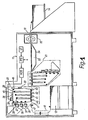
- Figure 1 depicts a printing system, which can be operated in a refurbishment mode according to an embodiment of the invention.
- Figure 2 depicts a printing system, which can be operated in a refurbishment mode according to an embodiment of the invention.
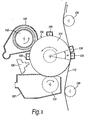
- Figure 3 depicts an image-forming station according to an embodiment of the invention.
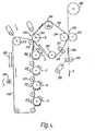
- Figure 4 depicts a printing system, which can be operated in a refurbishment mode according to an embodiment of the invention.
- the present invention is directed to a system and method for refurbishing an outer surface of endless members of an image reproduction system.
- image reproduction systems include digital printing or copying systems which carry toner images when operating in a printing mode. This is enabled by the provision of a control arrangement which allows the image reproduction system to switch between the printing mode and a refurbishment mode.
- an operator provides a command to a computer or controller which controls the image reproduction apparatus.
- the computer may use one or more processors, microprocessors, or microcontrollers. Software, used in connection with the processor, then deactivates certain functions and activates other functions.
- the refurbishment system and method can be employed offline, i.e., outside the image reproduction system, or online.
- the online implementation within the image reproduction system is clearly advantageous compared to the offline refurbishment system as it reduces the chance of damaging the surface of the endless member during its removal from the reproduction system, handling, and replacement of the endless member into the system.
- such a configuration reduces the downtime of the image reproduction system, i.e., the time that the system is not operative in the printing mode.
- the image reproduction system comprises at least an endless member having an outer surface for carrying toner images in a printing mode; and a control arrangement for switching the image reproduction system between a printing mode and a refurbishing mode, wherein in the refurbishing mode the surface of the endless member is cleaned using a cleaning solution comprising at least one organic solvent, optionally, dependent on the selected cleaning solution, followed by a wiping step wherein the liquid present on the surface of the endless member is removed.
- the receptor material for carrying the printed images can be in web form or in sheet form. In the latter case, the receptor material is preferably transported on a conveyor. Typical receptor materials are paper, films, label stock, cardboard, etc.
- the marking particles used to develop the images with the image reproduction system in the printing mode are toner particles.
- the toner particles may constitute dry particulate matter.
- a wet liquid type developer may be used wherein the toner particles are dispersed in a solvent.
- the development technique for electrophotographic printing systems applied in the examples further described herein uses a two-component dry developer material of toner particles adhering tribo-electrically to larger carrier beads.
- the developer material contained in a developer unit, is placed in an appropriate magnetic field, the carrier beads with the toner thereon form a magnetic brush.
- the toner particles are oppositely charged, in the development zone the toner particles are attracted to the carrier beads and develop the latent image on the image-forming member.
- both the developed image and the residual image are primarily composed of toner particles.
- the present invention is in no way limited to the refurbishing of endless members of electrophotographic image reproduction systems carrying dry toner images in the printing mode. To the contrary, the present invention is equally applicable when using a liquid type developer and/or image reproduction systems employing other image forming processes including but not limited to magnetography, ionography, direct electrostatic printing (DEP) and elcography.
- Examples of endless members having an outer surface for carrying toner images in a printing mode are image-forming members such as drums or belts with a seamed or seamless photosensitive outer layer.
- the photosensitive outer layer can be an organic photoconductor (OPC), for use in electrophotographic image reproduction systems, or a magneto-sensitive outer layer for use in magnetographic image reproduction systems.
- OPC organic photoconductor
- Examples of other image-carrying members are seamed or seamless intermediate transfer or transfuse drums or belts.
- Such an intermediate transfer member may be composed of an electrically semi-insulating or insulating material with a low surface energy, or comprise at least a top coating of such a material. Examples of such a material are polyesters such as e.g.
- transfuse members are members having at least an outermost layer of a material selected from the group of polyorganosiloxanes, fluorosilicones, phenylsilicones and fluoro-elastomers.
- the cleaning member is a roller.
- drive means may also be provided for cycling the cleaning member at a predetermined speed either continuously or discontinuously by means of a stepping motor.
- the cleaning member is a roller with a solid core covered with a, preferably open-celled, foamy layer.
- the cell size is preferably smaller than lmm, more preferably even smaller than 300 ⁇ m.
- the foamy layer is preferably composed of a material selected from the group including polyether, crosslinked polyesters, polyurethanes, derivated cellulose, and melamine.
- this foamy layer is covered with an impurity-absorbing material.
- the thickness of the impurity-absorbing material is typically from 100 ⁇ m to 300 ⁇ m.
- This impurity-absorbing material is preferably a lint-free material. Typical examples thereof are cootan or polyestercellulose.
- This foamy outer layer, and optionally the impurity absorbing layer, are impregnated with a predetermined amount of the cleaning solution.
- the cleaning member is a roller having a permeable, e.g., perforated, hollow core with a cleaning solution held therein and a foamy outer layer.
- an intermediate layer impregnated with said cleaning solution may be positioned around said hollow core, example by being wound around the core, and is covered with the foamy outer layer which will contact the endless member.
- the intermediate layer is typically formed of paper or felt. This optional layer may allow for a better control of the application rate of the cleaning solution.
- the application rate can be determined by the composition and thickness of the cleaning solution impregnated intermediate layer, the size and the distribution of the perforations in the core, the thickness and porosity of the foamy layer, the contact pressure between the cleaning roller and the endless member, the propagation speed of both cleaning roller and endless member, the temperature, and the chemical and physical properties of the cleaning solution.
- solvents showing at least an OH-functionality and which also comprise, within the same molecule, another polar group such as a ketone group, an ether group or and ester group show high solubilising power to the accumulated toner-based contaminants, and limited interaction with OPC.
- solvents are alkyl lactates, alkoxyalcohols, ethyllactate, furfuryalcohol, and methoxypropanol.
- a workable window can be created where the accumulated toner-based contaminants can be removed and at the same time no appreciable defects are induced in the OPC.
- the resident time of the cleaning solution can be carefully controlled by providing a wiping member in the system according to the present invention.
- the wiping member is positioned downstream of the cleaning member for contacting the outer surface of the image delivering member to thereby remove the liquid therefrom.
- the resident time of the cleaning solution on the outer surface of the image delivering member is determined by both the speed at which the image delivering member is cycled as well as the distance between contact zone of the cleaning member and the contact zone of the wiping member, and can be carefully controlled dependent on the properties of the cleaning solution.
- the wiping member may be of arbitrary shape, provided a continuous and uniform contact can be established with the outer surface of the image delivering member at least in the transverse direction.
- the wiping member is retractable and/or removable.
- This wiping member may be a roller or a web, endless or not, preferably having an outer layer composed of a lint-free material.
- Drive means may be provided to drive the wiping member at a predetermined speed.
- the -O- ⁇ group present in the low or non-solubility solvent molecules is e.g. ⁇ OH based such as in alcohols, even water, and e.g. ether groups,.... It has been observed also that one of the major advantages of cleaning solutions comprising such high/low solubility solvent mixtures is that the evaporation rate is high, particularly compared to cleaning solutions comprising at least one organic solvent showing at least an OH-functionality and which also comprises, within the same molecule, another polar group such as a ketone group, an ether group or an ester group.
- Cleaning solutions comprising such high/low solubility solvent mixtures can be further optimized with respect to their evaporation behavior. It has been found experimentally advantageous to combine solvents characterized by the fact that the high solubility solvent is more volatile than the low or non-solubility solvent. In this case the system is self-protective as in case a change in the solvent composition would occur, the relative amount of low or non-solubility solvent in the solution will increase and thus avoid a situation where at the end a high solubility solvent mixture remains and attacks the OPC.
- the ratio between the amount of high solubility solvent(s) and low or non-solubility solvent(s) in said solvent mixture is preferably between 0.3 and 3, more preferably between 0.6 and 1.5.
- the absolute value of the evaporation rate is preferably larger than 1, especially when using a single cleaning and wiping member. (The evaporation rate is defined relative to the evaporation rate of butylacetate.) Examples of such high/low solubility solvent mixtures are acetone/ methanol 50/50, MEK / ethanol: 40/60, ethylacetate / isopropanol: 50/50.
- a cleaning solution comprising such a mixture of solvents enables the use of a single cleaning member for both the solvent application and the removal of the solubilised accumulated toner-based contaminants.
- an air blower or a heating device may be provided downstream of said cleaning member to stimulate the evaporation of the cleaning solution from the outer surface of the image delivering member.
- viscosity increasing substances examples thereof are inter alia colloidal silica, alumina, both hyrophobized or not, and other fine materials. These materials also improve the adsorbing capability with respect to the toner-based contaminants. Also, a release agent may be incorporated as well as additives for rejuvenating the surface layer of the image delivering member.
- FIG. 1 a schematic representation of an electrophotographic duplex color printer is depicted.
- the printer comprises a light-tight housing 11, which has at its inside a stack 12 of sheets to be printed. At its output the printer has a platform 14 onto which the printed sheets are received.
- a sheet to be printed is removed from stack 12 and is fed through an alignment station 16. As the sheet leaves the alignment station, it follows a straight horizontal path 17 up to output section 18 of the printer. The speed of the sheet, upon entering said path, is determined by driven pressure roller pair 47. A number of processing stations are located along the path 17.
- a first image-forming unit 20 indicated in a dash-and-dot line is provided for applying a multi-color image to the obverse side of the sheet and is followed by a second station 21 for applying a multi-color image to the reverse sheet side.
- a buffer station 23 then follows, with an endless transport belt 24 for transporting the sheet to a fuser station 25.
- the photoconductive belt 26 is guided over a plurality of rollers 27 to follow a path in the direction of arrow 22 to advance successive portions of the photoconductive surface sequentially through the various processing stations disposed along the path of movement thereof.
- the photoconductive belt may comprise a base layer of polyethylene terephthalate of 100 ⁇ m thickness covered with a thin layer of aluminum as a back electrode (less than 0.5 ⁇ m thickness).
- the organic photoconductor (OPC) layer is on top of the aluminum layer and is from 15 ⁇ m in thickness.
- the belt is arranged such that the photoconductive layer is positioned on the outside of the belt loop.
- a portion of the photoconductive belt 26 passes through the charging station 28.
- a charge-generating device electrostatically charges the belt to a relatively high, substantially uniform potential, i.e., the dark potential.
- the belt passes to an exposure station 29.
- the exposure station 29 exposes the photoconductive belt to successively record four latent color separation images by image-wise discharging the belt.
- the belt advances these images to the development unit.
- This unit includes four individual developer stations 35, 36, 37 and 38 with, for example, cyan, yellow, magenta and black developer. During development of each electrostatic latent image only one developer station is in the operative position (developer station 35 in Figure 1).
- the developer used is two-component developer consisting of non-permanently magnetized magnetic carrier beads having toner particles adhering triboelectrically thereto.
- a magnetic brush of developer particles is formed in the operative developer station adjacent the photoconductive member.
- the negatively charged toner particles are attracted by an electrical field from the magnetic brush to thereby develop the corresponding latent image on the photoconductive belt.
- Each latent image is developed subsequently using the developer station of the corresponding color to thereby form four spaced-apart subsequently developed images on the photoconductive belt.
- the toner images are moved to toner image transfer stations 40, 41, 42 and 43 where they are transferred on a sheet of receptor material.
- the sheet follows the rectilinear path 17 into contact with the photoconductive belt 26.
- the sheet is advanced in synchronism with the movement of the belt such that at each transfer station an image is transferred to the paper in perfect register one onto the other to thereby form a registered multi-color image on the sheet.
- the belt which acts both as an image-delivering and an image-forming member, is directed towards a cleaning unit 45, which is positioned downstream from the transfer stations. In the cleaning unit, a rotating fibrous-like brush contacts the photoconductive belt 26 to remove residual toner particles remaining after the transfer operation.
- the cleaning brush rotates preferably in a direction opposite to the propagation direction of the image-delivering member.
- a collecting roller contacts the cleaning brush and rotates in a direction, preferably opposite to the rotation direction of the cleaning brush.
- the collecting roller may be a freely rotating roller or may be driven.
- the cleaning brush and the collecting roller may be independently driven and their rotation speed may be independently controlled.
- the collecting roller is incompressible and electrically conductive. Bias means are provided to apply a voltage to the collecting roller in order to create an electrical field which is attractive for the toner gathered on the cleaning brush.
- the cleaning unit may further comprise an auger positioned below the collecting roller. The auger removes the waste toner which is scraped off the collecting roller by a cleaning blade. Airflow may be provided to assist in the removal of the waste developer. Alternatively, instead of an auger, only airflow may be provided to remove the waste. Thereafter, a lamp 46 illuminates the belt to remove any residual charge remaining thereon prior to the start of a next cycle.
- the cleaning unit 45 effectively cleans the outer surface of the photoconductive belt, it is believed that over time by the mechanical action of the cleaning brush on the surface filming may occur. Moreover, as micro-cracks, scratches and other defects, in the printing mode, compressed toner particles and other extraneous matter may accumulate on these defects. The matter accumulated on the surface of the image delivering member can usually not be removed by the cleaning brush or blade. To the contrary, during subsequent cycles more and more toner tends to adhere to this already accumulated matter leading to clearly visible marks in the final image. Removing this accumulated matter and/ or filming clearly enhances reliability and lifetime of the OPC.
- a control arrangement is provided to switch the printer between the printing mode and the refurbishing mode.
- a drive motor (not shown) is provided to drive the photoconductive belt independently at a controlled speed typically in the range from 1 to 20 cm/s, while all other components are disabled.
- a cleaning roller having a 1.5-cm thick outer layer of melamine is presoaked in a cleaning solution comprising a 50/50 mixture of acetone and methanol. This presoaked cleaning roller is placed in the system. For instance, the cleaning unit may be temporarily replaced by the cleaning roller.
- pressure contact is established between the driven cleaning roller and a backing roller while the photoconductive belt is guided in between.
- the cleaning roller is driven by means of a stepping motor.
- the length (the longitudinal dimension) of the contact zone is typically about 1 cm.
- a thin layer of the cleaning solution is applied on the outer surface of the photoconductive belt. This may be done at a controlled temperature, usually a fixed temperature in the range from 15 to 35 Centigrade degrees or about room temperature. No other means are engaged against the outer surface of the photoconductive belt.
- the development stations 35, 36, 37, 38 may be temporarily removed from the system or sealed from the environment to prevent any undesirable interaction between the toner and the (volatile components) of the cleaning solution leading to, for example, toner clustering.
- the vapors are normally removed by the airflow present in the cleaning unit. Extra vapor evacuating means may be provided.
- the cleaning roller By cycling the photoconductive belt while in rolling contact with the cleaning roller, the cleaning roller gradually releases its predetermined amount of cleaning solution.
- the cleaning solution which is already applied on the outer surface of the photoconductive belt, gradually evaporates after interaction with the contaminants present on the surface.
- the cleaning roller has released all of its cleaning solution, which is after at least one complete cycle of the photoconductive belt, the dried cleaning roller removes any remaining residual contamination from the belt surface.
- a photoconductive member usually comprises a conductive backing layer with thereon a photosensitive layer comprising a charge generating material and a charge transport material.
- a photosensitive layer comprising a charge generating material and a charge transport material.
- two photosensitive layers may be provided wherein the first layer is provided on the conductive support and comprises a charge generating material, while the second layer is formed on said first one and comprises a charge transport material.
- An outer protective layer may be provided on the photosensitive layer, e.g., to prevent contamination of the photosensitive layer or to improve release. While the solvent refurbishing method of the present invention is applicable regardless of the nature of the outermost layer, the abrasive refurbishment method may not be applicable when the outermost layer is a protective layer. The repeated abrasion removes a thin stratum of the outermost layer which may have an adverse effect on the life-time of the photoconductive member.
- each printing station comprises a cylindrical drum 124 having a photoconductive outer surface 126. The drum acts both as an image-delivering member and as an image-forming member.
- This latent image is developed on the drum by the developer station 132 by contacting the drum with a magnet brush of a two-component developer of non-permanently magnetized magnetic carrier beads having toner particles adhering triboelectrically thereto formed on the surface of a magnet roller 133. Negatively charged toner particles are attracted to the exposed (discharged) areas of the photoconductor.
- the toner image on the drum surface is transferred to the moving web 112 by a transfer corona device 134 which generates an attractive electrical field for the negatively charged toner particles.
- This transfer corona together with the guiding rollers 136 establishes also a strong adherent contact between the web and the drum over an angle of about 15 degrees which causes the latter to be rotated in synchronism with the movement of the web 112 and urges the toner particles into firm contact with the surface of the web 112.
- a web discharge corona 138 is provided to establish a controlled release of the web.
- the cleaning unit 142 is similar to the cleaning unit 45 ( Figure 1) as described above.
- the cleaning unit includes an adjustably mounted fibrous-like cleaning brush 143, the position of which can be adjusted towards or away from the drum surface to ensure optimum cleaning.
- the cleaning brush 143 is grounded or subject to a potential with respect to the drum so as to attract the residual developer particles away from the drum surface.
- the rest of cleaning unit 142 is similar to the cleaning unit 45 ( Figure 1) as described above.
- the rotatable cleaning brush 143 which is driven to rotate in a sense the same as to that of the drum 124 and at a peripheral speed of, for example twice the peripheral speed of the drum surface.
- the developer station 132 includes a magnetic roller with a brush formed thereon 133 which rotates in a sense opposite to that of the drum 124.
- the resultant torque applied to the drum by the rotating developing brush 133 and the counter-rotating cleaning brush 143 is adjusted to be close to zero, thereby ensuring that the only torque applied to the drum is derived from the adherent force between the drum and the web.
- the web passes successively the other print stations where image of other colors are formed and transferred in register to thereby form a registered multi-color image on the web.
- the image on the web is fixed by means of the image fixing station 116 and fed to a cutting station 120 and a stacker 152 if desired.
- a control arrangement is provided to switch the printer between the printing mode and a number of refurbishing modes, wherein in each refurbishment mode a particular photoconductive drum is refurbished.
- a drive motor (not shown) is provided to drive the selected photoconductive drum independently at a controlled speed while all other components, including the web of recording material, are disengaged and/or disabled.
- a cleaning roller having a 1.5 cm thick outer layer of melamine is presoaked in a cleaning solution comprising a 50/50 mixture of acetone and methanol and replaces the cleaning unit 142. Contact is established between the cleaning roller and the selected photoconductive drum to initiate the refurbishment similarly as disclosed in the previous example.
- FIG. 4 a schematic representation of an electrophotographic color printer is depicted incorporating cleaning units according to the present invention.
- the printer comprises a primary transfer belt 212 formed of polyethylene terephthalate (PET) having a thickness of 100 ⁇ m and having spaced along one run thereof a plurality of toner image-forming stations A, B, C, D. Each of these stations is similar as described in Figure 3 and example 2.
- the charge generating devices 219, 221, 223, 225 are provided to subsequently electrostatically transfer a toner image of a particular color from each image-forming station to the PET belt 212 while the belt is advanced over a number of guide rollers 217 along the stations to thereby form a registered multi-color toner image.
- the primary transfer belt 212 acts as an image-delivering member.
- the multi-color toner image is transferred to an intermediate transfer belt 250.
- the intermediate transfer nip 216 is formed between the guide roller 213 and an opposing guide roller 252 pressed towards each other to cause tangential contact between said primary transfer belt 212 and a heated intermediate transfer belt 250.
- the guide roller 213 comprises an electrically conductive core carrying a semi-insulating covering.
- a supply of electrical potential is provided for electrically biasing at least the first guide roller 213 to create an electrical field at the intermediate transfer nip 216 to assist in transferring an image 214 from the primary belt 212 to the intermediate transfer belt 250.
- the primary transfer belt 212 passes thereafter through a cooling station 268, where the belt is forcibly cooled by directing cooled air onto the primary transfer belt 212.
- a cooling liquid such as water may be directed through roller 215 to cool the primary transfer belt.
- the primary transfer belt 212 is thereby cooled to a temperature of about 35 C. This cooling assists in establishing the required temperature gradient at the intermediate transfer nip 216.
- the residual toner image on the primary transfer belt 212 is removed by the cleaning unit 246 before the deposition of further developed toner images thereon.
- the intermediate transfer belt, i.e., the transfuse belt, 250 with the transferred multi-color image is advanced over a heated roller 266 to a final transfer station 226.
- the final transfer station 226 comprises a nip formed between a guide roller 254 of the intermediate transfer belt 250 and a counter roller 270, through which the intermediate transfer belt 250 and a substrate in the form of a paper web 258 pass in intimate contact with each other.
- Drive rollers 262 driven by a motor 230, drive the web 258 in the direction of the arrow X from a supply roll 260 continuously through the final transfer station 226 where it is pressed against the intermediate transfer belt 250 by the counter roller 270.
- the multi-color image is transferred from the intermediate transfer belt to the web of receptor material.
- the intermediate transfer belt 250 Downstream of the final transfer station 226, the intermediate transfer belt 250 passes through a cleaning station comprising a tacky cleaning roller 229 opposed to a counter roller 227, and thereafter over a steering and tensioning roller 232, before returning to the intermediate transfer nip 216.
- a control arrangement is provided to switch the printer between the printing mode and a number of refurbishing modes, wherein in each refurbishment mode a particular image delivering member is refurbished, e.g. one of the photoconductive drums, or the primary transfer member, or the intermediate transfer.
- a particular image delivering member is refurbished, e.g. one of the photoconductive drums, or the primary transfer member, or the intermediate transfer.
- this belt is separately driven at a controlled speed while all other components, including the primary transfer member and the web of recording material, are disengaged and/or disabled.
- a cleaning roller having a 1.5 cm thick outer layer of melamine is presoaked in a cleaning solution comprising a 50/50 mixture of acetone and methanol and replaces the tacky cleaning roller 229.
- a rolling contact is established between the cleaning roller and the intermediate transfer belt to initiate the refurbishment.
Landscapes
- Physics & Mathematics (AREA)
- General Physics & Mathematics (AREA)
- Cleaning In Electrography (AREA)
Applications Claiming Priority (2)
| Application Number | Priority Date | Filing Date | Title |
|---|---|---|---|
| US31468101P | 2001-08-24 | 2001-08-24 | |
| US314681 | 2001-08-24 |
Publications (1)
| Publication Number | Publication Date |
|---|---|
| EP1278106A2 true EP1278106A2 (de) | 2003-01-22 |
Family
ID=23220980
Family Applications (1)
| Application Number | Title | Priority Date | Filing Date |
|---|---|---|---|
| EP20020078521 Withdrawn EP1278106A2 (de) | 2001-08-24 | 2002-08-26 | Wiederherstellung von Bildträgerelementen eines Bildwiedergabesystem |
Country Status (1)
| Country | Link |
|---|---|
| EP (1) | EP1278106A2 (de) |
-
2002
- 2002-08-26 EP EP20020078521 patent/EP1278106A2/de not_active Withdrawn
Similar Documents
| Publication | Publication Date | Title |
|---|---|---|
| JP4009513B2 (ja) | 定着装置及び画像形成装置 | |
| US20090252510A1 (en) | Image forming apparatus and process cartridge | |
| US6539197B2 (en) | Printer cleaning device | |
| JP3136381B2 (ja) | 現像手段を有する画像形成装置 | |
| JP7463193B2 (ja) | 画像形成装置 | |
| JPH11272096A (ja) | 湿式電子写真方式プリンタの転写ロ―ラクリ―ニング装置 | |
| US5142327A (en) | Electrophotographic copying process using two image areas | |
| US5598255A (en) | Electrostatographic printer for forming a toner image onto a receptor web adapted to reduce smudging | |
| US6459865B2 (en) | Liquid-developing electro-photographic printer photosensitive body cleaning method | |
| JP5094211B2 (ja) | 画像形成装置 | |
| JPH05333725A (ja) | 画像形成装置 | |
| JP4387833B2 (ja) | 画像形成装置 | |
| CN100565376C (zh) | 图像形成装置 | |
| JP2003091146A (ja) | 画像形成装置 | |
| US7627269B2 (en) | Image forming apparatus with charging member cleaning capabilities | |
| JP2004132993A (ja) | 像再現システムの像担持部材の刷新 | |
| JP3160104B2 (ja) | 画像形成装置 | |
| US20120148284A1 (en) | Cleaning rotatable member in electrophotographic printer | |
| JP3451451B2 (ja) | カラー画像形成装置およびカラー画像形成方法 | |
| JP2004020700A (ja) | 画像形成装置 | |
| JP3658583B2 (ja) | カラー画像形成装置およびカラー画像形成方法 | |
| JP2003186364A (ja) | 画像形成装置 | |
| JP2003122184A (ja) | 画像形成装置 | |
| EP0671668B1 (de) | Elektrostatographischer Drucker zur Erzeugung eines Tonerbildes auf einem bandförmigen Empfangselement | |
| JP2003098842A (ja) | 画像形成装置 |
Legal Events
| Date | Code | Title | Description |
|---|---|---|---|
| PUAI | Public reference made under article 153(3) epc to a published international application that has entered the european phase |
Free format text: ORIGINAL CODE: 0009012 |
|
| STAA | Information on the status of an ep patent application or granted ep patent |
Free format text: STATUS: THE APPLICATION HAS BEEN WITHDRAWN |
|
| AK | Designated contracting states |
Kind code of ref document: A2 Designated state(s): AT BE BG CH CY CZ DE DK EE ES FI FR GB GR IE IT LI LU MC NL PT SE SK TR |
|
| AX | Request for extension of the european patent |
Free format text: AL;LT;LV;MK;RO;SI |
|
| 18W | Application withdrawn |
Effective date: 20021212 |