EP1278314B1 - Module de surveillance pour des signaux en salves optiques - Google Patents
Module de surveillance pour des signaux en salves optiques Download PDFInfo
- Publication number
- EP1278314B1 EP1278314B1 EP01440225A EP01440225A EP1278314B1 EP 1278314 B1 EP1278314 B1 EP 1278314B1 EP 01440225 A EP01440225 A EP 01440225A EP 01440225 A EP01440225 A EP 01440225A EP 1278314 B1 EP1278314 B1 EP 1278314B1
- Authority
- EP
- European Patent Office
- Prior art keywords
- burst
- signals
- monitoring unit
- detector
- comparator
- Prior art date
- Legal status (The legal status is an assumption and is not a legal conclusion. Google has not performed a legal analysis and makes no representation as to the accuracy of the status listed.)
- Expired - Lifetime
Links
- 230000003287 optical effect Effects 0.000 title claims description 29
- 238000012544 monitoring process Methods 0.000 title claims description 21
- 238000005259 measurement Methods 0.000 claims description 25
- 238000012545 processing Methods 0.000 claims description 7
- 238000011084 recovery Methods 0.000 claims description 7
- 238000000605 extraction Methods 0.000 claims description 6
- 230000001960 triggered effect Effects 0.000 claims 1
- 230000001360 synchronised effect Effects 0.000 description 7
- 238000005070 sampling Methods 0.000 description 6
- 238000001514 detection method Methods 0.000 description 5
- 230000005540 biological transmission Effects 0.000 description 3
- 238000000034 method Methods 0.000 description 3
- 238000004891 communication Methods 0.000 description 2
- 238000012937 correction Methods 0.000 description 2
- 238000010586 diagram Methods 0.000 description 2
- RGNPBRKPHBKNKX-UHFFFAOYSA-N hexaflumuron Chemical compound C1=C(Cl)C(OC(F)(F)C(F)F)=C(Cl)C=C1NC(=O)NC(=O)C1=C(F)C=CC=C1F RGNPBRKPHBKNKX-UHFFFAOYSA-N 0.000 description 2
- 238000012360 testing method Methods 0.000 description 2
- 230000015556 catabolic process Effects 0.000 description 1
- 238000011157 data evaluation Methods 0.000 description 1
- 238000006731 degradation reaction Methods 0.000 description 1
- 238000013213 extrapolation Methods 0.000 description 1
- 230000001788 irregular Effects 0.000 description 1
- 239000013307 optical fiber Substances 0.000 description 1
- 238000007619 statistical method Methods 0.000 description 1
- 238000012546 transfer Methods 0.000 description 1
Images
Classifications
-
- H—ELECTRICITY
- H04—ELECTRIC COMMUNICATION TECHNIQUE
- H04L—TRANSMISSION OF DIGITAL INFORMATION, e.g. TELEGRAPHIC COMMUNICATION
- H04L1/00—Arrangements for detecting or preventing errors in the information received
- H04L1/20—Arrangements for detecting or preventing errors in the information received using signal quality detector
-
- H—ELECTRICITY
- H04—ELECTRIC COMMUNICATION TECHNIQUE
- H04B—TRANSMISSION
- H04B10/00—Transmission systems employing electromagnetic waves other than radio-waves, e.g. infrared, visible or ultraviolet light, or employing corpuscular radiation, e.g. quantum communication
- H04B10/07—Arrangements for monitoring or testing transmission systems; Arrangements for fault measurement of transmission systems
- H04B10/075—Arrangements for monitoring or testing transmission systems; Arrangements for fault measurement of transmission systems using an in-service signal
- H04B10/079—Arrangements for monitoring or testing transmission systems; Arrangements for fault measurement of transmission systems using an in-service signal using measurements of the data signal
- H04B10/0795—Performance monitoring; Measurement of transmission parameters
- H04B10/07953—Monitoring or measuring OSNR, BER or Q
Definitions
- the invention relates to a monitoring unit, in particular for optical burst signals.
- an optical synchronous network such as a DWDM-SDH / SONET network
- DWDM Dense Wavelength Division Multiplex
- SDH Synchronous Digital Hierarchy
- SONET Synchronous Optical Network.
- Q-factor measurement is performed, which directly reflects the quality of the optical signal; Q stands for the Gaussian error integral. Q is obtained from the observation of the analog signal on the electrical level with its amplitude and phase characteristics. The method relies on targeted mis-sampling to simulate poor signal-to-noise ratio and increased bit error rate.
- Statistical methods can then be used to determine the Q factor, which corresponds to the conditions for optimal sampling.
- the principle of the Q-factor measuring device is based on a random sampling of the eye pattern.
- a comparator operates as a center sampler with fixed amplitude threshold and fixed phase, while a different comparator as a measuring scanner can vary these two parameters.
- Results of the two comparators are compared by an exclusive OR circuit and differences are counted as bit errors.
- the method is limited to synchronous, time-continuous signals with a stable, previously known sampling clock phase.
- WO 01/20452 A1 a protocol and bitratenunabhaengiges test system is known. It is used to detect bit errors in a digital communication channel, regardless of format or transmission rate.
- the test system includes two threshold detectors for determining whether the received signal in amplitude is between a minimum and a maximum value. Furthermore, a phase control is provided. By scanning, an eye measurement is performed.
- EP 0 999 670 A2 discloses a method for measuring the signal quality of a digital communication transmission system.
- a scanner with adjustable DC threshold, a detection device for determining the bit rate and a clock generator synchronized to the input signal are used for this purpose.
- the monitoring unit which may also be referred to as a measuring circuit, has to monitor optical bursts of fixed and / or variable length.
- the individual bursts are separated with so-called guard bands. From burst to burst, signal level fluctuations in the range of a few dB can occur.
- the clock frequency and phase angle can vary from burst to burst. Each burst has a short, pre-defined preamp for clock and amplitude recovery.
- the circuit according to the invention allows a scaling of the burst signal amplitude to be measured.
- the circuit also allows very fast burst clock recovery, which allows adjustment of the measurement to the current burst.
- the circuit also allows start-of-burst detection, which roughly makes the start time of a current burst based on the detection of the guard band. In a downstream burst synchronization logic, a fine determination of the start of the payload of the burst is performed.
- a basic idea of the invention is to synchronize each received burst and to determine for each burst a variable and a fixed amplitude threshold as well as a variable and a fixed phase position value.
- each burst included in the Q-factor measurement alternatively only every second burst can be synchronized and the corresponding values determined.
- the number the bursts flowing into the measurement can be selected at equidistant intervals, for example every, every second, every third, or, for example, at irregular intervals, for example selected by a random number generator.
- the invention is not limited to the monitoring of optical bursts, but may equally well be used for the monitoring of electrical bursts.
- the resulting error signal from the comparisons of the amplitude threshold values and the phase position values is passed on by means of a gate or not.
- the gate is controlled by the synchronization logic such that only the payload information of the burst data stream is used for the pseudo error measurement.
- Software-based processing extrapolates to the current bit error rate. Thus, early signal degradation can be detected.
- the header and control information of each burst is at least partially monitored and processed.
- the header and control information is used to distinguish between special burst flows, special named burst flows, and special switched paths, so-called label switched paths.
- the latter contain special header information, the labels.
- the inclusion of header and / or control information allows the measurement of specific, selected burst data streams, e.g. Flows, Connections, Label Switched Paths, with the ability to track such burst streams throughout the network.
- IP-based optical networks and optical terabit routing nodes are of particular interest to the telecom and data industries.
- the present invention provides performance monitoring that can be used at any point in the network or node, especially in an optically transparent domain called Optical Transparency Domain to monitor burst signals without special knowledge of the transport protocol used.
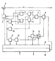
- the figure shows a monitoring unit according to the invention for optical burst signals.
- Optical networks are increasingly based on asynchronous, packet-oriented networks, e.g. ATM or Internet.
- burst-to-burst variations in signal level, clock frequency, and phase may occur.
- the monitoring unit takes these variations into account in the Q-factor measurement, which can be called a signal quality measurement, and performs a separate measurement for each burst.
- Each burst is synchronized and four measurement parameters are determined for each burst.
- the measurement parameters include a variable amplitude threshold, a fixed amplitude threshold, a variable phase position value, and a fixed phase position value.
- the eye diagram is evaluated at varying amplitude thresholds and sampling clock phases. This performs a pseudo-error measurement.
- the Q-factor and the current bit error rate are extrapolated and estimated from the measured values.
- the actual bit error measurement of a data signal is then determined at the end of a transmission path through the network in a receiver taking into account decoding, e.g. Viterbi decoder, error correction, e.g. Forward Error Correction, etc., where such a receiver is not part of the monitoring unit described here.
- the monitoring unit includes a detector for a Q-factor measurement as a function of at least one variable and at least one fixed amplitude threshold value and at least one variable and at least one fixed phase position value, which includes a burst amplitude detector 9 for generating a fixed amplitude threshold for each burst, a burst clock recovery 10 for generating a fixed phase position value for each burst, a burst detector 11 for detecting the start of a burst, and a control logic 15 for generating a variable amplitude Threshold and a variable phase position value for each burst.
- a detector for a Q-factor measurement as a function of at least one variable and at least one fixed amplitude threshold value and at least one variable and at least one fixed phase position value which includes a burst amplitude detector 9 for generating a fixed amplitude threshold for each burst, a burst clock recovery 10 for generating a fixed phase position value for each burst, a burst detector 11 for detecting
- the monitoring unit is connected via an asymmetrical optical coupler 1 to an optical line.
- the optical coupler 1 for example, decouples 10% of the signal level of the received signals and forwards them to an optical / electrical converter 2; the remaining 90% are e.g. forwarded to an optical receiver for data evaluation.
- the received optical burst signals are converted into electrical signals and then forwarded to five components.
- the forwarding takes place to a first comparator 3, a second comparator 5, the burst amplitude detector 9, the burst clock recovery 10 and the burst detector 11.
- the amplitudes of the electrical signal are compared with variable amplitude thresholds. For each burst, a new, variable amplitude threshold is determined.
- the amplitudes of the electrical signal are compared with fixed amplitude thresholds. For each burst, a new, fixed amplitude threshold is determined. The determination takes place in the amplitude detector 9, which selects an average, for example in the form of a fixed threshold voltage.
- the comparator 3 is followed by a decision maker 4.
- the output signal supplied by the comparator 3 is sampled, in response to a variable phase. For each burst a new, variable phasing value is determined.
- a variable amplitude threshold value and a variable phase angle value flow into the output signal of the decoder per burst.
- the comparator 5 is followed by a decision maker 6.
- the output signal supplied by the comparator 5 is sampled, in response to a fixed phase.
- a new, fixed phasing value is determined.
- a fixed amplitude threshold value and a fixed phase position value flow into the output signal of the decoder per burst.
- the determination of the fixed phase position value takes place in the burst clock recovery 10, which selects a mean value of a fixed phase from the sampling clock.
- Gate 8 provides an error signal which is fed to a processing unit 16.
- the processing unit 16 is, for example, a suitably programmed microprocessor. It is fed with control data for calculating extrapolation and estimation. From the error signal and the control data, the processing unit 16 determines an estimate of the Q-factor output via an output and used to monitor and control the network, e.g. to adjust the signal power at the transmitting end or to reconfigure the network if the signal quality of the respective monitored path falls below certain limits.
- the burst detector 11 is used to detect the beginning of a burst. For this purpose, a start-of-burst detection is performed, which performs a rough determination of the start time of a current burst based on the detection of the guard band.
- This start-of-burst information is provided on the one hand to the control logic 15 and on the other hand one Downstream burst synchronization logic 12, which makes a fine determination of the start of the payload of the burst.
- This start-of-payload information is provided to the control logic 15.
- the control logic 15 generates from the start-of-burst and the start-of-payload information as well as other information received from the processing unit 16 and containing the eye diagram information, a variable amplitude threshold and a variable phase lag value every burst.
- the control logic 15 is embodied, for example, as a correspondingly programmed microprocessor.
- Control logic 15 and processing unit 16 can also be implemented jointly on a microprocessor, digital signal processor, FPGA or the like and have at least one data interface for the purpose of data exchange.
- the start-of-payload information is further supplied to an extraction unit 13 and a switch 14 and the control logic 15th
- the extraction unit 13 is used for extraction of the header and / or control information.
- the header information and / or the control information is used for the selective measurement of special bursts and is forwarded to the switch 14 and to the control logic 15th
- Switch 14 is driven by control logic 15 which selects which variant of the measurement to perform, a general Q-factor measurement for all bursts, or a selective Q-factor measurement for specific bursts.
- the start-of-payload information is forwarded as a control signal to the gate 8, for the second variant, the header information.
- the variable amplitude threshold values and the variable phase angle values are additionally determined as a function of the header information.
- Extraction unit 13 and switch 14 are optional. If no Q-factor measurement or estimation of special bursts is provided, then you can a direct connection of output burst synchronization logic 12 and control input gate 8 are replaced.
Landscapes
- Engineering & Computer Science (AREA)
- Computer Networks & Wireless Communication (AREA)
- Signal Processing (AREA)
- Physics & Mathematics (AREA)
- Electromagnetism (AREA)
- Quality & Reliability (AREA)
- Optical Communication System (AREA)
- Data Exchanges In Wide-Area Networks (AREA)
Claims (4)
- Module de surveillance pour des signaux en salves, contenant un détecteur pour une mesure du facteur Q en fonction au moins de deux valeurs de seuil d'amplitude variables et au moins de deux valeurs de seuil d'amplitude fixes et au moins de deux valeurs de relation de phase variables et au moins de deux valeurs de relation de phase fixes, le détecteur contenant un détecteur d'amplitude de salves (9) destiné à générer une valeur de seuil d'amplitude fixe pour chaque signal en salves à intégrer dans la mesure, une récupération des impulsions de salves (10) destinée à générer une valeur de relation de phase fixe pour chaque signal en salves à intégrer dans la mesure et un système logique de commande (15) destiné à générer valeur de seuil d'amplitude variable et une valeur de relation de phase variable pour chaque signal en salves à intégrer dans la mesure, caractérisé en ce que le détecteur contient un détecteur de salves (11) destiné à détecter le début respectif des signaux en salves, et en ce que le module de surveillance contient en outre : un premier comparateur (3) destiné à comparer les signaux en salves reçus aux valeurs de seuil d'amplitude variables générées associées, un second comparateur (5) destiné à comparer les signaux en salves reçus aux valeurs de seuil d'amplitude fixes générées associées, un premier décideur (4) connecté en aval au premier comparateur (3) destiné à transmettre les signaux de sortie du premier comparateur (3) en fonction des valeurs de relation de phase variables générées associées aux signaux en salves, un second décideur (6) connecté en aval au second comparateur (5) destiné à transmettre les signaux de sortie du second comparateur (5) en fonction des valeurs de relation de phase fixes générées associées aux signaux en salves, et une porte de OU exclusif (7) destinée à lier les signaux de sortie du premier et du second décideur (5, 6).
- Module de surveillance selon la revendication 1, caractérisé en ce que le module de surveillance contient un système logique de synchronisation de salves (12) connecté en aval au détecteur de salves (11) destiné à déterminer le début respectif de la charge utile des signaux en salves et une porte (8) connectée en aval à la porte de OU exclusif et commandée par le système logique de synchronisation de salves (12) destiné à transmettre les signaux d'erreur à une unité de traitement (16) qui sert à estimer un facteur Q.
- Module de surveillance selon la revendication 2, caractérisé en ce que le module de surveillance contient une unité d'extraction (13) connectée en aval au système logique de synchronisation de salves (12) destiné à extraire les informations d'en-tête et/ou les informations de commande pour mesurer les signaux spéciaux en salves et un commutateur (14) commandé par le système logique de commande (15) qui est commuté entre l'unité d'extraction (13), le système logique de synchronisation de salves (12) et la porte (8).
- Module de surveillance selon la revendication 1, caractérisé en ce que le module de surveillance sert à la surveillance des signaux optiques en salves et contient un convertisseur optique/électrique (2) destiné à générer des signaux d'entrée électriques pour le détecteur d'amplitude de salves (9), la récupération des impulsions de salves (10) et le détecteur de salves (11).
Priority Applications (3)
| Application Number | Priority Date | Filing Date | Title |
|---|---|---|---|
| DE50111853T DE50111853D1 (de) | 2001-07-17 | 2001-07-17 | Überwachungseinheit für optische Burst-Signale |
| EP01440225A EP1278314B1 (fr) | 2001-07-17 | 2001-07-17 | Module de surveillance pour des signaux en salves optiques |
| US10/194,049 US7031616B2 (en) | 2001-07-17 | 2002-07-15 | Monitoring unit for optical burst mode signals |
Applications Claiming Priority (1)
| Application Number | Priority Date | Filing Date | Title |
|---|---|---|---|
| EP01440225A EP1278314B1 (fr) | 2001-07-17 | 2001-07-17 | Module de surveillance pour des signaux en salves optiques |
Publications (2)
| Publication Number | Publication Date |
|---|---|
| EP1278314A1 EP1278314A1 (fr) | 2003-01-22 |
| EP1278314B1 true EP1278314B1 (fr) | 2007-01-10 |
Family
ID=8183260
Family Applications (1)
| Application Number | Title | Priority Date | Filing Date |
|---|---|---|---|
| EP01440225A Expired - Lifetime EP1278314B1 (fr) | 2001-07-17 | 2001-07-17 | Module de surveillance pour des signaux en salves optiques |
Country Status (3)
| Country | Link |
|---|---|
| US (1) | US7031616B2 (fr) |
| EP (1) | EP1278314B1 (fr) |
| DE (1) | DE50111853D1 (fr) |
Families Citing this family (60)
| Publication number | Priority date | Publication date | Assignee | Title |
|---|---|---|---|---|
| JP2003158493A (ja) * | 2001-11-21 | 2003-05-30 | Mitsubishi Electric Corp | 光遮断検出装置、光受信器、光送信器及び光遮断検出方法 |
| US7791290B2 (en) * | 2005-09-30 | 2010-09-07 | Virgin Islands Microsystems, Inc. | Ultra-small resonating charged particle beam modulator |
| US20070034518A1 (en) * | 2005-08-15 | 2007-02-15 | Virgin Islands Microsystems, Inc. | Method of patterning ultra-small structures |
| US7586097B2 (en) * | 2006-01-05 | 2009-09-08 | Virgin Islands Microsystems, Inc. | Switching micro-resonant structures using at least one director |
| US7626179B2 (en) * | 2005-09-30 | 2009-12-01 | Virgin Island Microsystems, Inc. | Electron beam induced resonance |
| US7573815B2 (en) * | 2005-03-04 | 2009-08-11 | Alcatel-Lucent Usa Inc. | Flow control and congestion management for random scheduling in time-domain wavelength interleaved networks |
| WO2007014243A2 (fr) * | 2005-07-25 | 2007-02-01 | Mrv Communications, Inc. | Detecteur de presence de signaux |
| US20070116465A1 (en) * | 2005-11-21 | 2007-05-24 | Tellabs Operations, Inc. | Systems and methods for dynamic alignment of data bursts conveyed over a passive optical net work |
| US7579609B2 (en) * | 2005-12-14 | 2009-08-25 | Virgin Islands Microsystems, Inc. | Coupling light of light emitting resonator to waveguide |
| US20070152781A1 (en) * | 2006-01-05 | 2007-07-05 | Virgin Islands Microsystems, Inc. | Switching micro-resonant structures by modulating a beam of charged particles |
| US7470920B2 (en) * | 2006-01-05 | 2008-12-30 | Virgin Islands Microsystems, Inc. | Resonant structure-based display |
| US7619373B2 (en) * | 2006-01-05 | 2009-11-17 | Virgin Islands Microsystems, Inc. | Selectable frequency light emitter |
| US7605835B2 (en) * | 2006-02-28 | 2009-10-20 | Virgin Islands Microsystems, Inc. | Electro-photographic devices incorporating ultra-small resonant structures |
| US20070200063A1 (en) * | 2006-02-28 | 2007-08-30 | Virgin Islands Microsystems, Inc. | Wafer-level testing of light-emitting resonant structures |
| US7443358B2 (en) * | 2006-02-28 | 2008-10-28 | Virgin Island Microsystems, Inc. | Integrated filter in antenna-based detector |
| US20070200071A1 (en) * | 2006-02-28 | 2007-08-30 | Virgin Islands Microsystems, Inc. | Coupling output from a micro resonator to a plasmon transmission line |
| US20070200646A1 (en) * | 2006-02-28 | 2007-08-30 | Virgin Island Microsystems, Inc. | Method for coupling out of a magnetic device |
| US7558490B2 (en) * | 2006-04-10 | 2009-07-07 | Virgin Islands Microsystems, Inc. | Resonant detector for optical signals |
| US7876793B2 (en) * | 2006-04-26 | 2011-01-25 | Virgin Islands Microsystems, Inc. | Micro free electron laser (FEL) |
| US20070252089A1 (en) * | 2006-04-26 | 2007-11-01 | Virgin Islands Microsystems, Inc. | Charged particle acceleration apparatus and method |
| US7492868B2 (en) * | 2006-04-26 | 2009-02-17 | Virgin Islands Microsystems, Inc. | Source of x-rays |
| US20070264023A1 (en) * | 2006-04-26 | 2007-11-15 | Virgin Islands Microsystems, Inc. | Free space interchip communications |
| US7728702B2 (en) * | 2006-05-05 | 2010-06-01 | Virgin Islands Microsystems, Inc. | Shielding of integrated circuit package with high-permeability magnetic material |
| US20070272931A1 (en) * | 2006-05-05 | 2007-11-29 | Virgin Islands Microsystems, Inc. | Methods, devices and systems producing illumination and effects |
| US7569836B2 (en) * | 2006-05-05 | 2009-08-04 | Virgin Islands Microsystems, Inc. | Transmission of data between microchips using a particle beam |
| US7728397B2 (en) * | 2006-05-05 | 2010-06-01 | Virgin Islands Microsystems, Inc. | Coupled nano-resonating energy emitting structures |
| US7732786B2 (en) * | 2006-05-05 | 2010-06-08 | Virgin Islands Microsystems, Inc. | Coupling energy in a plasmon wave to an electron beam |
| US7710040B2 (en) * | 2006-05-05 | 2010-05-04 | Virgin Islands Microsystems, Inc. | Single layer construction for ultra small devices |
| US7554083B2 (en) * | 2006-05-05 | 2009-06-30 | Virgin Islands Microsystems, Inc. | Integration of electromagnetic detector on integrated chip |
| US20070258675A1 (en) * | 2006-05-05 | 2007-11-08 | Virgin Islands Microsystems, Inc. | Multiplexed optical communication between chips on a multi-chip module |
| US7342441B2 (en) | 2006-05-05 | 2008-03-11 | Virgin Islands Microsystems, Inc. | Heterodyne receiver array using resonant structures |
| US7656094B2 (en) * | 2006-05-05 | 2010-02-02 | Virgin Islands Microsystems, Inc. | Electron accelerator for ultra-small resonant structures |
| US7583370B2 (en) * | 2006-05-05 | 2009-09-01 | Virgin Islands Microsystems, Inc. | Resonant structures and methods for encoding signals into surface plasmons |
| US7443577B2 (en) * | 2006-05-05 | 2008-10-28 | Virgin Islands Microsystems, Inc. | Reflecting filtering cover |
| US7718977B2 (en) * | 2006-05-05 | 2010-05-18 | Virgin Island Microsystems, Inc. | Stray charged particle removal device |
| US7746532B2 (en) * | 2006-05-05 | 2010-06-29 | Virgin Island Microsystems, Inc. | Electro-optical switching system and method |
| US7741934B2 (en) * | 2006-05-05 | 2010-06-22 | Virgin Islands Microsystems, Inc. | Coupling a signal through a window |
| US20070258492A1 (en) * | 2006-05-05 | 2007-11-08 | Virgin Islands Microsystems, Inc. | Light-emitting resonant structure driving raman laser |
| US7442940B2 (en) | 2006-05-05 | 2008-10-28 | Virgin Island Microsystems, Inc. | Focal plane array incorporating ultra-small resonant structures |
| US7359589B2 (en) * | 2006-05-05 | 2008-04-15 | Virgin Islands Microsystems, Inc. | Coupling electromagnetic wave through microcircuit |
| US7723698B2 (en) * | 2006-05-05 | 2010-05-25 | Virgin Islands Microsystems, Inc. | Top metal layer shield for ultra-small resonant structures |
| US7436177B2 (en) | 2006-05-05 | 2008-10-14 | Virgin Islands Microsystems, Inc. | SEM test apparatus |
| US7586167B2 (en) * | 2006-05-05 | 2009-09-08 | Virgin Islands Microsystems, Inc. | Detecting plasmons using a metallurgical junction |
| US8188431B2 (en) * | 2006-05-05 | 2012-05-29 | Jonathan Gorrell | Integration of vacuum microelectronic device with integrated circuit |
| US7476907B2 (en) * | 2006-05-05 | 2009-01-13 | Virgin Island Microsystems, Inc. | Plated multi-faceted reflector |
| US7557647B2 (en) * | 2006-05-05 | 2009-07-07 | Virgin Islands Microsystems, Inc. | Heterodyne receiver using resonant structures |
| US7986113B2 (en) * | 2006-05-05 | 2011-07-26 | Virgin Islands Microsystems, Inc. | Selectable frequency light emitter |
| US7573045B2 (en) * | 2006-05-15 | 2009-08-11 | Virgin Islands Microsystems, Inc. | Plasmon wave propagation devices and methods |
| US20070274365A1 (en) * | 2006-05-26 | 2007-11-29 | Virgin Islands Microsystems, Inc. | Periodically complex resonant structures |
| US7679067B2 (en) * | 2006-05-26 | 2010-03-16 | Virgin Island Microsystems, Inc. | Receiver array using shared electron beam |
| US7655934B2 (en) * | 2006-06-28 | 2010-02-02 | Virgin Island Microsystems, Inc. | Data on light bulb |
| US7450794B2 (en) * | 2006-09-19 | 2008-11-11 | Virgin Islands Microsystems, Inc. | Microcircuit using electromagnetic wave routing |
| US7560716B2 (en) * | 2006-09-22 | 2009-07-14 | Virgin Islands Microsystems, Inc. | Free electron oscillator |
| US8243869B2 (en) * | 2006-11-28 | 2012-08-14 | Broadlight Ltd. | Burst mode clock and data recovery circuit and method |
| US7659513B2 (en) * | 2006-12-20 | 2010-02-09 | Virgin Islands Microsystems, Inc. | Low terahertz source and detector |
| US7925156B2 (en) * | 2007-01-16 | 2011-04-12 | Broadlight, Ltd. | Apparatus and method for measuring the quality of burst signals and performing optical line diagnostics |
| US7990336B2 (en) * | 2007-06-19 | 2011-08-02 | Virgin Islands Microsystems, Inc. | Microwave coupled excitation of solid state resonant arrays |
| CN102088320B (zh) * | 2009-12-03 | 2013-10-30 | 建兴电子科技股份有限公司 | 超音波系统及其通讯方法 |
| US8693593B2 (en) * | 2010-12-30 | 2014-04-08 | Lsi Corporation | Methods and apparatus for automatic gain control using samples taken at desired sampling phase and target voltage level |
| CN103957066B (zh) * | 2014-05-21 | 2015-09-09 | 电子科技大学 | 一种基于非参数核函数的短时突发通信信号检测方法 |
Family Cites Families (6)
| Publication number | Priority date | Publication date | Assignee | Title |
|---|---|---|---|---|
| US5040194A (en) * | 1986-07-15 | 1991-08-13 | Hayes Microcomputer Products, Inc. | Method and apparatus for providing for automatic gain control of incoming signals in a modem |
| US5365516A (en) * | 1991-08-16 | 1994-11-15 | Pinpoint Communications, Inc. | Communication system and method for determining the location of a transponder unit |
| US5546325A (en) * | 1993-02-04 | 1996-08-13 | International Business Machines Corporation | Automated system, and corresponding method, for testing electro-optic modules |
| JPH07154378A (ja) * | 1993-12-01 | 1995-06-16 | Kokusai Denshin Denwa Co Ltd <Kdd> | 光伝送特性測定装置 |
| DE19850567C2 (de) * | 1998-11-02 | 2001-02-15 | Wandel & Goltermann Man Holdin | Verwendung einer Schaltungsanordnung und Vorrichtung zur Messung der Signalgüte eines digitalen Nachrichtenübertragungssystems |
| US6430715B1 (en) * | 1999-09-17 | 2002-08-06 | Digital Lightwave, Inc. | Protocol and bit rate independent test system |
-
2001
- 2001-07-17 EP EP01440225A patent/EP1278314B1/fr not_active Expired - Lifetime
- 2001-07-17 DE DE50111853T patent/DE50111853D1/de not_active Expired - Lifetime
-
2002
- 2002-07-15 US US10/194,049 patent/US7031616B2/en not_active Expired - Lifetime
Also Published As
| Publication number | Publication date |
|---|---|
| US20030016412A1 (en) | 2003-01-23 |
| DE50111853D1 (de) | 2007-02-22 |
| EP1278314A1 (fr) | 2003-01-22 |
| US7031616B2 (en) | 2006-04-18 |
Similar Documents
| Publication | Publication Date | Title |
|---|---|---|
| EP1278314B1 (fr) | Module de surveillance pour des signaux en salves optiques | |
| DE60128784T2 (de) | Verfahren und Vorrichtung zur effizienten und genauen Grobzeitsynchronisierung in Pulsdemodulatoren | |
| EP1155531B1 (fr) | Systeme et procede de mesure des durees de transfert et des taux de pertes dans des reseaux de telecommunication haut-debit | |
| DE10031943B4 (de) | Bitraten-unabhängiger optischer Empfänger und Verfahren dafür | |
| US20090109858A1 (en) | Communication Quality Determining Apparatus, Communication Quality Determining Method and Its Program | |
| DE60226190T2 (de) | Verfahren und Vorrichtung zur Messung und Bestimmung des optischen Signal-Rauschverhältnis in optischen Netzwerken | |
| DE102004014695A1 (de) | Takt- und Datenwiedergewinnungseinheit | |
| US9270568B2 (en) | Method and an apparatus for determining the presence of a rate limiting mechanism in a network | |
| JP4189000B2 (ja) | エンドポイントデータを使用したネットワークにおけるパケット損失率の測定 | |
| WO2002098035A1 (fr) | Module de verrouillage de trames agile a protocoles multiples | |
| DE69929881T2 (de) | Verfahren und gerät zum automatisierten zeitdomänenüberwachen in optischen netzen | |
| DE10219154A1 (de) | Verfahren zur Überwachung der Verfügbarkeit von Verbindungen in MPLS-Netzen | |
| US7751726B1 (en) | Automatic selection of the performance monitoring based on client type | |
| WO2003094442A1 (fr) | Procede pour surveiller la qualite de transmission de liaisons dans des reseaux mpls | |
| EP0999670B1 (fr) | Procédé et dispositif pour mesurer la qualité de signal d'un système de transmission d'informations numériques | |
| DE102004063567A1 (de) | Dienstunterbrechungszeitbestimmungsvorrichtung und -Verfahren | |
| DE2921089A1 (de) | Verfahren zum erzeugen eines pseudofehlersignals in einer fehlerrate- ueberwachungseinheit und schaltung zur ausfuehrung des verfahrens | |
| WO2008040378A1 (fr) | Indicateur de qualité de signal | |
| Ohta et al. | Divide and conquer technique for network fault management | |
| WO2004073244A1 (fr) | Procede et dispositif de surveillance de taux d'erreurs sur les bits | |
| EP1159807B1 (fr) | Procede et dispositif d'obtention automatique de signaux d'horloge pour l'echantillonnage de signaux de donnees a des debits de donnees differents a l'aide d'une boucle a phase asservie | |
| Chabchoub et al. | Deterministic versus probabilistic packet sampling in the Internet | |
| DE69525391T2 (de) | Signalerkennungseinrichtung und Taktrückgewinnungseinrichtung welche diese Signalerkennungseinrichtung verwendet | |
| DE102006045050B4 (de) | Verfahren und Vorrichtung zur Bestimmung der Latenzzeit eines digitalen Übertragungssystems, insbesondere eines digitalen optischen Übertragungssystems | |
| DE10010947A1 (de) | Takt- und Datenregenerator für unterschiedliche Datenraten |
Legal Events
| Date | Code | Title | Description |
|---|---|---|---|
| PUAI | Public reference made under article 153(3) epc to a published international application that has entered the european phase |
Free format text: ORIGINAL CODE: 0009012 |
|
| 17P | Request for examination filed |
Effective date: 20021001 |
|
| AK | Designated contracting states |
Kind code of ref document: A1 Designated state(s): AT BE CH CY DE DK ES FI FR GB GR IE IT LI LU MC NL PT SE TR |
|
| AX | Request for extension of the european patent |
Free format text: AL;LT;LV;MK;RO;SI |
|
| AKX | Designation fees paid |
Designated state(s): AT BE CH CY DE DK ES FI FR GB GR IE IT LI LU MC NL PT SE TR |
|
| 17Q | First examination report despatched |
Effective date: 20031103 |
|
| GRAP | Despatch of communication of intention to grant a patent |
Free format text: ORIGINAL CODE: EPIDOSNIGR1 |
|
| GRAS | Grant fee paid |
Free format text: ORIGINAL CODE: EPIDOSNIGR3 |
|
| GRAA | (expected) grant |
Free format text: ORIGINAL CODE: 0009210 |
|
| AK | Designated contracting states |
Kind code of ref document: B1 Designated state(s): AT BE CH CY DE DK ES FI FR GB GR IE IT LI LU MC NL PT SE TR |
|
| PG25 | Lapsed in a contracting state [announced via postgrant information from national office to epo] |
Ref country code: DK Free format text: LAPSE BECAUSE OF FAILURE TO SUBMIT A TRANSLATION OF THE DESCRIPTION OR TO PAY THE FEE WITHIN THE PRESCRIBED TIME-LIMIT Effective date: 20070110 Ref country code: NL Free format text: LAPSE BECAUSE OF FAILURE TO SUBMIT A TRANSLATION OF THE DESCRIPTION OR TO PAY THE FEE WITHIN THE PRESCRIBED TIME-LIMIT Effective date: 20070110 Ref country code: FI Free format text: LAPSE BECAUSE OF FAILURE TO SUBMIT A TRANSLATION OF THE DESCRIPTION OR TO PAY THE FEE WITHIN THE PRESCRIBED TIME-LIMIT Effective date: 20070110 Ref country code: IE Free format text: LAPSE BECAUSE OF FAILURE TO SUBMIT A TRANSLATION OF THE DESCRIPTION OR TO PAY THE FEE WITHIN THE PRESCRIBED TIME-LIMIT Effective date: 20070110 |
|
| REG | Reference to a national code |
Ref country code: GB Ref legal event code: FG4D Free format text: NOT ENGLISH |
|
| RIN1 | Information on inventor provided before grant (corrected) |
Inventor name: BIGALK, UWE Inventor name: EILENBERGER, GERT, DR. |
|
| REG | Reference to a national code |
Ref country code: IE Ref legal event code: FG4D Free format text: LANGUAGE OF EP DOCUMENT: GERMAN |
|
| REF | Corresponds to: |
Ref document number: 50111853 Country of ref document: DE Date of ref document: 20070222 Kind code of ref document: P |
|
| GBT | Gb: translation of ep patent filed (gb section 77(6)(a)/1977) |
Effective date: 20070207 |
|
| RAP2 | Party data changed (patent owner data changed or rights of a patent transferred) |
Owner name: ALCATEL LUCENT |
|
| PG25 | Lapsed in a contracting state [announced via postgrant information from national office to epo] |
Ref country code: SE Free format text: LAPSE BECAUSE OF FAILURE TO SUBMIT A TRANSLATION OF THE DESCRIPTION OR TO PAY THE FEE WITHIN THE PRESCRIBED TIME-LIMIT Effective date: 20070410 |
|
| PG25 | Lapsed in a contracting state [announced via postgrant information from national office to epo] |
Ref country code: ES Free format text: LAPSE BECAUSE OF FAILURE TO SUBMIT A TRANSLATION OF THE DESCRIPTION OR TO PAY THE FEE WITHIN THE PRESCRIBED TIME-LIMIT Effective date: 20070421 |
|
| NLT2 | Nl: modifications (of names), taken from the european patent patent bulletin |
Owner name: ALCATEL LUCENT Effective date: 20070404 |
|
| PG25 | Lapsed in a contracting state [announced via postgrant information from national office to epo] |
Ref country code: PT Free format text: LAPSE BECAUSE OF FAILURE TO SUBMIT A TRANSLATION OF THE DESCRIPTION OR TO PAY THE FEE WITHIN THE PRESCRIBED TIME-LIMIT Effective date: 20070611 |
|
| NLV1 | Nl: lapsed or annulled due to failure to fulfill the requirements of art. 29p and 29m of the patents act | ||
| ET | Fr: translation filed | ||
| REG | Reference to a national code |
Ref country code: IE Ref legal event code: FD4D |
|
| PLBE | No opposition filed within time limit |
Free format text: ORIGINAL CODE: 0009261 |
|
| STAA | Information on the status of an ep patent application or granted ep patent |
Free format text: STATUS: NO OPPOSITION FILED WITHIN TIME LIMIT |
|
| 26N | No opposition filed |
Effective date: 20071011 |
|
| BERE | Be: lapsed |
Owner name: ALCATEL Effective date: 20070731 |
|
| REG | Reference to a national code |
Ref country code: CH Ref legal event code: PL |
|
| PG25 | Lapsed in a contracting state [announced via postgrant information from national office to epo] |
Ref country code: MC Free format text: LAPSE BECAUSE OF NON-PAYMENT OF DUE FEES Effective date: 20070731 Ref country code: LI Free format text: LAPSE BECAUSE OF NON-PAYMENT OF DUE FEES Effective date: 20070731 Ref country code: CH Free format text: LAPSE BECAUSE OF NON-PAYMENT OF DUE FEES Effective date: 20070731 Ref country code: GR Free format text: LAPSE BECAUSE OF FAILURE TO SUBMIT A TRANSLATION OF THE DESCRIPTION OR TO PAY THE FEE WITHIN THE PRESCRIBED TIME-LIMIT Effective date: 20070411 |
|
| PG25 | Lapsed in a contracting state [announced via postgrant information from national office to epo] |
Ref country code: BE Free format text: LAPSE BECAUSE OF NON-PAYMENT OF DUE FEES Effective date: 20070731 |
|
| PG25 | Lapsed in a contracting state [announced via postgrant information from national office to epo] |
Ref country code: AT Free format text: LAPSE BECAUSE OF NON-PAYMENT OF DUE FEES Effective date: 20070717 |
|
| PG25 | Lapsed in a contracting state [announced via postgrant information from national office to epo] |
Ref country code: CY Free format text: LAPSE BECAUSE OF FAILURE TO SUBMIT A TRANSLATION OF THE DESCRIPTION OR TO PAY THE FEE WITHIN THE PRESCRIBED TIME-LIMIT Effective date: 20070110 |
|
| PG25 | Lapsed in a contracting state [announced via postgrant information from national office to epo] |
Ref country code: LU Free format text: LAPSE BECAUSE OF NON-PAYMENT OF DUE FEES Effective date: 20070717 |
|
| PG25 | Lapsed in a contracting state [announced via postgrant information from national office to epo] |
Ref country code: TR Free format text: LAPSE BECAUSE OF FAILURE TO SUBMIT A TRANSLATION OF THE DESCRIPTION OR TO PAY THE FEE WITHIN THE PRESCRIBED TIME-LIMIT Effective date: 20070110 |
|
| REG | Reference to a national code |
Ref country code: FR Ref legal event code: GC Effective date: 20140717 |
|
| REG | Reference to a national code |
Ref country code: FR Ref legal event code: RG Effective date: 20141016 |
|
| REG | Reference to a national code |
Ref country code: FR Ref legal event code: PLFP Year of fee payment: 15 |
|
| REG | Reference to a national code |
Ref country code: FR Ref legal event code: CA Effective date: 20150521 |
|
| REG | Reference to a national code |
Ref country code: FR Ref legal event code: CA Effective date: 20150521 |
|
| REG | Reference to a national code |
Ref country code: FR Ref legal event code: PLFP Year of fee payment: 16 |
|
| REG | Reference to a national code |
Ref country code: FR Ref legal event code: PLFP Year of fee payment: 17 |
|
| PGFP | Annual fee paid to national office [announced via postgrant information from national office to epo] |
Ref country code: IT Payment date: 20170728 Year of fee payment: 17 |
|
| REG | Reference to a national code |
Ref country code: FR Ref legal event code: PLFP Year of fee payment: 18 |
|
| REG | Reference to a national code |
Ref country code: DE Ref legal event code: R081 Ref document number: 50111853 Country of ref document: DE Owner name: PROVENANCE ASSET GROUP LLC, PITTSFORD, US Free format text: FORMER OWNER: ALCATEL LUCENT, PARIS, FR |
|
| PG25 | Lapsed in a contracting state [announced via postgrant information from national office to epo] |
Ref country code: IT Free format text: LAPSE BECAUSE OF NON-PAYMENT OF DUE FEES Effective date: 20180717 |
|
| REG | Reference to a national code |
Ref country code: GB Ref legal event code: 732E Free format text: REGISTERED BETWEEN 20190829 AND 20190904 |
|
| PGFP | Annual fee paid to national office [announced via postgrant information from national office to epo] |
Ref country code: FR Payment date: 20200629 Year of fee payment: 20 |
|
| PGFP | Annual fee paid to national office [announced via postgrant information from national office to epo] |
Ref country code: GB Payment date: 20200609 Year of fee payment: 20 |
|
| PGFP | Annual fee paid to national office [announced via postgrant information from national office to epo] |
Ref country code: DE Payment date: 20200601 Year of fee payment: 20 |
|
| REG | Reference to a national code |
Ref country code: DE Ref legal event code: R071 Ref document number: 50111853 Country of ref document: DE |
|
| REG | Reference to a national code |
Ref country code: GB Ref legal event code: PE20 Expiry date: 20210716 |
|
| PG25 | Lapsed in a contracting state [announced via postgrant information from national office to epo] |
Ref country code: GB Free format text: LAPSE BECAUSE OF EXPIRATION OF PROTECTION Effective date: 20210716 |